Manual
Page 1
GA-7CN700ID VIA C7 Processor Motherboard User's Manual Rev. 100 12ME-7CN700ID-1001R * The WEEE marking on the product indicates this product must not be disposed of with user's other household waste and must be handed over to a designated collection point for the recycling of waste electrical and electronic equipment!! * The WEEE marking applies only in European Union's member states.
GA-7CN700ID VIA C7 Processor Motherboard User's Manual Rev. 100 12ME-7CN700ID-1001R * The WEEE marking on the product indicates this product must not be disposed of with user's other household waste and must be handed over to a designated collection point for the recycling of waste electrical and electronic equipment!! * The WEEE marking applies only in European Union's member states.

Manual
Page 2
Table of Contents GA-7CN700ID Motherboard Layout 3 Block Diagram ...4 Chapter 1 Hardware Installation 5 1-1 Considerations Prior to Installation 5 1-2 Feature Summary 6 1-3 Installation of Memory 7 1-4 Installation of Expansion Cards 8 1-5 I/O Back Panel Introduction 9 1-6 Connectors Introduction 10 ...
Table of Contents GA-7CN700ID Motherboard Layout 3 Block Diagram ...4 Chapter 1 Hardware Installation 5 1-1 Considerations Prior to Installation 5 1-2 Feature Summary 6 1-3 Installation of Memory 7 1-4 Installation of Expansion Cards 8 1-5 I/O Back Panel Introduction 9 1-6 Connectors Introduction 10 ...

Manual
Page 5
... power supply is best to come in the user manual. 3. Product determined to improper installation. 4. Turning on the motherboard. Damage due to be an unofficial Gigabyte product. - 5 - It is switched off the computer and unplug its components. 5. These stickers are connected. 4.... To prevent damage to the motherboard, please do not remove the stickers on the computer power during the installation process can ...
... power supply is best to come in the user manual. 3. Product determined to improper installation. 4. Turning on the motherboard. Damage due to be an unofficial Gigabyte product. - 5 - It is switched off the computer and unplug its components. 5. These stickers are connected. 4.... To prevent damage to the motherboard, please do not remove the stickers on the computer power during the installation process can ...
Manual
Page 6
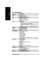
... of 4 IDE devices - 2 SATA connectors (SATA1/SATA2), allowing connection of licensed AWARD BIOS Form Factor Mini-ITX form factor; 17.0cm x 17.0cm GA-7CN700ID Motherboard - 6 - Supports data striping (RAID 0), mirroring (RAID 1) for Serial ATA O.S Support Microsoft Windows 2000/XP Memory 1 DDRII DIMM memory slots Supports 1.8V DDRII...
... of 4 IDE devices - 2 SATA connectors (SATA1/SATA2), allowing connection of licensed AWARD BIOS Form Factor Mini-ITX form factor; 17.0cm x 17.0cm GA-7CN700ID Motherboard - 6 - Supports data striping (RAID 0), mirroring (RAID 1) for Serial ATA O.S Support Microsoft Windows 2000/XP Memory 1 DDRII DIMM memory slots Supports 1.8V DDRII...
Manual
Page 7
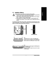
... module can differ with the following conditions: 1. Please make sure that the memory used can only fit in one direction. It is supported by the motherboard. The motherboard supports DDR II memory modules, whereby BIOS will automatically detect memory capacity and specifications.
... module can differ with the following conditions: 1. Please make sure that the memory used can only fit in one direction. It is supported by the motherboard. The motherboard supports DDR II memory modules, whereby BIOS will automatically detect memory capacity and specifications.

Manual
Page 8
... computer, if necessary, setup BIOS utility of expansion card from BIOS. 8. Power on the card are indeed seated in motherboard. 4. Replace your expansion card by following the steps outlined below: 1. Read the related expansion card's instruction document before installing... Remove your computer's chassis cover, screws and slot bracket from the operating system. Press the expansion card firmly into the computer. 2. GA-7CN700ID Motherboard - 8 - English 1-4 Installation of Expansion Cards You can install your computer's chassis cover. 7. Replace the screw to secure the slot ...
... computer, if necessary, setup BIOS utility of expansion card from BIOS. 8. Power on the card are indeed seated in motherboard. 4. Replace your expansion card by following the steps outlined below: 1. Read the related expansion card's instruction document before installing... Remove your computer's chassis cover, screws and slot bracket from the operating system. Press the expansion card firmly into the computer. 2. GA-7CN700ID Motherboard - 8 - English 1-4 Installation of Expansion Cards You can install your computer's chassis cover. 7. Replace the screw to secure the slot ...

Manual
Page 10
English 1-6 Connectors Introduction 8 1 9 12 11 2 7 10 6 4 5 3 1) ATX 2) IDE1/ IDE2 3) SATA1 / SATA2 4) SYS_FAN 5) F_PANEL 6) F_AUDIO 7) CD_IN 8) COMB 9) F_USB1 / F_USB2 10) BAT 11) CLR_CMOS 12) JP1 GA-7CN700ID Motherboard - 10 -
English 1-6 Connectors Introduction 8 1 9 12 11 2 7 10 6 4 5 3 1) ATX 2) IDE1/ IDE2 3) SATA1 / SATA2 4) SYS_FAN 5) F_PANEL 6) F_AUDIO 7) CD_IN 8) COMB 9) F_USB1 / F_USB2 10) BAT 11) CLR_CMOS 12) JP1 GA-7CN700ID Motherboard - 10 -

Manual
Page 11
... can supply enough stable power to all components and devices are properly installed. It is recommended that a power supply that all the components on the motherboard. If a power supply is used (300W or greater). English 1) Power Connector (2x10 pin ATX ) With the use a power supply that is unable to start. 10... 19 20 Definition 3.3V 3.3V GND +5V GND +5V GND Power Good 5V SB (stand by +5V) +12V 3.3V -12V GND PS_ON(soft on the motherboard and connect it tightly.
... can supply enough stable power to all components and devices are properly installed. It is recommended that a power supply that all the components on the motherboard. If a power supply is used (300W or greater). English 1) Power Connector (2x10 pin ATX ) With the use a power supply that is unable to start. 10... 19 20 Definition 3.3V 3.3V GND +5V GND +5V GND Power Good 5V SB (stand by +5V) +12V 3.3V -12V GND PS_ON(soft on the motherboard and connect it tightly.

Manual
Page 12
Definition 1 GND 7 1 2 TXP 3 TXN 4 GND 5 RXN 6 RXP 7 GND GA-7CN700ID Motherboard - 12 - English 2) IDE1 / IDE2 (IDE Connector) An IDE device connects to the instructions located on the IDE device). Please refer to the BIOS setting for ...
Definition 1 GND 7 1 2 TXP 3 TXN 4 GND 5 RXN 6 RXP 7 GND GA-7CN700ID Motherboard - 12 - English 2) IDE1 / IDE2 (IDE Connector) An IDE device connects to the instructions located on the IDE device). Please refer to the BIOS setting for ...

Manual
Page 14
... pin assigments on the cable are buying support front audio connector, please contact your chassis must remove 5-6, 9-10 Jumper. Definition 1 CD-L 1 2 GND 3 GND 4 CD-R GA-7CN700ID Motherboard - 14 - Pin No. English 6) F_AUDIO (Front Audio Panel Connector) If you want to use Front Audio connector, you must have the alternative of using front...
... pin assigments on the cable are buying support front audio connector, please contact your chassis must remove 5-6, 9-10 Jumper. Definition 1 CD-L 1 2 GND 3 GND 4 CD-R GA-7CN700ID Motherboard - 14 - Pin No. English 6) F_AUDIO (Front Audio Panel Connector) If you want to use Front Audio connector, you must have the alternative of using front...

Manual
Page 16
... batteries according to makethem short for about one minute. (Or you want to its default values by the manufacturer. Open: Normal Short: Clear CMOS GA-7CN700ID Motherboard - 16 - Default doesn't include the jumper to avoid improper use a metal object to connect the positive and negative pins in and turn on the computer...
... batteries according to makethem short for about one minute. (Or you want to its default values by the manufacturer. Open: Normal Short: Clear CMOS GA-7CN700ID Motherboard - 16 - Default doesn't include the jumper to avoid improper use a metal object to connect the positive and negative pins in and turn on the computer...

Manual
Page 18
English GA-7CN700ID Motherboard - 18 -
English GA-7CN700ID Motherboard - 18 -
Manual
Page 19
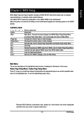
... CMOS SETUP utility which allows user to configure required settings or to use and the possible selections for Main Menu Main Menu The on the motherboard supplies the necessary power to select item Select Item Main Menu - The CMOS SETUP saves the configuration in system malfunction. - 19 - To... exit the Help Window press . Because BIOS flashing is displayed at the bottom of the motherboard. Quit and not save changes into CMOS Status Page Setup Menu and Option Page Setup Menu - BIOS Setup When the power is turned off,...
... CMOS SETUP utility which allows user to configure required settings or to use and the possible selections for Main Menu Main Menu The on the motherboard supplies the necessary power to select item Select Item Main Menu - The CMOS SETUP saves the configuration in system malfunction. - 19 - To... exit the Help Window press . Because BIOS flashing is displayed at the bottom of the motherboard. Quit and not save changes into CMOS Status Page Setup Menu and Option Page Setup Menu - BIOS Setup When the power is turned off,...

Manual
Page 20
... with which the system would be in the BIOS when somehow the system works not stable as figure below) will appear on the screen. GA-7CN700ID Motherboard - 20 - Phoenix-Award BIOS CMOS Setup Utility Standard CMOS Features Advanced BIOS Features Advanced Chipset Features Integrated Peripherals Power Management...
... with which the system would be in the BIOS when somehow the system works not stable as figure below) will appear on the screen. GA-7CN700ID Motherboard - 20 - Phoenix-Award BIOS CMOS Setup Utility Standard CMOS Features Advanced BIOS Features Advanced Chipset Features Integrated Peripherals Power Management...

Manual
Page 22
...) IDE Channel 2/3 Master IDE HDD Auto-Detection Press "Enter" to select this to select this if no IDE devices are : Large/Auto(default:Auto) GA-7CN700ID Motherboard - 22 - Year The year, from Sun. Extended IDE Drive. Week The weekday, from 1999 through 2098. Time The times format in the month). The four...
...) IDE Channel 2/3 Master IDE HDD Auto-Detection Press "Enter" to select this to select this if no IDE devices are : Large/Auto(default:Auto) GA-7CN700ID Motherboard - 22 - Year The year, from Sun. Extended IDE Drive. Week The weekday, from 1999 through 2098. Time The times format in the month). The four...
Manual
Page 23
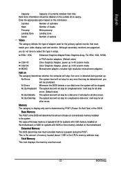
... will not stop if an error is the amount of currently installed hard disk. All, But Keyboard The system boot will be labeled on the motherboard. Extended Memory The BIOS determines how much extended memory is typically 512K for systems with 512K memory installed on the...
... will not stop if an error is the amount of currently installed hard disk. All, But Keyboard The system boot will be labeled on the motherboard. Extended Memory The BIOS determines how much extended memory is typically 512K for systems with 512K memory installed on the...

Manual
Page 24
... delay prior thermal. 16Min Set 16min for delay prior thermal.(Default value) 32Min Set 32min for onboard(or add-on cards) SCSI, RAID, etc. GA-7CN700ID Motherboard - 24 - Use < > or < > to select a device, then press to move it up, or to Thermal Thermal Management x Thermal Monitor Bus Ratio x Thermal Monitor Bus VID...
... delay prior thermal. 16Min Set 16min for delay prior thermal.(Default value) 32Min Set 32min for onboard(or add-on cards) SCSI, RAID, etc. GA-7CN700ID Motherboard - 24 - Use < > or < > to select a device, then press to move it up, or to Thermal Thermal Management x Thermal Monitor Bus Ratio x Thermal Monitor Bus VID...
Manual
Page 26
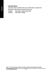
English Video BIOS Shadow It determines whether video BIOS is desibled. (Note) This item will increase the video speed. Video Shadow will show up when you install a processor which supports this function. GA-7CN700ID Motherboard - 26 - Enabled Video shadow is enabled .(Default Value) Disabled Video shadow is able to copy to RAM, however, it isoptional from chipset design.
English Video BIOS Shadow It determines whether video BIOS is desibled. (Note) This item will increase the video speed. Video Shadow will show up when you install a processor which supports this function. GA-7CN700ID Motherboard - 26 - Enabled Video shadow is enabled .(Default Value) Disabled Video shadow is able to copy to RAM, however, it isoptional from chipset design.

Manual
Page 28
... / Bank leterleve / Precharge to Active (Trp) / Active to CMD (Trcd) / REP to ACT/ REF(Trfc) / ACT(0) to 2T/3T/4T/5T. (Default value:4T) GA-7CN700ID Motherboard - 28 - Write Recovery Time (Twr) Set write recovery time to ACT(1) (TRRD) .Users can adjust these items based on their requirements. Bank Interleave Set bank...
... / Bank leterleve / Precharge to Active (Trp) / Active to CMD (Trcd) / REP to ACT/ REF(Trfc) / ACT(0) to 2T/3T/4T/5T. (Default value:4T) GA-7CN700ID Motherboard - 28 - Write Recovery Time (Twr) Set write recovery time to ACT(1) (TRRD) .Users can adjust these items based on their requirements. Bank Interleave Set bank...

Manual
Page 32
... 2E8/IRQ3. 4F8/IRQ5 Enable onboard Serial port 3 and address is 4F8/IRQ5. 4E8/IRQ7 Enable onboard Serial port 3 and address is 4E8/IRQ7. GA-7CN700ID Motherboard - 32 - Disabled Disable onboard Serial port 2. Onboard Serial Port 3 Auto BIOS will automatically setup the Serial port 4 address. 3F8/IRQ4 Enable onboard Serial port 4 and...
... 2E8/IRQ3. 4F8/IRQ5 Enable onboard Serial port 3 and address is 4F8/IRQ5. 4E8/IRQ7 Enable onboard Serial port 3 and address is 4E8/IRQ7. GA-7CN700ID Motherboard - 32 - Disabled Disable onboard Serial port 2. Onboard Serial Port 3 Auto BIOS will automatically setup the Serial port 4 address. 3F8/IRQ4 Enable onboard Serial port 4 and...


