8511725 - Gateway Service Guide
Page 3
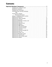
... the cooling assembly 14 Replacing the processor 19 Replacing the IEEE 802.11 wireless card 22 Replacing the hard drive 26 Replacing the keyboard cover 29 Replacing the keyboard 31 Replacing the CMOS battery 36 Replacing the LCD panel assembly 38 Replacing the LCD panel inverter 42 Replacing the LCD panel 46...
... the cooling assembly 14 Replacing the processor 19 Replacing the IEEE 802.11 wireless card 22 Replacing the hard drive 26 Replacing the keyboard cover 29 Replacing the keyboard 31 Replacing the CMOS battery 36 Replacing the LCD panel assembly 38 Replacing the LCD panel inverter 42 Replacing the LCD panel 46...
8511725 - Gateway Service Guide
Page 5
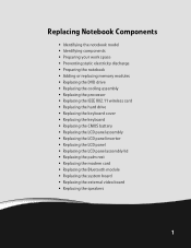
... the cooling assembly • Replacing the processor • Replacing the IEEE 802.11 wireless card • Replacing the hard drive • Replacing the keyboard cover • Replacing the keyboard • Replacing the CMOS battery • Replacing the LCD panel assembly • Replacing the LCD panel inverter • Replacing the LCD panel •...
... the cooling assembly • Replacing the processor • Replacing the IEEE 802.11 wireless card • Replacing the hard drive • Replacing the keyboard cover • Replacing the keyboard • Replacing the CMOS battery • Replacing the LCD panel assembly • Replacing the LCD panel inverter • Replacing the LCD panel •...
8511725 - Gateway Service Guide
Page 7
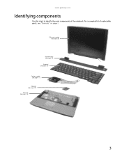
www.gateway.com Identifying components Use this chart to identify the main components of replaceable parts, see page 56) 3 For a complete list of the notebook. LCD panel assembly (see page 38) Keyboard cover (see page 29) Keyboard (see page 31) Cooling assembly (see page 11) Processor (see page 19) Palm rest (see "Contents" on page i.
www.gateway.com Identifying components Use this chart to identify the main components of replaceable parts, see page 56) 3 For a complete list of the notebook. LCD panel assembly (see page 38) Keyboard cover (see page 29) Keyboard (see page 31) Cooling assembly (see page 11) Processor (see page 19) Palm rest (see "Contents" on page i.
8511725 - Gateway Service Guide
Page 11
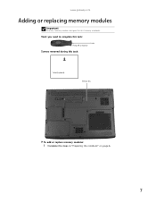
www.gateway.com Adding or replacing memory modules Important Use only memory modules designed for this task: 1 black (keyboard) Memory bay To add or replace memory modules: 1 Complete the steps in "Preparing the notebook" on page 6. 7 Tools you need to complete this task: Phillips #0 screwdriver Screws removed during this Gateway notebook.
www.gateway.com Adding or replacing memory modules Important Use only memory modules designed for this task: 1 black (keyboard) Memory bay To add or replace memory modules: 1 Complete the steps in "Preparing the notebook" on page 6. 7 Tools you need to complete this task: Phillips #0 screwdriver Screws removed during this Gateway notebook.
8511725 - Gateway Service Guide
Page 12
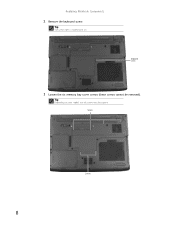
Screws Screws 8 Replacing Notebook Components 2 Remove the keyboard screw. Keyboard screw 3 Loosen the six memory bay cover screws (these screws cannot be captive. Tip The screw hole is marked with a K. Tip Depending on your model, not all screws may be removed).
Screws Screws 8 Replacing Notebook Components 2 Remove the keyboard screw. Keyboard screw 3 Loosen the six memory bay cover screws (these screws cannot be captive. Tip The screw hole is marked with a K. Tip Depending on your model, not all screws may be removed).

8511725 - Gateway Service Guide
Page 14
Replacing Notebook Components 6 Pull the memory module out of the slot. 7 Hold the new or replacement module at a 30-degree angle and press it can only be inserted in the memory bay. 8 Replace the memory bay cover, then tighten the cover screws. 9 Replace the keyboard screw. Tip The screw hole is keyed so it into the empty memory slot. If the module does not fit, make sure that the notch in the module lines up with a K. 10 This module is marked with the tab in one direction.
Replacing Notebook Components 6 Pull the memory module out of the slot. 7 Hold the new or replacement module at a 30-degree angle and press it can only be inserted in the memory bay. 8 Replace the memory bay cover, then tighten the cover screws. 9 Replace the keyboard screw. Tip The screw hole is keyed so it into the empty memory slot. If the module does not fit, make sure that the notch in the module lines up with a K. 10 This module is marked with the tab in one direction.
8511725 - Gateway Service Guide
Page 15
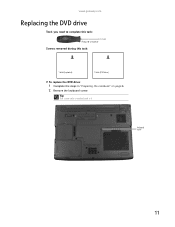
Tip The screw hole is marked with a K. Keyboard screw 11 www.gateway.com Replacing the DVD drive Tools you need to complete this task: Phillips #0 screwdriver Screws removed during this task: 1 black (keyboard) 1 black (DVD drive) To replace the DVD drive: 1 Complete the steps in "Preparing the notebook" on page 6. 2 Remove the keyboard screw.
Tip The screw hole is marked with a K. Keyboard screw 11 www.gateway.com Replacing the DVD drive Tools you need to complete this task: Phillips #0 screwdriver Screws removed during this task: 1 black (keyboard) 1 black (DVD drive) To replace the DVD drive: 1 Complete the steps in "Preparing the notebook" on page 6. 2 Remove the keyboard screw.
8511725 - Gateway Service Guide
Page 17
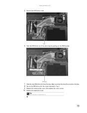
www.gateway.com 5 Remove the DVD drive screw. Make sure that the drive fits securely in the bay. 8 Secure the DVD drive with a K. 13 Screw 6 Slide the DVD drive out of the drive bay by pushing on the DVD bracket. Tip The screw hole is marked with the screw removed in Step 5. 9 Replace the memory bay cover, then tighten the cover screws. 10 Replace the keyboard screw. DVD bracket 7 Slide the new DVD drive into the drive bay.
www.gateway.com 5 Remove the DVD drive screw. Make sure that the drive fits securely in the bay. 8 Secure the DVD drive with a K. 13 Screw 6 Slide the DVD drive out of the drive bay by pushing on the DVD bracket. Tip The screw hole is marked with the screw removed in Step 5. 9 Replace the memory bay cover, then tighten the cover screws. 10 Replace the keyboard screw. DVD bracket 7 Slide the new DVD drive into the drive bay.

8511725 - Gateway Service Guide
Page 18
Replacing Notebook Components Replacing the cooling assembly Tools you need to complete this task: Phillips #0 screwdriver Additional materials you may need to complete this task: • X-23-7762 thermal grease Screws removed during this task: 1 black (keyboard) To replace the cooling assembly: 1 Complete the steps in "Preparing the notebook" on page 6. 2 Remove the keyboard screw. Keyboard screw 14 Tip The screw hole is marked with a K.
Replacing Notebook Components Replacing the cooling assembly Tools you need to complete this task: Phillips #0 screwdriver Additional materials you may need to complete this task: • X-23-7762 thermal grease Screws removed during this task: 1 black (keyboard) To replace the cooling assembly: 1 Complete the steps in "Preparing the notebook" on page 6. 2 Remove the keyboard screw. Keyboard screw 14 Tip The screw hole is marked with a K.
8511725 - Gateway Service Guide
Page 22
Tip The screw hole is marked with the numbers 1 through 4 next to them in numerical order. Important The number of screws varies by model. 13 Replace the memory bay cover, then tighten the cover screws. 14 Replace the keyboard screw. Replacing Notebook Components 12 Tighten the three or four screws, in numerical order, in the holes that are stamped with a K. 18 Caution When tightening the cooling assembly's screws in the numbered holes, tighten them .
Tip The screw hole is marked with the numbers 1 through 4 next to them in numerical order. Important The number of screws varies by model. 13 Replace the memory bay cover, then tighten the cover screws. 14 Replace the keyboard screw. Replacing Notebook Components 12 Tighten the three or four screws, in numerical order, in the holes that are stamped with a K. 18 Caution When tightening the cooling assembly's screws in the numbered holes, tighten them .
8511725 - Gateway Service Guide
Page 23
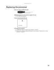
www.gateway.com Replacing the processor Tools you need to complete this task: Phillips #0 screwdriver Additional materials you may need to complete this task: • X-23-7762 thermal grease Screws removed during this task: 1 black (keyboard) To replace the processor: 1 Complete the steps in "Preparing the notebook" on page 6. 2 Remove the cooling assembly by following the instructions in "Replacing the cooling assembly" on page 14. 19
www.gateway.com Replacing the processor Tools you need to complete this task: Phillips #0 screwdriver Additional materials you may need to complete this task: • X-23-7762 thermal grease Screws removed during this task: 1 black (keyboard) To replace the processor: 1 Complete the steps in "Preparing the notebook" on page 6. 2 Remove the cooling assembly by following the instructions in "Replacing the cooling assembly" on page 14. 19
8511725 - Gateway Service Guide
Page 33
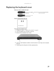
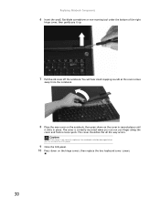
OR - Phillips #0 screwdriver Screws removed during this task: Flat-blade driver - Screw Screw 4 Insert the small flat-blade screwdriver under the bottom of each hinge cover and gently pry it up . 3 Remove the two keyboard cover screws. www.gateway.com Replacing the keyboard cover Tools you need to complete this task: Scribe or non-marring tool 2 black (keyboard cover) To replace the keyboard cover: 1 Complete the steps in "Preparing the notebook" on page 6. 2 Turn the notebook over so the top is facing up . 5 Carefully open the LCD panel to the fully opened position. 29
OR - Phillips #0 screwdriver Screws removed during this task: Flat-blade driver - Screw Screw 4 Insert the small flat-blade screwdriver under the bottom of each hinge cover and gently pry it up . 3 Remove the two keyboard cover screws. www.gateway.com Replacing the keyboard cover Tools you need to complete this task: Scribe or non-marring tool 2 black (keyboard cover) To replace the keyboard cover: 1 Complete the steps in "Preparing the notebook" on page 6. 2 Turn the notebook over so the top is facing up . 5 Carefully open the LCD panel to the fully opened position. 29
8511725 - Gateway Service Guide
Page 34
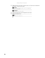
... you can run you try to close the LCD panel. 9 Close the LCD panel. 10 Press down on the hinge covers, then replace the two keyboard cover screws. 30 You will hear small snapping sounds as the cover comes away from the notebook. 8 Place the new cover on the notebook, then...
... you can run you try to close the LCD panel. 9 Close the LCD panel. 10 Press down on the hinge covers, then replace the two keyboard cover screws. 30 You will hear small snapping sounds as the cover comes away from the notebook. 8 Place the new cover on the notebook, then...
8511725 - Gateway Service Guide
Page 35
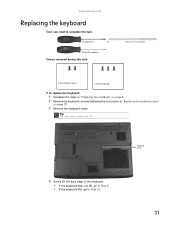
... task: Scribe or non-marring tool 2 black (keyboard cover) 1-3 black (keyboard) To replace the keyboard: 1 Complete the steps in "Preparing the notebook" on page 6. 2 Remove the keyboard cover by following the instructions in "Replacing the keyboard cover" on page 29. 3 Remove the keyboard screw. www.gateway.com Replacing the keyboard Tools you need to Step 10. 31 Tip...
... task: Scribe or non-marring tool 2 black (keyboard cover) 1-3 black (keyboard) To replace the keyboard: 1 Complete the steps in "Preparing the notebook" on page 6. 2 Remove the keyboard cover by following the instructions in "Replacing the keyboard cover" on page 29. 3 Remove the keyboard screw. www.gateway.com Replacing the keyboard Tools you need to Step 10. 31 Tip...
8511725 - Gateway Service Guide
Page 37
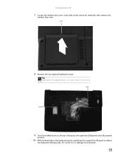
Tip Depending on the keyboard features, one or both of the keyboard raised, carefully push it toward the LCD panel to damage the LCD panel. 33 Screw Screw 9 Turn the notebook over so the top is facing up, then open the LCD panel to the fully opened position. 10 With the back edge of these screws may be removed), then remove the wireless bay cover. Be careful not to release the keyboard retaining tabs. www.gateway.com 7 Loosen the wireless bay cover screw (this screw cannot be absent. Screw 8 Remove the two optional keyboard screws.
Tip Depending on the keyboard features, one or both of the keyboard raised, carefully push it toward the LCD panel to damage the LCD panel. 33 Screw Screw 9 Turn the notebook over so the top is facing up, then open the LCD panel to the fully opened position. 10 With the back edge of these screws may be removed), then remove the wireless bay cover. Be careful not to release the keyboard retaining tabs. www.gateway.com 7 Loosen the wireless bay cover screw (this screw cannot be absent. Screw 8 Remove the two optional keyboard screws.

8511725 - Gateway Service Guide
Page 38
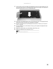
... now completely detached from the notebook. 14 Place the new keyboard keys-down on the notebook with the space bar away from the notebook. Be careful not to damage the LCD panel. 12 Lift the black keyboard connector clip, then remove the cable. Be careful not to touch or ...damage any other components. Replacing Notebook Components 11 Carefully rotate the keyboard toward the LCD panel until the keyboard is fully raised, insert the cable into the connector, then lower the black connector clip to lock the cable in place....
... now completely detached from the notebook. 14 Place the new keyboard keys-down on the notebook with the space bar away from the notebook. Be careful not to damage the LCD panel. 12 Lift the black keyboard connector clip, then remove the cable. Be careful not to touch or ...damage any other components. Replacing Notebook Components 11 Carefully rotate the keyboard toward the LCD panel until the keyboard is fully raised, insert the cable into the connector, then lower the black connector clip to lock the cable in place....
8511725 - Gateway Service Guide
Page 39
...hole is facing up, then replace the keyboard screws removed in Step 8. 21 Replace the memory bay cover and wireless network bay cover. 22 Replace the keyboard screw removed in Step 3. www.gateway.com 17 Insert the tabs on the front edge of the keyboard to seat the retaining tabs into their ...corresponding slots. 18 Gently press the keyboard down on page 29. 20 Turn the notebook over so...
...hole is facing up, then replace the keyboard screws removed in Step 8. 21 Replace the memory bay cover and wireless network bay cover. 22 Replace the keyboard screw removed in Step 3. www.gateway.com 17 Insert the tabs on the front edge of the keyboard to seat the retaining tabs into their ...corresponding slots. 18 Gently press the keyboard down on page 29. 20 Turn the notebook over so...
8511725 - Gateway Service Guide
Page 40
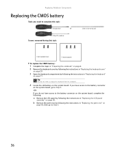
... board, go to Step 5. 36 If you do not need to complete this task: Scribe or non-marring tool 2 black (keyboard cover) 1-3 black (keyboard) To replace the CMOS battery: 1 Complete the steps in "Preparing the notebook" on page 6. 2 Remove the... keyboard cover by following the instructions in "Replacing the keyboard cover" on page 29. 3 Open the keyboard compartment by following the instructions in "Replacing the keyboard" on page 31. Replacing Notebook Components Replacing the CMOS battery Tools you need to...
... board, go to Step 5. 36 If you do not need to complete this task: Scribe or non-marring tool 2 black (keyboard cover) 1-3 black (keyboard) To replace the CMOS battery: 1 Complete the steps in "Preparing the notebook" on page 6. 2 Remove the... keyboard cover by following the instructions in "Replacing the keyboard cover" on page 29. 3 Open the keyboard compartment by following the instructions in "Replacing the keyboard" on page 31. Replacing Notebook Components Replacing the CMOS battery Tools you need to...
8511725 - Gateway Service Guide
Page 41
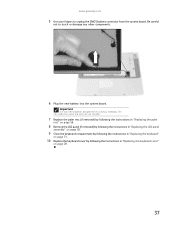
...fingers to touch or damage any other components. 6 Plug the new battery into the system board. Important Use only CMOS batteries designed for this Gateway notebook. The non-conductive sleeve and wires are not reusable. 7 Replace the palm rest (if removed) by following the instructions in "Replacing...in "Replacing the LCD panel assembly" on page 38. 9 Close the keyboard compartment by following the instructions in "Replacing the keyboard" on page 31. 10 Replace the keyboard cover by following the instructions in "Replacing the keyboard cover" on page 29. 37 Be careful not to unplug the CMOS ...
...fingers to touch or damage any other components. 6 Plug the new battery into the system board. Important Use only CMOS batteries designed for this Gateway notebook. The non-conductive sleeve and wires are not reusable. 7 Replace the palm rest (if removed) by following the instructions in "Replacing...in "Replacing the LCD panel assembly" on page 38. 9 Close the keyboard compartment by following the instructions in "Replacing the keyboard" on page 31. 10 Replace the keyboard cover by following the instructions in "Replacing the keyboard cover" on page 29. 37 Be careful not to unplug the CMOS ...

8511725 - Gateway Service Guide
Page 42
...the IEEE 802.11 wireless card" on page 22. 3 Remove the keyboard cover by following the instructions in "Replacing the keyboard cover" on page 29. 4 Open the keyboard compartment by following the instructions in "Replacing the keyboard" on page 6. 2 If the notebook has IEEE 802.11 wireless .... Replacing Notebook Components Replacing the LCD panel assembly Tools you need to complete this task: Scribe or non-marring tool 2 black (keyboard cover) 1-3 black (keyboard) 4 black (LCD panel hinges) To replace the LCD panel assembly: 1 Complete the steps in , unplug the antenna cables from the...
...the IEEE 802.11 wireless card" on page 22. 3 Remove the keyboard cover by following the instructions in "Replacing the keyboard cover" on page 29. 4 Open the keyboard compartment by following the instructions in "Replacing the keyboard" on page 6. 2 If the notebook has IEEE 802.11 wireless .... Replacing Notebook Components Replacing the LCD panel assembly Tools you need to complete this task: Scribe or non-marring tool 2 black (keyboard cover) 1-3 black (keyboard) 4 black (LCD panel hinges) To replace the LCD panel assembly: 1 Complete the steps in , unplug the antenna cables from the...


