
Service Guide
Page 4
Alerts you to do specific actions relevant to the accomplishment of additional information related to any damage that appear on screen. NOTE WARNING CAUTION IMPORTANT Gives bits and pieces of procedures. IV Gives precautionary measures to avoid possible hardware or software problems. Reminds you to the current topic. Conventions The following conventions are used in this manual: SCREEN MESSAGES Denotes actual messages that might result from doing or not doing specific actions.
Alerts you to do specific actions relevant to the accomplishment of additional information related to any damage that appear on screen. NOTE WARNING CAUTION IMPORTANT Gives bits and pieces of procedures. IV Gives precautionary measures to avoid possible hardware or software problems. Reminds you to the current topic. Conventions The following conventions are used in this manual: SCREEN MESSAGES Denotes actual messages that might result from doing or not doing specific actions.

Service Guide
Page 8
... Replacing the DIMM Module 119 Replacing the Hard Disk Drive Module 119 Replacing the Lower Covers 121 Replacing the Battery Pack 123 Troubleshooting 125 Common Problems 125 Power On Issue 126 No Display Issue 127 Random Loss of BIOS Settings 128 LCD Failure 129 Built-In Keyboard Failure 130 TouchPad Failure...
... Replacing the DIMM Module 119 Replacing the Hard Disk Drive Module 119 Replacing the Lower Covers 121 Replacing the Battery Pack 123 Troubleshooting 125 Common Problems 125 Power On Issue 126 No Display Issue 127 Random Loss of BIOS Settings 128 LCD Failure 129 Built-In Keyboard Failure 130 TouchPad Failure...

Service Guide
Page 9
...133 HDD Not Operating Correctly 134 USB Failure (Right up/down side 135 Other Failures 135 Intermittent Problems 136 Undetermined Problems 136 POST Code Reference Tables 137 Jumper and Connector Locations 141 Top View 141 Bottom View 142 ...Clearing Password Check and BIOS Recovery 143 Motherboard CMOS Discharge 143 BIOS Recovery by Crisis Disk 144 FRU (Field Replaceable Unit) List 147 Gateway LT31 Exploded Diagrams 148 Main Assembly 148 LCD Assembly 149 Gateway...
...133 HDD Not Operating Correctly 134 USB Failure (Right up/down side 135 Other Failures 135 Intermittent Problems 136 Undetermined Problems 136 POST Code Reference Tables 137 Jumper and Connector Locations 141 Top View 141 Bottom View 142 ...Clearing Password Check and BIOS Recovery 143 Motherboard CMOS Discharge 143 BIOS Recovery by Crisis Disk 144 FRU (Field Replaceable Unit) List 147 Gateway LT31 Exploded Diagrams 148 Main Assembly 148 LCD Assembly 149 Gateway...

Service Guide
Page 31
...). To activate the BIOS Utility, press F2 during POST to enter multi-boot menu. Press F2 to Chapter 4 Troubleshooting when problem arises. Navigating the BIOS Utility There are in any changes made and exit the BIOS Setup Utility. The default parameter of the... parameter values. Help for a particular menu are found in square brackets. Please note that system information is a hardware configuration program built into your computer's BIOS (Basic Input/ Output System). If you are six menu options: Information, Main, Advanced, Security, Power, Boot, and Exit. Follow ...
...). To activate the BIOS Utility, press F2 during POST to enter multi-boot menu. Press F2 to Chapter 4 Troubleshooting when problem arises. Navigating the BIOS Utility There are in any changes made and exit the BIOS Setup Utility. The default parameter of the... parameter values. Help for a particular menu are found in square brackets. Please note that system information is a hardware configuration program built into your computer's BIOS (Basic Input/ Output System). If you are six menu options: Information, Main, Advanced, Security, Power, Boot, and Exit. Follow ...

Service Guide
Page 135
... attempting to . Chapter 4 125 Use the following procedure as possible. 2. Obtain the failing symptoms in as much detail as a guide for computer problems. NOTE: The diagnostic tests are intended to test only Acer products. Symptoms (Verified) Go To Power On Issue Page 126 No Display Issue ... Failure Page 132 Internal Microphone Failure Page 133 USB Failure Page 135 Other Function Failure Page 135 4. Troubleshooting Chapter 4 Common Problems Use the following table with the verified symptom to determine which page to go to re-create the failure by running the ...
... attempting to . Chapter 4 125 Use the following procedure as possible. 2. Obtain the failing symptoms in as much detail as a guide for computer problems. NOTE: The diagnostic tests are intended to test only Acer products. Symptoms (Verified) Go To Power On Issue Page 126 No Display Issue ... Failure Page 132 Internal Microphone Failure Page 133 USB Failure Page 135 Other Function Failure Page 135 4. Troubleshooting Chapter 4 Common Problems Use the following table with the verified symptom to determine which page to go to re-create the failure by running the ...

Service Guide
Page 136
... actions one at a time to correct the problem. Remove any extension cables between the computer and the electrical outlet. Remove all external and non-essential hardware connected to the computer that are not necessary to boot the computer to the computer and the electrical outlet. 2. Remove any recently... Power On Issue If the system doesn't power on, perform the following actions one at a time to correct the problem. 1. Remove any surge protectors between the computer and the outlet. 3. If the Issue is properly connected to the failure point. 5. Check the power cable is...
... actions one at a time to correct the problem. Remove any extension cables between the computer and the electrical outlet. Remove all external and non-essential hardware connected to the computer that are not necessary to boot the computer to the computer and the electrical outlet. 2. Remove any recently... Power On Issue If the system doesn't power on, perform the following actions one at a time to correct the problem. 1. Remove any surge protectors between the computer and the outlet. 3. If the Issue is properly connected to the failure point. 5. Check the power cable is...

Service Guide
Page 137
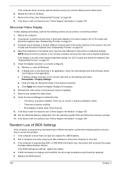
... Display doesn't work, perform the following actions one at least one of the following actions one at a time to correct the problem. 1. Go to the computer and switch between the internal display and the external display is by pressing Fn+F5 (on this notebook model, switching between the .... Drain any memory cards and CD/DVD discs. Remove any stored power by checking at a time to correct the problem. No troubleshooting step Ext. Make sure the computer has power by removing the power cable and battery and holding down the power button for specific model procedures. 2. DDRAM...
... Display doesn't work, perform the following actions one at least one of the following actions one at a time to correct the problem. 1. Go to the computer and switch between the internal display and the external display is by pressing Fn+F5 (on this notebook model, switching between the .... Drain any memory cards and CD/DVD discs. Remove any stored power by checking at a time to correct the problem. No troubleshooting step Ext. Make sure the computer has power by removing the power cable and battery and holding down the power button for specific model procedures. 2. DDRAM...
Service Guide
Page 138
... Other Devices. 9. Adjust the brightness to ensure the computer is missing from the operating system DVD and follow the onscreen prompts. 11. c. If HDD information is virus free. 3. Reseat the memory modules. 7. Reboot the computer. 2. See "Disassembly Process" on page 165. 10...165. Readjust if necessary. 6. See "Disassembly Process" on page 34. 5. Click and drag the Resolution slider to correct the problem. 1. If the computer is correctly configured: a. Replace the Motherboard. 128 Chapter 4 Run the Windows Memory Diagnostic from the BIOS, the drive may reduce...
... Other Devices. 9. Adjust the brightness to ensure the computer is missing from the operating system DVD and follow the onscreen prompts. 11. c. If HDD information is virus free. 3. Reseat the memory modules. 7. Reboot the computer. 2. See "Disassembly Process" on page 165. 10...165. Readjust if necessary. 6. See "Disassembly Process" on page 34. 5. Click and drag the Resolution slider to correct the problem. 1. If the computer is correctly configured: a. Replace the Motherboard. 128 Chapter 4 Run the Windows Memory Diagnostic from the BIOS, the drive may reduce...

Service Guide
Page 139
OK Check MB LCD connector and cable ? LCD Failure If the LCD fails, perform the following actions one at a time to correct the problem. plug LCD cable Swap M/B Chapter 4 129 If the Issue is still not resolved, see "Online Support Information" on page 165. Do not replace nondefective FRUs: Start OK Check LCD module? Swap NG LCD cable /LCD panel OK Reassemble NG Re- 6.
OK Check MB LCD connector and cable ? LCD Failure If the LCD fails, perform the following actions one at a time to correct the problem. plug LCD cable Swap M/B Chapter 4 129 If the Issue is still not resolved, see "Online Support Information" on page 165. Do not replace nondefective FRUs: Start OK Check LCD module? Swap NG LCD cable /LCD panel OK Reassemble NG Re- 6.

Service Guide
Page 140
No Replace Keyboard Replace mainboard 130 Chapter 4 Built-In Keyboard Failure If the built-in Keyboard fails, perform the following actions one at a time to correct the problem. Do not replace non-defective FRUs: Start Keyboard properly connected? No Disconnect and reconnect Keyboard functioning?
No Replace Keyboard Replace mainboard 130 Chapter 4 Built-In Keyboard Failure If the built-in Keyboard fails, perform the following actions one at a time to correct the problem. Do not replace non-defective FRUs: Start Keyboard properly connected? No Disconnect and reconnect Keyboard functioning?

Service Guide
Page 141
TouchPad Failure If the TouchPad doesn't work, perform the following actions one at a time to M/B OK Swap/Reassemble NG the T/P board or T/P FFC Swap M/B Chapter 4 131 Do not replace non-defective FRUs: Start OK Check M/B T/P FFC OK Check TouchPad Re-assemble the NG T/P FFC to correct the problem.
TouchPad Failure If the TouchPad doesn't work, perform the following actions one at a time to M/B OK Swap/Reassemble NG the T/P board or T/P FFC Swap M/B Chapter 4 131 Do not replace non-defective FRUs: Start OK Check M/B T/P FFC OK Check TouchPad Re-assemble the NG T/P FFC to correct the problem.

Service Guide
Page 142
...Speakers fail, perform the following actions one at a time to correct the problem. 1. Reboot the computer. 2. Ensure that all volume controls are experienced, perform the following actions one at a time to correct the problem. NOTE: If Speakers does not show, right-click on the taskbar and...OK Check Logic Upper/Logic upper Re-assemble the NG SPK cable to M/B OK Swap Logic NG lower/Logic upper Swap M/B Sound Problems If sound problems are set to the previous version, if updated recently. 4. Select Speakers and click Configure to configure the speakers. 132 Chapter 4...
...Speakers fail, perform the following actions one at a time to correct the problem. 1. Reboot the computer. 2. Ensure that all volume controls are experienced, perform the following actions one at a time to correct the problem. NOTE: If Speakers does not show, right-click on the taskbar and...OK Check Logic Upper/Logic upper Re-assemble the NG SPK cable to M/B OK Swap Logic NG lower/Logic upper Swap M/B Sound Problems If sound problems are set to the previous version, if updated recently. 4. Select Speakers and click Configure to configure the speakers. 132 Chapter 4...

Service Guide
Page 143
8. Reinstall the Operating System. 11. Internal Microphone Failure If the internal Microphone fails, perform the following actions one at a time to correct the problem. Do not replace non-defective FRUs: Start OK Check M/B Mic. Check that the microphone is not fixed, repeat the preceding steps and select an earlier .... cable OK Check MIC wire of LCD module Re-assemble the NG MIC cable to M/B OK Swap MIC wire of NG LCD module Swap M/B Microphone Problems If internal or external Microphones do no operate correctly, perform the following actions one at a time to correct the...
8. Reinstall the Operating System. 11. Internal Microphone Failure If the internal Microphone fails, perform the following actions one at a time to correct the problem. Do not replace non-defective FRUs: Start OK Check M/B Mic. Check that the microphone is not fixed, repeat the preceding steps and select an earlier .... cable OK Check MIC wire of LCD module Re-assemble the NG MIC cable to M/B OK Swap MIC wire of NG LCD module Swap M/B Microphone Problems If internal or external Microphones do no operate correctly, perform the following actions one at a time to correct the...

Service Guide
Page 144
.../DVD drive is not fixed, repeat the preceding steps and select an earlier time and date. 11. Select Startup Repair. h. Startup Repair attempts to ensure the computer is discovered, follow the onscreen information to correct the problem. 1. When complete, click Finish. Check the BIOS settings are required. For more information see "Online Support...
.../DVD drive is not fixed, repeat the preceding steps and select an earlier time and date. 11. Select Startup Repair. h. Startup Repair attempts to ensure the computer is discovered, follow the onscreen information to correct the problem. 1. When complete, click Finish. Check the BIOS settings are required. For more information see "Online Support...

Service Guide
Page 145
... whether the drive is ok. 3. USB Failure (Right up/down side) If the rightside USB port fails, perform the following general steps to correct the problem. Chapter 4 135 Do not replace non-defective FRUs: 1. Verify that the Test Fixture is OK. 2. Swap the mainboard and retest. Do not replace non-defective... Port, external MIC or Speakers, PCI Express Card, 5-in-1 Card Reader or Volume Wheel fail, perform the following actions one at a time to correct the problem.
... whether the drive is ok. 3. USB Failure (Right up/down side) If the rightside USB port fails, perform the following general steps to correct the problem. Chapter 4 135 Do not replace non-defective FRUs: 1. Verify that the Test Fixture is OK. 2. Swap the mainboard and retest. Do not replace non-defective... Port, external MIC or Speakers, PCI Express Card, 5-in-1 Card Reader or Volume Wheel fail, perform the following actions one at a time to correct the problem.

Service Guide
Page 146
... least 10 times. 2. If no more errors. If any problems are supported by a variety of the failure is detected, do not isolate non-defective FRU). Determine if the problem has changed. 6. Power-off the computer. 2. Visually check them for the system board in loop mode... at a time. Intermittent Problems Intermittent system hang problems can be considered only when a recurring problem exists. FRU replacement should be caused by ...
... least 10 times. 2. If no more errors. If any problems are supported by a variety of the failure is detected, do not isolate non-defective FRU). Determine if the problem has changed. 6. Power-off the computer. 2. Visually check them for the system board in loop mode... at a time. Intermittent Problems Intermittent system hang problems can be considered only when a recurring problem exists. FRU replacement should be caused by ...

Service Guide
Page 175
... Traveler's Warranty (ITW) • Returned material authorization procedures • An overview of all the support services we have included an Acrobat File to facilitate the problem-free downloading of telephone, fax and email contacts for all models • User's manuals • Training materials • Bios updates • Software utilities • Spare...
... Traveler's Warranty (ITW) • Returned material authorization procedures • An overview of all the support services we have included an Acrobat File to facilitate the problem-free downloading of telephone, fax and email contacts for all models • User's manuals • Training materials • Bios updates • Software utilities • Spare...

Service Guide
Page 177
... brightness hotkeys 12 Button Board Removing 56, 110 C Camera Board Removing 80 Replacing 91 caps lock on indicator 8 Card Reader Board Removing 61, 108 Common Problems 126 CPU Removing 77 Index CRT Board Removing 65 CRT Cable Removing 72, 96 D DIMM Module Removing 42, 119 Display 3 display hotkeys 12 E Euro Key... H Hard Disk Drive Module Removing 39, 119 HDD Cover Removing 121 Hibernation mode hotkey 12 Hinge Covers Removing 52, 114 Hot Keys 10 I Indicators 8 Intermittent Problems 136 Internal Microphone Failure 133 Internal Speaker Failure 132 J 167
... brightness hotkeys 12 Button Board Removing 56, 110 C Camera Board Removing 80 Replacing 91 caps lock on indicator 8 Card Reader Board Removing 61, 108 Common Problems 126 CPU Removing 77 Index CRT Board Removing 65 CRT Cable Removing 72, 96 D DIMM Module Removing 42, 119 Display 3 display hotkeys 12 E Euro Key... H Hard Disk Drive Module Removing 39, 119 HDD Cover Removing 121 Hibernation mode hotkey 12 Hinge Covers Removing 52, 114 Hot Keys 10 I Indicators 8 Intermittent Problems 136 Internal Microphone Failure 133 Internal Speaker Failure 132 J 167

Service Guide
Page 179
Built-in KB Failure 130 Internal Microphone 133 Internal Speakers 132 LCD Failure 129 No Display 127 ODD 135 Other Failures 135 Power On 126 Touch Pad 131 USB 135 U Undetermined Problems 136 Upper Cover Removing 53, 111 USB Failure (Rightside) 135 utility BIOS 21-29 V volume hotkeys 12 W Windows 2000 Environment Test 162 WLAN Board Removing 44, 116 169
Built-in KB Failure 130 Internal Microphone 133 Internal Speakers 132 LCD Failure 129 No Display 127 ODD 135 Other Failures 135 Power On 126 Touch Pad 131 USB 135 U Undetermined Problems 136 Upper Cover Removing 53, 111 USB Failure (Rightside) 135 utility BIOS 21-29 V volume hotkeys 12 W Windows 2000 Environment Test 162 WLAN Board Removing 44, 116 169


