User Guide
Page 4
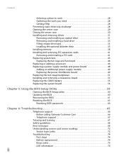
... Replacing the fan cage and fan board 44 Replacing or adding a processor 46 Replacing a power supply module and power board 48 Adding an additional power supply module 49 Replacing the power distribution board 49 Replacing the hot-swap backplanes 51 Installing and removing a mezzanine board 53 ...Recovering the BIOS 61 Resetting the BIOS 63 Resetting BIOS passwords 64 Chapter 6: Troubleshooting 65 Telephone support 66 Before calling Gateway Customer Care 66 Telephone support 67 Tutoring and training 67 Safety guidelines 68 Error messages 68 Understanding sensors and sensor ...
... Replacing the fan cage and fan board 44 Replacing or adding a processor 46 Replacing a power supply module and power board 48 Adding an additional power supply module 49 Replacing the power distribution board 49 Replacing the hot-swap backplanes 51 Installing and removing a mezzanine board 53 ...Recovering the BIOS 61 Resetting the BIOS 63 Resetting BIOS passwords 64 Chapter 6: Troubleshooting 65 Telephone support 66 Before calling Gateway Customer Care 66 Telephone support 67 Tutoring and training 67 Safety guidelines 68 Error messages 68 Understanding sensors and sensor ...

User Guide
Page 9
www.gateway.com Back Connectors and LEDs PS/2 mouse port PS/2 keyboard port Dual USB ports Serial port VGA port ID LED Dual NIC connectors (RJ-45) Management port (RJ-45) Back AC power connector Power supply status LED Power supply module Case cover thumbscrew Case cover thumbscrew 3
www.gateway.com Back Connectors and LEDs PS/2 mouse port PS/2 keyboard port Dual USB ports Serial port VGA port ID LED Dual NIC connectors (RJ-45) Management port (RJ-45) Back AC power connector Power supply status LED Power supply module Case cover thumbscrew Case cover thumbscrew 3
User Guide
Page 10
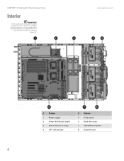
www.gateway.com # Feature 1 Power supply 2 Power distribution board 3 System fans (hot swap) 4 5.25" device bays # Feature 5 Front panel 6 Hard drive bays 7 SAS/SATA backplane 8 System board 4 Server components with green handles or retention locks can only be hot swapped while the server is turned off. CHAPTER 1: Checking Out Your Gateway Server Interior Important Server components with blue handles or retention locks can be removed when the server is on.
www.gateway.com # Feature 1 Power supply 2 Power distribution board 3 System fans (hot swap) 4 5.25" device bays # Feature 5 Front panel 6 Hard drive bays 7 SAS/SATA backplane 8 System board 4 Server components with green handles or retention locks can only be hot swapped while the server is turned off. CHAPTER 1: Checking Out Your Gateway Server Interior Important Server components with blue handles or retention locks can be removed when the server is on.

User Guide
Page 12
CHAPTER 1: Checking Out Your Gateway Server www.gateway.com # Feature # Feature 7 Management port (RJ-45) (J30) 32 Not used 8 Dual NIC connector (RJ-... 14 System fan connector (J4) 39 IDE connector (J54) 15 System fan connector (J3) 40 Floppy connector (J49) 16 Main power connector (J7) 41 PCI-X mezzanine board connector (J44) 17 DIMM 1 socket (J11) 42 Front panel USB connector (J56) 18...DIMM 7 socket (J23) 48 1x2 pin system configuration jumper 1 (J58) 24 DIMM 8 socket (J26) 25 Power supply I2C connector (J8) 49 2x5 pin system configuration jumper 2 (J59) 50 Battery (B1) 6
CHAPTER 1: Checking Out Your Gateway Server www.gateway.com # Feature # Feature 7 Management port (RJ-45) (J30) 32 Not used 8 Dual NIC connector (RJ-... 14 System fan connector (J4) 39 IDE connector (J54) 15 System fan connector (J3) 40 Floppy connector (J49) 16 Main power connector (J7) 41 PCI-X mezzanine board connector (J44) 17 DIMM 1 socket (J11) 42 Front panel USB connector (J56) 18...DIMM 7 socket (J23) 48 1x2 pin system configuration jumper 1 (J58) 24 DIMM 8 socket (J26) 25 Power supply I2C connector (J8) 49 2x5 pin system configuration jumper 2 (J59) 50 Battery (B1) 6

User Guide
Page 14
...) - LAN link for a description of system (front) enabled board Blue (back) Front panel Red Off - NIC activity LED 1 (Off ) - Power supply good and receiving power Red (On) - CHAPTER 1: Checking Out Your Gateway Server www.gateway.com LED information See the following table for any NIC Blinking - Hard drive rebuilding Off - No hard drive Front panel...
...) - LAN link for a description of system (front) enabled board Blue (back) Front panel Red Off - NIC activity LED 1 (Off ) - Power supply good and receiving power Red (On) - CHAPTER 1: Checking Out Your Gateway Server www.gateway.com LED information See the following table for any NIC Blinking - Hard drive rebuilding Off - No hard drive Front panel...
User Guide
Page 18
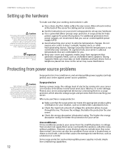
...Setting Up Your Server www.gateway.com Setting up your hardware. ■ Use a grounded (three-prong) surge protector. Important Keep the server boxes and packing material in voltage from power source problems Surge protectors, line conditioners, and uninterruptible power supplies can increase to direct sunlight...warranty. Line conditioners A line conditioner protects your server from the small fluctuations in case you have a modem, use an uninterruptible power supply (UPS). ■ Avoid subjecting your surge protector, UPS, or wall outlet, do not attempt to the server may cause...
...Setting Up Your Server www.gateway.com Setting up your hardware. ■ Use a grounded (three-prong) surge protector. Important Keep the server boxes and packing material in voltage from power source problems Surge protectors, line conditioners, and uninterruptible power supplies can increase to direct sunlight...warranty. Line conditioners A line conditioner protects your server from the small fluctuations in case you have a modem, use an uninterruptible power supply (UPS). ■ Avoid subjecting your surge protector, UPS, or wall outlet, do not attempt to the server may cause...

User Guide
Page 19
... You cannot run your server running temporarily during a total power failure. www.gateway.com Protecting from power source problems Uninterruptible power supplies Use an uninterruptible power supply (UPS) to protect your server from data loss during a power failure and lets you turn off the server, then unplug the power cord(s) and all other cables connected to disengage the tabs... server case" on page 29. 5 Close the bezel door, then pull out on the three retaining tabs on page 28. To buy a UPS, visit accessories.gateway.com.
... You cannot run your server running temporarily during a total power failure. www.gateway.com Protecting from power source problems Uninterruptible power supplies Use an uninterruptible power supply (UPS) to protect your server from data loss during a power failure and lets you turn off the server, then unplug the power cord(s) and all other cables connected to disengage the tabs... server case" on page 29. 5 Close the bezel door, then pull out on the three retaining tabs on page 28. To buy a UPS, visit accessories.gateway.com.

User Guide
Page 33
CHAPTER 4 Installing Components • Preparing to install components • Preventing static electricity discharge • Opening the server case • Closing the server case • Installing and removing drives • Installing memory • Installing and removing PCI expansion cards • Replacing system fans • Replacing or adding a processor • Replacing a power supply module and power board • Replacing the hot-swap backplanes • Replacing the CMOS battery • Replacing the system board 27
CHAPTER 4 Installing Components • Preparing to install components • Preventing static electricity discharge • Opening the server case • Closing the server case • Installing and removing drives • Installing memory • Installing and removing PCI expansion cards • Replacing system fans • Replacing or adding a processor • Replacing a power supply module and power board • Replacing the hot-swap backplanes • Replacing the CMOS battery • Replacing the system board 27

User Guide
Page 34
... surface on the back of the power supply. Gathering the tools you may need help from the server. ■ Wear a grounding wrist strap (available at most electronics stores) and attach it to a bare metal part of the server. CHAPTER 4: Installing Components Preparing to install components www.gateway.com Selecting a place to work on...
... surface on the back of the power supply. Gathering the tools you may need help from the server. ■ Wear a grounding wrist strap (available at most electronics stores) and attach it to a bare metal part of the server. CHAPTER 4: Installing Components Preparing to install components www.gateway.com Selecting a place to work on...

User Guide
Page 51
www.gateway.com Replacing system fans 7 Slide the fan board away from the power supply (5), then remove it from the chassis (6). 8 Place the new fan board on the standoffs in the chassis, then slide it toward the power supply to lock it down. 9 Tighten the thumbscrew to secure the fan board in place. 10 Connect the...
www.gateway.com Replacing system fans 7 Slide the fan board away from the power supply (5), then remove it from the chassis (6). 8 Place the new fan board on the standoffs in the chassis, then slide it toward the power supply to lock it down. 9 Tighten the thumbscrew to secure the fan board in place. 10 Connect the...

User Guide
Page 54
... that it so that is damaged, you should service the power supplies. CHAPTER 4: Installing Components www.gateway.com Caution The heatsink has Thermal Interface Material (TIM) located on the bottom of the two power supplies fails, the other power supply supports the server while you replace the failed power supply. If this server contain no user-serviceable parts. It...
... that it so that is damaged, you should service the power supplies. CHAPTER 4: Installing Components www.gateway.com Caution The heatsink has Thermal Interface Material (TIM) located on the bottom of the two power supplies fails, the other power supply supports the server while you replace the failed power supply. If this server contain no user-serviceable parts. It...
User Guide
Page 55
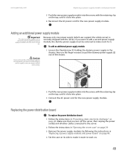
www.gateway.com Replacing a power supply module and power board 5 Push the new power supply module into the server, with the retaining clip on the top, until it clicks into place. 6 Reconnect the AC power cord for the new power supply module. To add an additional power supply module: Caution If you remove either of the power supplies for any reason, you must be...
www.gateway.com Replacing a power supply module and power board 5 Push the new power supply module into the server, with the retaining clip on the top, until it clicks into place. 6 Reconnect the AC power cord for the new power supply module. To add an additional power supply module: Caution If you remove either of the power supplies for any reason, you must be...

User Guide
Page 56
... board" on page 30. 50 CHAPTER 4: Installing Components www.gateway.com 5 Disconnect the main power, CPU power, backplane power, I2C power, and midplane power cables. Important Make sure that the power supply cable box is connected to the power supply connector(s) on the power supply(ies). 8 Align the new power distribution board with the power supply cage and the standoffs, then push it down onto...
... board" on page 30. 50 CHAPTER 4: Installing Components www.gateway.com 5 Disconnect the main power, CPU power, backplane power, I2C power, and midplane power cables. Important Make sure that the power supply cable box is connected to the power supply connector(s) on the power supply(ies). 8 Align the new power distribution board with the power supply cage and the standoffs, then push it down onto...

User Guide
Page 57
www.gateway.com Replacing the hot-swap backplanes Replacing the hot-swap backplanes Caution The hot-swap backplane is not hot-swappable. Make sure that you do ... case" on page 29. 3 Unlock the bezel (if necessary) and remove it by pulling it easier to the server, and remove the AC power cord(s) from the power supply or wall outlet. Caution Pressing or pulling on any cables as you install the backplane. 9 Loosen the thumbscrew (3) holding the backplane on the back...
www.gateway.com Replacing the hot-swap backplanes Replacing the hot-swap backplanes Caution The hot-swap backplane is not hot-swappable. Make sure that you do ... case" on page 29. 3 Unlock the bezel (if necessary) and remove it by pulling it easier to the server, and remove the AC power cord(s) from the power supply or wall outlet. Caution Pressing or pulling on any cables as you install the backplane. 9 Loosen the thumbscrew (3) holding the backplane on the back...

User Guide
Page 79
www.gateway.com Understanding sensors and sensor readings Sensor type Fan Voltage Voltage Voltage Voltage Voltage Voltage Voltage Voltage Voltage Voltage Voltage Voltage Temperature Temperature Temperature Temperature Temperature Temperature Temperature Processor Processor Physical Security Button Power Supply Power Supply Power Supply Power Unit Watchdog 2 Sys. C 22 deg. C 22 deg. ...ESB2 Ambient CPU0 State CPU1 State Chas Intrusion UID BTN PS1 STATUS PS2 STATUS PS REDUNDANCY Power Unit Watchdog2 SYS EVENT Sensor status Normal operating range Normal operating range Normal operating range ...
www.gateway.com Understanding sensors and sensor readings Sensor type Fan Voltage Voltage Voltage Voltage Voltage Voltage Voltage Voltage Voltage Voltage Voltage Voltage Temperature Temperature Temperature Temperature Temperature Temperature Temperature Processor Processor Physical Security Button Power Supply Power Supply Power Supply Power Unit Watchdog 2 Sys. C 22 deg. C 22 deg. ...ESB2 Ambient CPU0 State CPU1 State Chas Intrusion UID BTN PS1 STATUS PS2 STATUS PS REDUNDANCY Power Unit Watchdog2 SYS EVENT Sensor status Normal operating range Normal operating range Normal operating range ...
User Guide
Page 83
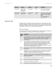
.... Enable IRQ-0 in the event of a system hang during the POST portion of the system Power supply Identify power status LED supply fault Location Front panel Power supply module Color Blue Green or Red Description Off - Init Local APIC C1 Set up application processors.... troubleshooting information in PIC for system timer interrupt. Power is being done on POST entry and GPNV area. Initialize BIOS, POST, Runtime data area. www.gateway.com Troubleshooting LED Name Function Power LED Identify the power state of the BIOS: Check Description point 03 Disable...
.... Enable IRQ-0 in the event of a system hang during the POST portion of the system Power supply Identify power status LED supply fault Location Front panel Power supply module Color Blue Green or Red Description Off - Init Local APIC C1 Set up application processors.... troubleshooting information in PIC for system timer interrupt. Power is being done on POST entry and GPNV area. Initialize BIOS, POST, Runtime data area. www.gateway.com Troubleshooting LED Name Function Power LED Identify the power state of the BIOS: Check Description point 03 Disable...

User Guide
Page 91
...9632; Check the port and cable for brighter colors and greater luminescence. A horizontal line or wire is a critical part of error. www.gateway.com Monitor Power Troubleshooting Your server is running but there is no picture ■ Adjust the brightness and contrast controls to the center position. ■ ... to an electrical outlet, turned on, and working device, such as a lamp, into a surge protector or UPS, make sure that the power supply module cage cable is turned on, but you may use thin damper wires, located approximately 1/3 of the way from the upper and lower screen...
...9632; Check the port and cable for brighter colors and greater luminescence. A horizontal line or wire is a critical part of error. www.gateway.com Monitor Power Troubleshooting Your server is running but there is no picture ■ Adjust the brightness and contrast controls to the center position. ■ ... to an electrical outlet, turned on, and working device, such as a lamp, into a surge protector or UPS, make sure that the power supply module cage cable is turned on, but you may use thin damper wires, located approximately 1/3 of the way from the upper and lower screen...
User Guide
Page 94
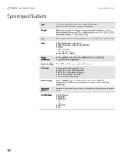
APPENDIX A: Server Specifications System specifications www.gateway.com Case 17 × 8.66 × 27.56 inches (432 × 220 × 700 mm) Convertible from tower to rack-mountable Weight Minimum weight (no bezel, power supplies, hard drives, optical drive, diskette drive, fans, PCAs...; 2 PCI-X 64-bit/66 MHz slots ■ 1 PCI 32-bit/33 MHz slot Power supply One 725 W hot-swap, power supply module (standard) Additional 725 W hot-swap redundant power supply module (optional) Operating systems Supports Windows Server 2003 and Windows Small Business Server 2003 Certifications ■...
APPENDIX A: Server Specifications System specifications www.gateway.com Case 17 × 8.66 × 27.56 inches (432 × 220 × 700 mm) Convertible from tower to rack-mountable Weight Minimum weight (no bezel, power supplies, hard drives, optical drive, diskette drive, fans, PCAs...; 2 PCI-X 64-bit/66 MHz slots ■ 1 PCI 32-bit/33 MHz slot Power supply One 725 W hot-swap, power supply module (standard) Additional 725 W hot-swap redundant power supply module (optional) Operating systems Supports Windows Server 2003 and Windows Small Business Server 2003 Certifications ■...

User Guide
Page 116
... you operate your system. Your Gateway system is replaced incorrectly. Such areas include patient care areas of information technology equipment. Setting up the system on the products plugged into an outlet, contact an electrician to meet the latest standards for your area. Warning This unit has two power supplies. To avoid electrical shock...
... you operate your system. Your Gateway system is replaced incorrectly. Such areas include patient care areas of information technology equipment. Setting up the system on the products plugged into an outlet, contact an electrician to meet the latest standards for your area. Warning This unit has two power supplies. To avoid electrical shock...
User Guide
Page 122
... 12 location drive bays 4 fan module 4 memory slots 4 PCI riser assembly 4 power supply cage 4 processor air duct 4 lock Kensington 3 key 2, 13, 29 location 2, 3 M Main menu BIOS Setup utility 60 maintenance cleaning 20 cleaning case 20 cleaning keyboard 21 cleaning screen 21 Gateway System Manager 22 general guidelines 20 recording BIOS configuration 21 master...
... 12 location drive bays 4 fan module 4 memory slots 4 PCI riser assembly 4 power supply cage 4 processor air duct 4 lock Kensington 3 key 2, 13, 29 location 2, 3 M Main menu BIOS Setup utility 60 maintenance cleaning 20 cleaning case 20 cleaning keyboard 21 cleaning screen 21 Gateway System Manager 22 general guidelines 20 recording BIOS configuration 21 master...