User Guide
Page 3
... power-on self-test 16 Turning off your server 16 Setting up the operating system 17 Initial hardware settings 17 Chapter 3: Maintaining Your Server 19 Caring for your server 20 Cleaning your server 20 Preparing for system recovery 21 Recording the BIOS configuration 21 System administration 22 Gateway System Manager 22 Server security 22 Identifying your server 23 Updating the baseboard management controller firmware 23 Using your Server Companion DVD 24 Server Companion DVD contents 24 Viewing documents 24 Installing drivers...
... power-on self-test 16 Turning off your server 16 Setting up the operating system 17 Initial hardware settings 17 Chapter 3: Maintaining Your Server 19 Caring for your server 20 Cleaning your server 20 Preparing for system recovery 21 Recording the BIOS configuration 21 System administration 22 Gateway System Manager 22 Server security 22 Identifying your server 23 Updating the baseboard management controller firmware 23 Using your Server Companion DVD 24 Server Companion DVD contents 24 Viewing documents 24 Installing drivers...
User Guide
Page 4
... fan board 44 Replacing or adding a processor 46 Replacing a power supply module and power board 48 Adding an additional power supply module 49 Replacing the power distribution board 49 Replacing the hot-swap backplanes 51 Installing and removing a mezzanine board 53 Replacing the CMOS battery 55 Replacing the system board 56 Chapter 5: Using the BIOS Setup Utility 59 Opening the BIOS Setup utility 60 Updating the BIOS 60 Recovering the BIOS 61 Resetting the BIOS 63 Resetting BIOS passwords 64 Chapter 6: Troubleshooting 65 Telephone support 66 Before calling Gateway Customer...
... fan board 44 Replacing or adding a processor 46 Replacing a power supply module and power board 48 Adding an additional power supply module 49 Replacing the power distribution board 49 Replacing the hot-swap backplanes 51 Installing and removing a mezzanine board 53 Replacing the CMOS battery 55 Replacing the system board 56 Chapter 5: Using the BIOS Setup Utility 59 Opening the BIOS Setup utility 60 Updating the BIOS 60 Recovering the BIOS 61 Resetting the BIOS 63 Resetting BIOS passwords 64 Chapter 6: Troubleshooting 65 Telephone support 66 Before calling Gateway Customer...

User Guide
Page 22
... the power button. - See your operating system's documentation for instructions on . To remove AC power from the wall outlet or power source. To turn off the server: 1 See the operating system's documentation or online help for troubleshooting information. Understanding the power-on self-test When you turn on shutting down procedure instead of the power loss, contact Gateway Customer Care. For more information, see "Error messages" on page 68 and "Beep codes...
... the power button. - See your operating system's documentation for instructions on . To remove AC power from the wall outlet or power source. To turn off the server: 1 See the operating system's documentation or online help for troubleshooting information. Understanding the power-on self-test When you turn on shutting down procedure instead of the power loss, contact Gateway Customer Care. For more information, see "Error messages" on page 68 and "Beep codes...

User Guide
Page 29
... system event log and sensor data records ■ Interfacing with the emergency management port to send alerts and interact with remote management systems ■ Fault resilient booting (the extent depends on the option selected) You should update the BMC firmware when Gateway Customer Care has instructed you are working on. For the System ID indicator to turn on, the server does not need to remove. 3 Enter the current password...
... system event log and sensor data records ■ Interfacing with the emergency management port to send alerts and interact with remote management systems ■ Fault resilient booting (the extent depends on the option selected) You should update the BMC firmware when Gateway Customer Care has instructed you are working on. For the System ID indicator to turn on, the server does not need to remove. 3 Enter the current password...
User Guide
Page 31
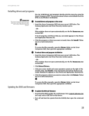
... a USB Disk-on the Server Companion DVD, then open automatically, run the file Runmenu.exe on the DVD. 2 Click Extract Drivers. 3 Click your Server Companion DVD Installing drivers and programs Important The Server Companion DVD's Gateway Application and Driver Recovery utility works only in the Drivers and Application Recovery list. 4 Click the program or driver you want to diskettes: 1 Insert the Server Companion DVD into your server's DVD drive. To access the files manually, open the Drivers folder on -key device. 2 Turn off and boot...
... a USB Disk-on the Server Companion DVD, then open automatically, run the file Runmenu.exe on the DVD. 2 Click Extract Drivers. 3 Click your Server Companion DVD Installing drivers and programs Important The Server Companion DVD's Gateway Application and Driver Recovery utility works only in the Drivers and Application Recovery list. 4 Click the program or driver you want to diskettes: 1 Insert the Server Companion DVD into your server's DVD drive. To access the files manually, open the Drivers folder on -key device. 2 Turn off and boot...

User Guide
Page 61
..., then remove the old battery. You can use a screwdriver to help lift the battery. 9 Make sure that you turn off your server, then follow the instructions in "Preventing static electricity discharge" on page 28. 5 Follow the instructions in "Opening the server case" on page 29. 6 Set the chassis on your server, then press F2 when the Gateway logo screen appears during startup. The BIOS Setup utility opens. 13...
..., then remove the old battery. You can use a screwdriver to help lift the battery. 9 Make sure that you turn off your server, then follow the instructions in "Preventing static electricity discharge" on page 28. 5 Follow the instructions in "Opening the server case" on page 29. 6 Set the chassis on your server, then press F2 when the Gateway logo screen appears during startup. The BIOS Setup utility opens. 13...
User Guide
Page 66
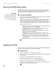
... download the BIOS update from Gateway, then install the new version from support.gateway.com. 5 Follow the instructions in the self-extracting BIOS update file. 6 Enter any custom BIOS settings on page 97. For more information, see "Server security" on page 22. ■ Server gives you access to settings for system management, console redirection, event log configuration, and fault-resilient boot settings. ■ Exit gives you access to options for "BIOS Settings" on your printout. 4 Download the BIOS update from a diskette. Changes...
... download the BIOS update from Gateway, then install the new version from support.gateway.com. 5 Follow the instructions in the self-extracting BIOS update file. 6 Enter any custom BIOS settings on page 97. For more information, see "Server security" on page 22. ■ Server gives you access to settings for system management, console redirection, event log configuration, and fault-resilient boot settings. ■ Exit gives you access to options for "BIOS Settings" on your printout. 4 Download the BIOS update from a diskette. Changes...
User Guide
Page 69
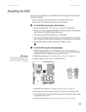
... Gateway logo screen appears during startup. To reset the BIOS using the power and reset buttons: 1 Print the appendix for four seconds or more, then press the power button while continuing to the server. 2 Follow the instructions in "Opening the server case" on page 29. 3 Install a jumper across pins 1-2 of the server. ■ Move the Clear CMOS jumper on the system board. To reset the BIOS using the system board jumper: 1 Follow the instructions in this guide...
... Gateway logo screen appears during startup. To reset the BIOS using the power and reset buttons: 1 Print the appendix for four seconds or more, then press the power button while continuing to the server. 2 Follow the instructions in "Opening the server case" on page 29. 3 Install a jumper across pins 1-2 of the server. ■ Move the Clear CMOS jumper on the system board. To reset the BIOS using the system board jumper: 1 Follow the instructions in this guide...
User Guide
Page 74
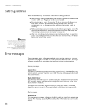
... that requires further troubleshooting. A multiple-bit corruption of memory over 1 MB. For more information about preventing damage from a particular device. Liquid has been spilled into your server and contact a qualified computer technician. Boot messages Boot Failure ... CHAPTER 6: Troubleshooting www.gateway.com Safety guidelines Warning To avoid bodily injury, do so is extremely dangerous. While troubleshooting your server, follow these safety guidelines: ■ Never remove the top panel...
... that requires further troubleshooting. A multiple-bit corruption of memory over 1 MB. For more information about preventing damage from a particular device. Liquid has been spilled into your server and contact a qualified computer technician. Boot messages Boot Failure ... CHAPTER 6: Troubleshooting www.gateway.com Safety guidelines Warning To avoid bodily injury, do so is extremely dangerous. While troubleshooting your server, follow these safety guidelines: ■ Never remove the top panel...

User Guide
Page 80
... unlikely, your new battery may need to remove the device, uninstall the device's software, then reinstall the device. ■ If an error message appears on the screen, write down the exact message before the problem started, review the installation procedures you performed and make sure that the colored cable edges are attached securely. Check your configuration settings. ■ When diagnosing problems, press the non-maskable interrupt (NMI) button to put the...
... unlikely, your new battery may need to remove the device, uninstall the device's software, then reinstall the device. ■ If an error message appears on the screen, write down the exact message before the problem started, review the installation procedures you performed and make sure that the colored cable edges are attached securely. Check your configuration settings. ■ When diagnosing problems, press the non-maskable interrupt (NMI) button to put the...
User Guide
Page 81
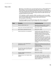
... error (processor exception error). Troubleshooting steps Reseat the memory modules or replace with modules you of error conditions. To eliminate the possibility of the processors if two are good. Install the cards one long tone followed by two short tones) during the power-on self-test (POST), the BIOS displays an error message that device. Remove the keyboard to Protected mode. One short beep indicates the BIOS will boot the operating system. The following table shows POST error beep codes. A processor...
... error (processor exception error). Troubleshooting steps Reseat the memory modules or replace with modules you of error conditions. To eliminate the possibility of the processors if two are good. Install the cards one long tone followed by two short tones) during the power-on self-test (POST), the BIOS displays an error message that device. Remove the keyboard to Protected mode. One short beep indicates the BIOS will boot the operating system. The following table shows POST error beep codes. A processor...
User Guide
Page 83
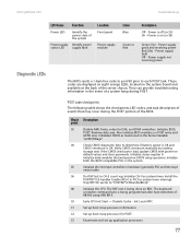
... default values and clear passwords. Initialize data variables that may occur during POST. Trap INT1Ch vector to each POST task. The BAT test is on the system board and available at the back of events that are displayed on eight orange LEDs, located on (or S0) Green (On) - The keyboard controller command byte is off (or S5) On - C5 Enumerate and set up boot strap processor for POST. Power supply fault...
... default values and clear passwords. Initialize data variables that may occur during POST. Trap INT1Ch vector to each POST task. The BAT test is on the system board and available at the back of events that are displayed on eight orange LEDs, located on (or S0) Green (On) - The keyboard controller command byte is off (or S5) On - C5 Enumerate and set up boot strap processor for POST. Power supply fault...
User Guide
Page 85
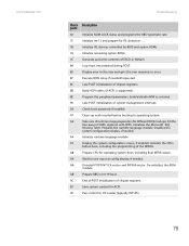
...-LOCK status and programs the KBD typematic rate. Initialize IPL devices controlled by BIOS and option ROMs. Initialize remaining option ROMs. Generate and write contents of chipset registers. Log errors encountered during POST. Execute BIOS setup if needed . Program the peripheral parameters. Fill the free area in Int 19 boot. Display the system configuration screen, if enabled. Prepare CPU for user input at config display, if needed before boot, including...
...-LOCK status and programs the KBD typematic rate. Initialize IPL devices controlled by BIOS and option ROMs. Initialize remaining option ROMs. Generate and write contents of chipset registers. Log errors encountered during POST. Execute BIOS setup if needed . Program the peripheral parameters. Fill the free area in Int 19 boot. Display the system configuration screen, if enabled. Prepare CPU for user input at config display, if needed before boot, including...

User Guide
Page 89
... instructions, see Using Your Server Companion DVD. ■ Make sure that the PCI slot option ROM is turned on page 31. www.gateway.com Optical drive Expansion cards Hard drive Troubleshooting Your server does not recognize an optical drive ■ Restart your server, then open ■ Press a straightened paper clip wire into the optical drive's manual eject hole. For more information, see "Installing and removing PCI expansion cards" on page 59. ■ Reinstall the device driver. Your server does...
... instructions, see Using Your Server Companion DVD. ■ Make sure that the PCI slot option ROM is turned on page 31. www.gateway.com Optical drive Expansion cards Hard drive Troubleshooting Your server does not recognize an optical drive ■ Restart your server, then open ■ Press a straightened paper clip wire into the optical drive's manual eject hole. For more information, see "Installing and removing PCI expansion cards" on page 59. ■ Reinstall the device driver. Your server does...

User Guide
Page 90
... "Installing memory" on page 84. If not, the drive may be defective. Memory errors were detected during server start up ■ Open your server and make sure that the memory modules are having problems with your Internet Service Provider (ISP) is corrupted" on page 38. ■ A memory module may need to the Internet ■ Make sure that your account with a SATA drive ■ For normal SATA drives (not SATA RAID), check the BIOS setup utility to...
... "Installing memory" on page 84. If not, the drive may be defective. Memory errors were detected during server start up ■ Open your server and make sure that the memory modules are having problems with your Internet Service Provider (ISP) is corrupted" on page 38. ■ A memory module may need to the Internet ■ Make sure that your account with a SATA drive ■ For normal SATA drives (not SATA RAID), check the BIOS setup utility to...

User Guide
Page 109
... boot sequence from the available devices.) Varies (Specifies boot sequence from the available devices.) Varies (Specifies boot sequence from the available devices.) Administrator Password (Installed/Not installed) User Password (Installed/Not installed) Change Administrator Password (Set or clear Admin password) User Access Level No Access View Only Limited Full Access Change User Password (Set or clear User password) Password On Boot Disabled Enabled Boot Sector Virus Protection Disabled Enabled Power & Reset Switches Inhibit Disabled Enabled NMI Control Disabled Enabled...
... boot sequence from the available devices.) Varies (Specifies boot sequence from the available devices.) Varies (Specifies boot sequence from the available devices.) Administrator Password (Installed/Not installed) User Password (Installed/Not installed) Change Administrator Password (Set or clear Admin password) User Access Level No Access View Only Limited Full Access Change User Password (Set or clear User password) Password On Boot Disabled Enabled Boot Sector Virus Protection Disabled Enabled Power & Reset Switches Inhibit Disabled Enabled NMI Control Disabled Enabled...

User Guide
Page 110
... Settings BIOS menu Server 104 www.gateway.com BIOS submenu Setting Value System Management Server Board Part Number: Server Board Serial Number: NIC 1 MAC Address: NIC 2 MAC Address: System Part Number: System Serial Number: Chassis Part Number: Chassis Serial Number: BIOS Version: BMC Device ID: BMC Firmware Revision: Remote Access Configuration Remote Access Disabled Enabled Serial Port Number (Base address and IRQ) COM1 COM2 Serial Port Mode 115200 8,n,1 57600 8,n,1 19200 8,n,1 09600 8,n,1 Flow Control None Hardware Software Redirection After BIOS POST Disabled...
... Settings BIOS menu Server 104 www.gateway.com BIOS submenu Setting Value System Management Server Board Part Number: Server Board Serial Number: NIC 1 MAC Address: NIC 2 MAC Address: System Part Number: System Serial Number: Chassis Part Number: Chassis Serial Number: BIOS Version: BMC Device ID: BMC Firmware Revision: Remote Access Configuration Remote Access Disabled Enabled Serial Port Number (Base address and IRQ) COM1 COM2 Serial Port Mode 115200 8,n,1 57600 8,n,1 19200 8,n,1 09600 8,n,1 Flow Control None Hardware Software Redirection After BIOS POST Disabled...

User Guide
Page 121
... 82 DIMM see memory diskette drive connector 5 location 2 display troubleshooting 85 documentation Gateway Web site 9 Server Companion DVD 24 drive bays location 2 drivers installing 24 drives configuring 31 diskette 2 hard drive 2, 33 hot-swap 2, 33 installing 31, 33 optical 2 RAID 2, 33 removing 31 replacing 31 SAS/SATA 2 tape 21 troubleshooting 83 DVD Server Companion 24 E electronic specifications 90 electrostatic discharge (ESD) 28 empty drive bays filling 35 environmental specifications 90 error messages 68 eSupport 96 Exit menu BIOS Setup utility 60 expansion card see card F fan module...
... 82 DIMM see memory diskette drive connector 5 location 2 display troubleshooting 85 documentation Gateway Web site 9 Server Companion DVD 24 drive bays location 2 drivers installing 24 drives configuring 31 diskette 2 hard drive 2, 33 hot-swap 2, 33 installing 31, 33 optical 2 RAID 2, 33 removing 31 replacing 31 SAS/SATA 2 tape 21 troubleshooting 83 DVD Server Companion 24 E electronic specifications 90 electrostatic discharge (ESD) 28 empty drive bays filling 35 environmental specifications 90 error messages 68 eSupport 96 Exit menu BIOS Setup utility 60 expansion card see card F fan module...
User Guide
Page 122
...20 recording BIOS configuration 21 master boot record 84 memory installing 38 location 5 map 90 troubleshooting 84 messages 68 monitor cleaning 21 port 3 troubleshooting 85 motherboard see system board mouse port 3 N network jack 3 NMI 74 non-maskable interrupt 74 O opening case 29 operating system setup 17 optical drive location 2 troubleshooting 83 P password resetting BIOS 64 supervisor 22 user 22 PCI card see card PCI riser assembly installing 41 removing 41 ports see connections POST (power-on self-test) 16 POST code checkpoints diagnostic LEDS 77 power auxiliary connector 5 button 2, 15...
...20 recording BIOS configuration 21 master boot record 84 memory installing 38 location 5 map 90 troubleshooting 84 messages 68 monitor cleaning 21 port 3 troubleshooting 85 motherboard see system board mouse port 3 N network jack 3 NMI 74 non-maskable interrupt 74 O opening case 29 operating system setup 17 optical drive location 2 troubleshooting 83 P password resetting BIOS 64 supervisor 22 user 22 PCI card see card PCI riser assembly installing 41 removing 41 ports see connections POST (power-on self-test) 16 POST code checkpoints diagnostic LEDS 77 power auxiliary connector 5 button 2, 15...
User Guide
Page 123
... removing system fans 43 removing hard drive 33 replacing power board 48 power distribution board 49 see installing reset button 2 resetting BIOS 63 resources interrupts 91 memory map 90 riser card 5, 41 RJ-45 serial port 3 S safety general precautions 12, 110 guidelines for troubleshooting 68 static electricity 28 SAS/SATA backplane 7 screen cleaning 21 troubleshooting 85 SDRAM see memory security locking server 22 set passwords 22 setting up in BIOS 22 supervisor password 22 system 22 user passwords 22 using password 22 Security menu BIOS Setup utility 60 security switch connector location...
... removing system fans 43 removing hard drive 33 replacing power board 48 power distribution board 49 see installing reset button 2 resetting BIOS 63 resources interrupts 91 memory map 90 riser card 5, 41 RJ-45 serial port 3 S safety general precautions 12, 110 guidelines for troubleshooting 68 static electricity 28 SAS/SATA backplane 7 screen cleaning 21 troubleshooting 85 SDRAM see memory security locking server 22 set passwords 22 setting up in BIOS 22 supervisor password 22 system 22 user passwords 22 using password 22 Security menu BIOS Setup utility 60 security switch connector location...