User manual
Page 1
Z75A/Z77A Series Motherboard User's Manual
Z75A/Z77A Series Motherboard User's Manual
User manual
Page 2
... contact your local city office, your household waste disposal service or the shop where you will help you to the physical motherboard for the environment and human health, which could otherwise be treated as household waste. All images are for reference only, ...of Foxconn, Inc. Symbol description: Note: Refers to avoid problems. Caution: Indicating a potential risk of respective manufacturers listed. By ensuring this product may exist. All trade names are the property of this product. Version: User's Manual V1.0 for Z75A/Z77A Series motherboard. WEEE: The use motherboard better...
... contact your local city office, your household waste disposal service or the shop where you will help you to the physical motherboard for the environment and human health, which could otherwise be treated as household waste. All images are for reference only, ...of Foxconn, Inc. Symbol description: Note: Refers to avoid problems. Caution: Indicating a potential risk of respective manufacturers listed. By ensuring this product may exist. All trade names are the property of this product. Version: User's Manual V1.0 for Z75A/Z77A Series motherboard. WEEE: The use motherboard better...

User manual
Page 3
declares that the product Motherboard Z75A/Z77A Series is in conformity with (reference to the specification under which conformity is declared in accordance with 89/336 EEC-EMC Directive) ■ EN 55022: ...
declares that the product Motherboard Z75A/Z77A Series is in conformity with (reference to the specification under which conformity is declared in accordance with 89/336 EEC-EMC Directive) ■ EN 55022: ...

User manual
Page 4
.... Operation is subject to comply with Part 15 of conformity Trade Name: Model Name: Responsible Party: Address: Telephone: Facsimile: FOXCONN Z75A/Z77A Series PCE Industry Inc. 458 E. Signature : Date : 2012 Declaration of the FCC Rules. Fullerton, CA 92835 714-738-...8868 714-738-8838 Equipment Classification: Type of Product: Manufacturer: Address: FCC Class B Subassembly Motherboard HON HAI PRECISION INDUSTRY COMPANY LTD 66 , CHUNG SHAN...
.... Operation is subject to comply with Part 15 of conformity Trade Name: Model Name: Responsible Party: Address: Telephone: Facsimile: FOXCONN Z75A/Z77A Series PCE Industry Inc. 458 E. Signature : Date : 2012 Declaration of the FCC Rules. Fullerton, CA 92835 714-738-...8868 714-738-8838 Equipment Classification: Type of Product: Manufacturer: Address: FCC Class B Subassembly Motherboard HON HAI PRECISION INDUSTRY COMPANY LTD 66 , CHUNG SHAN...
User manual
Page 5
... such as a spark which will quickly damage your electronic equipment. It is recommended to install your system. Never turn on the motherboard. Normal operation depends on the overclocking capacity of the product, please consult a certified computer technician. Also, make sure there are...If you are no leftover screws or metal components placed on the power, please make sure their pinouts are matching with the motherboard circuit or its components. Technical Support Website: http://www.foxconnchannel.com Support Website: http://www.foxconnsupport.com Worldwide online contact Support...
... such as a spark which will quickly damage your electronic equipment. It is recommended to install your system. Never turn on the motherboard. Normal operation depends on the overclocking capacity of the product, please consult a certified computer technician. Also, make sure there are...If you are no leftover screws or metal components placed on the power, please make sure their pinouts are matching with the motherboard circuit or its components. Technical Support Website: http://www.foxconnchannel.com Support Website: http://www.foxconnsupport.com Worldwide online contact Support...

User manual
Page 8
Foxconn products are engineered to maximize computing power, providing only what you for break-through performance. This chapter includes the following information: ■ Product Specifications ■ Layout ■ Back Panel Connectors Chapter 1 Product Introduction Thank you need for buying Foxconn Z75A/Z77A Series motherboard.
Foxconn products are engineered to maximize computing power, providing only what you for break-through performance. This chapter includes the following information: ■ Product Specifications ■ Layout ■ Back Panel Connectors Chapter 1 Product Introduction Thank you need for buying Foxconn Z75A/Z77A Series motherboard.

User manual
Page 11
.... INTR Header 18. SATA 2.0 Header 19. Chipset: Intel® Z75/Z77 21. Front Audio Header 7. LGA1155 CPU Socket The above motherboard layout is for reference only, please refer to the physical motherboard for details. 4 PCI Express x16 Slot 5. COM1 Header 11. PRODUCT INTRODUCTION 1-2 Layout 65 43 432 1 7 8 9 10 25 11 24 23...
.... INTR Header 18. SATA 2.0 Header 19. Chipset: Intel® Z75/Z77 21. Front Audio Header 7. LGA1155 CPU Socket The above motherboard layout is for reference only, please refer to the physical motherboard for details. 4 PCI Express x16 Slot 5. COM1 Header 11. PRODUCT INTRODUCTION 1-2 Layout 65 43 432 1 7 8 9 10 25 11 24 23...

User manual
Page 14
Caution should be exercised during the installation of clear CMOS. Please refer to the motherboard layout prior to any installation and read the contents in this chapter carefully. This chapter includes the following information : ■ Install the CPU and CPU ...
Caution should be exercised during the installation of clear CMOS. Please refer to the motherboard layout prior to any installation and read the contents in this chapter carefully. This chapter includes the following information : ■ Install the CPU and CPU ...
User manual
Page 15
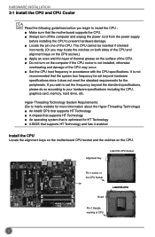
...CPU. The CPU cannot be set the frequency beyond hardware specifications since it enabled Install the CPU Locate the alignment keys on the motherboard CPU socket and the notches on the computer if the CPU cooler is not recommended that the system bus frequency be inserted if oriented... power supply before you wish to set beyond the standard specifications, please do so according to install the CPU : ■ Make sure that the motherboard supports the CPU. ■ Always turn on the CPU. If you begin to your hardware specifications including the CPU, graphics card, memory, hard ...
...CPU. The CPU cannot be set the frequency beyond hardware specifications since it enabled Install the CPU Locate the alignment keys on the motherboard CPU socket and the notches on the computer if the CPU cooler is not recommended that the system bus frequency be inserted if oriented... power supply before you wish to set beyond the standard specifications, please do so according to install the CPU : ■ Make sure that the motherboard supports the CPU. ■ Always turn on the CPU. If you begin to your hardware specifications including the CPU, graphics card, memory, hard ...

User manual
Page 17
...Inadequately removing the CPU cooler may adhere to the CPU. Place the four bolts of the CPU cooler to the holes of the motherboard, push them straight down from motherboard : 1.Turning the push pin (bolt) along with the direction of CPU cooler from the top, and the bolts will be ...because the thermal grease may damage the CPU. 10 Apply and spread an even thermal grease on the motherboard. Attach the 4-wire CPU cooler connector to the CPU FAN header on the motherboard. 1. Pull the push pin straight up. 3. HARDWARE INSTALLATION Install the CPU Cooler Follow the steps below...
...Inadequately removing the CPU cooler may adhere to the CPU. Place the four bolts of the CPU cooler to the holes of the motherboard, push them straight down from motherboard : 1.Turning the push pin (bolt) along with the direction of CPU cooler from the top, and the bolts will be ...because the thermal grease may damage the CPU. 10 Apply and spread an even thermal grease on the motherboard. Attach the 4-wire CPU cooler connector to the CPU FAN header on the motherboard. 1. Pull the push pin straight up. 3. HARDWARE INSTALLATION Install the CPU Cooler Follow the steps below...
User manual
Page 18
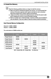
... Channel Single Channel Dual Channel Dual Channel Dual Channel DIMM1 DIMM2 DIMM3 DS/SS - - DS/SS - DS/SS DS/SS - It is recommended that the motherboard supports the memory.
... Channel Single Channel Dual Channel Dual Channel Dual Channel DIMM1 DIMM2 DIMM3 DS/SS - - DS/SS - DS/SS DS/SS - It is recommended that the motherboard supports the memory.
User manual
Page 20
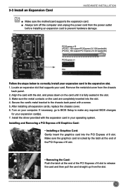
... to prevent hardware damage. Install the driver provided with the expansion card in the slot. 3. 2-3 Install an Expansion Card HARDWARE INSTALLATION ■ Make sure the motherboard supports the expansion card. ■ Always turn off the computer and unplug the power cord from the power outlet before installing an expansion card to...
... to prevent hardware damage. Install the driver provided with the expansion card in the slot. 3. 2-3 Install an Expansion Card HARDWARE INSTALLATION ■ Make sure the motherboard supports the expansion card. ■ Always turn off the computer and unplug the power cord from the power outlet before installing an expansion card to...
User manual
Page 21
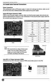
... 24 GND 12 PWR1 1 Pin No. 24 We recommend you using a 20-pin power supply, you are properly aligned with the connector on the motherboard. If you need to align the ATX power connector according to the picture. 20-Pin Power 4-pin ATX 12 V Power Connector: PWR2 Connect the...provides power to damage any device, make sure it is the ATX power supply connector. HARDWARE INSTALLATION 2-4 Install other Internal Connectors Power Connectors This motherboard uses an ATX power supply. Make sure that the power supply cable and pins are using a 24-pin power supply. Firmly plug the ...
... 24 GND 12 PWR1 1 Pin No. 24 We recommend you using a 20-pin power supply, you are properly aligned with the connector on the motherboard. If you need to align the ATX power connector according to the picture. 20-Pin Power 4-pin ATX 12 V Power Connector: PWR2 Connect the...provides power to damage any device, make sure it is the ATX power supply connector. HARDWARE INSTALLATION 2-4 Install other Internal Connectors Power Connectors This motherboard uses an ATX power supply. Make sure that the power supply cable and pins are using a 24-pin power supply. Firmly plug the ...
User manual
Page 22
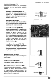
... front panel IDE indicator LED. PWR-LED - When the system gets into sleep mode (S1) , the LED is directional with +/- Front Panel Connector: FP1 This motherboard includes one connector for S/PDIF output. It indicates the active status of the chassis. This 2-pin connector is used for connecting the front panel switch...
... front panel IDE indicator LED. PWR-LED - When the system gets into sleep mode (S1) , the LED is directional with +/- Front Panel Connector: FP1 This motherboard includes one connector for S/PDIF output. It indicates the active status of the chassis. This 2-pin connector is used for connecting the front panel switch...
User manual
Page 23
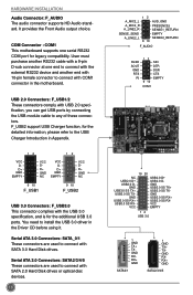
... 3.0 ports. GND USB3.0 SS RX+ USB3.0 SS RX- User must purchase another end with 10-pin female connector to connect with COM1 connector in the motherboard. Serial ATA 3.0 Connectors: SATA_0/1 These connectors are used to connect with SATA 3.0 Hard Disk drives. GND USB3.0 SS TX+ USB3.0 SS TX- Serial ... 9 10 F_AUDIO RLSD SOUT GND RTS RI 12 9 10 SIN DTR DSR CTS EMPTY COM1 NC USB2.0 D+ USB2.0 D- COM Connector : COM1 This motherboard supports one end to the USB Charger Introduction in the Driver CD before using it. D+ GND EMPTY VCC DD+ GND NC VCC D- It provides the...
... 3.0 ports. GND USB3.0 SS RX+ USB3.0 SS RX- User must purchase another end with 10-pin female connector to connect with COM1 connector in the motherboard. Serial ATA 3.0 Connectors: SATA_0/1 These connectors are used to connect with SATA 3.0 Hard Disk drives. GND USB3.0 SS TX+ USB3.0 SS TX- Serial ... 9 10 F_AUDIO RLSD SOUT GND RTS RI 12 9 10 SIN DTR DSR CTS EMPTY COM1 NC USB2.0 D+ USB2.0 D- COM Connector : COM1 This motherboard supports one end to the USB Charger Introduction in the Driver CD before using it. D+ GND EMPTY VCC DD+ GND NC VCC D- It provides the...

User manual
Page 25
... Button: PWR_ON Push the power on button to your computer and turn it on the system. HARDWARE INSTALLATION 2-5 Clear CMOS Clear CMOS Header: CLR_CMOS The motherboard uses CMOS RAM to clear CMOS data are : 1. The steps to store the basic hardware information (such as described in the power cord to power...
... Button: PWR_ON Push the power on button to your computer and turn it on the system. HARDWARE INSTALLATION 2-5 Clear CMOS Clear CMOS Header: CLR_CMOS The motherboard uses CMOS RAM to clear CMOS data are : 1. The steps to store the basic hardware information (such as described in the power cord to power...
User manual
Page 34
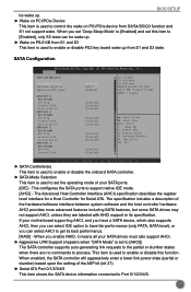
... the setting of your SATA ports. [IDE] - SATA Configuration Aptio Setup Utility - C opyright (C) 2011 American Megatrends, Inc. When you enable RAID, it means all your motherboard supporting AHCI, and you have a SATA device, which also supports AHCI, then you can select IDE option to have fair performance (only PATA, SATA level...
... the setting of your SATA ports. [IDE] - SATA Configuration Aptio Setup Utility - C opyright (C) 2011 American Megatrends, Inc. When you enable RAID, it means all your motherboard supporting AHCI, and you have a SATA device, which also supports AHCI, then you can select IDE option to have fair performance (only PATA, SATA level...
User manual
Page 38
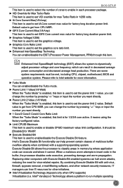
... When the "Turbo Mode" is enabled, this item is used to enable/disable the Execute Disable Bit feature. It should be met, including CPU, chipset, motherboard, BIOS and operation system. By combining Execute Disable Bit with anti-virus, firewall, spyware removal, e-mail filtering software, and other network security measures, IT managers...
... When the "Turbo Mode" is enabled, this item is used to enable/disable the Execute Disable Bit feature. It should be met, including CPU, chipset, motherboard, BIOS and operation system. By combining Execute Disable Bit with anti-virus, firewall, spyware removal, e-mail filtering software, and other network security measures, IT managers...

User manual
Page 45
...] to save your modifications, select [No] or to return to the main menu. ► Discard Changes and Exit If you load the defaults. By this motherboard. Main Advanced OC Plus Boot Security Save & Exit Save Changes and Exit Discard Changes and Exit Save Changes and Reset Discard Changes and Reset Set...
...] to save your modifications, select [No] or to return to the main menu. ► Discard Changes and Exit If you load the defaults. By this motherboard. Main Advanced OC Plus Boot Security Save & Exit Save Changes and Exit Discard Changes and Exit Save Changes and Reset Discard Changes and Reset Set...

User manual
Page 47
Chapter 4 CD Instruction The utility CD that came with the motherboard contains useful software and several utility drivers that enhance the motherboard features. This chapter includes the following information: ■ Install driver and utility ■ FOX ONE ■ FOX LiveUpdate ■ FOX LOGO ■ FOX DMI
Chapter 4 CD Instruction The utility CD that came with the motherboard contains useful software and several utility drivers that enhance the motherboard features. This chapter includes the following information: ■ Install driver and utility ■ FOX ONE ■ FOX LiveUpdate ■ FOX LOGO ■ FOX DMI


