English Manual.
Page 10
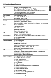
...*: Overclocking) Audio Realtek ALC888 chip High Definition Audio 2/4/5.1/7.1-channel Support for S/PDIF out Support Jack-Sensin function LAN On board Realtek 8111B chip Support 10/100/1000 Mb/s Ethernet Expansion Slots 2 x PCI Express x16 slots(1 x PCI-E x16 mode, 1 x PCI-E x4 mode) 2 x PCI Express x1 slots 3 x PCI slots Onboard Serial ATA 6 x SATA connectors 1 x External SATA connector 300MB/s data transfer rate Support hot plug and NCQ (Native Command Queuing ) Support RAID 0, RAID 1, RAID 5, RAID 10 Support Intel® Matrix Storage Technology USB Support hot...
...*: Overclocking) Audio Realtek ALC888 chip High Definition Audio 2/4/5.1/7.1-channel Support for S/PDIF out Support Jack-Sensin function LAN On board Realtek 8111B chip Support 10/100/1000 Mb/s Ethernet Expansion Slots 2 x PCI Express x16 slots(1 x PCI-E x16 mode, 1 x PCI-E x4 mode) 2 x PCI Express x1 slots 3 x PCI slots Onboard Serial ATA 6 x SATA connectors 1 x External SATA connector 300MB/s data transfer rate Support hot plug and NCQ (Native Command Queuing ) Support RAID 0, RAID 1, RAID 5, RAID 10 Support Intel® Matrix Storage Technology USB Support hot...
English Manual.
Page 15
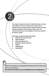
... Memory ■ Install an Expansion Card ■ Install other internal Connectors ■ Jumpers ■ Onboard Button ■ Onboard LED Please visit this chapter carefully. Please refer to the motherboard layout prior to any installation and read the contents in this website for more supporting information about CPU, Memory and VGA for your motherboard : http://www.foxconnchannel.com/product/Motherboards/compatibility.aspx This chapter introduces the hardware installation process, including the installation of the CPU, memory, power supply, slots, pin headers...
... Memory ■ Install an Expansion Card ■ Install other internal Connectors ■ Jumpers ■ Onboard Button ■ Onboard LED Please visit this chapter carefully. Please refer to the motherboard layout prior to any installation and read the contents in this website for more supporting information about CPU, Memory and VGA for your motherboard : http://www.foxconnchannel.com/product/Motherboards/compatibility.aspx This chapter introduces the hardware installation process, including the installation of the CPU, memory, power supply, slots, pin headers...
English Manual.
Page 21
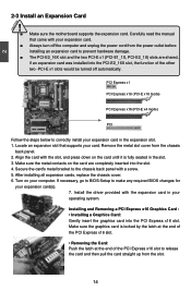
..., if an expansion card was installed into the PCI-E2_16X slot, the function of the PCI Express x16 slot to the chassis back panel with your expansion card(s). 7. After installing all expansion cards, replace the chassis cover. 6. Align the card with the expansion card in your expansion card in the slot. 3. Installing and Removing a PCI Express x16 Graphics Card : • Installing a Graphics Card: Gently insert the graphics card into the slot. 4. 2 CAUTION 2-3 Install an Expansion Card ! ■ Make sure the motherboard supports the expansion card.
..., if an expansion card was installed into the PCI-E2_16X slot, the function of the PCI Express x16 slot to the chassis back panel with your expansion card(s). 7. After installing all expansion cards, replace the chassis cover. 6. Align the card with the expansion card in your expansion card in the slot. 3. Installing and Removing a PCI Express x16 Graphics Card : • Installing a Graphics Card: Gently insert the graphics card into the slot. 4. 2 CAUTION 2-3 Install an Expansion Card ! ■ Make sure the motherboard supports the expansion card.
English Manual.
Page 24
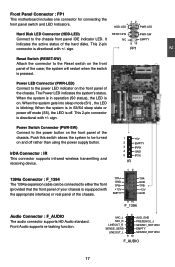
... This motherboard includes one connector for connecting the front panel switch and LED Indicators. Hard Disk LED Connector (HDD-LED) Connect to the power button on the front panel of the hard disks. sign. the system will restart when the switch is blinking; Power LED Connector (PWR-LED) Connect to either the front (provided that the front panel of the chassis. When the system gets into sleep mode (S1) , the LED is pressed. This 2-pin connector is off rather than using the power supply button. Power Switch Connector...
... This motherboard includes one connector for connecting the front panel switch and LED Indicators. Hard Disk LED Connector (HDD-LED) Connect to the power button on the front panel of the hard disks. sign. the system will restart when the switch is blinking; Power LED Connector (PWR-LED) Connect to either the front (provided that the front panel of the chassis. When the system gets into sleep mode (S1) , the LED is pressed. This 2-pin connector is off rather than using the power supply button. Power Switch Connector...

English Manual.
Page 26
... Jumpers 1. For any jumper setting. Go to BIOS Setup to configure new system as BIOS data, date, time information, hardware password...etc.). Description of this motherboard by a screwdriver for a few seconds, but using jumper cap is recommended. Plug in the power cord to clear CMOS data are : 1. The steps to your computer and turn it onto pins 1 and 2 to short them. Turn off the computer, unplug the power cord from pins...
... Jumpers 1. For any jumper setting. Go to BIOS Setup to configure new system as BIOS data, date, time information, hardware password...etc.). Description of this motherboard by a screwdriver for a few seconds, but using jumper cap is recommended. Plug in the power cord to clear CMOS data are : 1. The steps to your computer and turn it onto pins 1 and 2 to short them. Turn off the computer, unplug the power cord from pins...

English Manual.
Page 30
... set up through this menu. ► Set User Password The user password can be set up through this menu. ► Load Fail-Safe Defaults The Fail-safe default BIOS settings can be loaded through this menu. ► Save & Exit Setup Save setting values to CMOS and exit. ► Exit Without Saving Do not change Fan speeds, and displays temperatures and voltages of using this default. ► Load Optimized Defaults The optimal performance settings can be loaded through this manual, they are not the combination keys...
... set up through this menu. ► Set User Password The user password can be set up through this menu. ► Load Fail-Safe Defaults The Fail-safe default BIOS settings can be loaded through this menu. ► Save & Exit Setup Save setting values to CMOS and exit. ► Exit Without Saving Do not change Fan speeds, and displays temperatures and voltages of using this default. ► Load Optimized Defaults The optimal performance settings can be loaded through this manual, they are not the combination keys...
English Manual.
Page 31
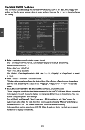
Video EGA/VGA Halt On All Errors BIOS ID P35A04.F1.P.09.MARS ▲ Item Help █ █ Menu Level Press [Enter] to enter █ next page for legacy compatibility. 24 You can auto-detect the hard disk when booting up the standard BIOS features, such as the date, time, floppy drive and so on. to select a field. Year-year, set up /down keys to select an item, then use , , or...
Video EGA/VGA Halt On All Errors BIOS ID P35A04.F1.P.09.MARS ▲ Item Help █ █ Menu Level Press [Enter] to enter █ next page for legacy compatibility. 24 You can auto-detect the hard disk when booting up the standard BIOS features, such as the date, time, floppy drive and so on. to select a field. Year-year, set up /down keys to select an item, then use , , or...

English Manual.
Page 33
... CMOS Setup Utility Advanced BIOS Features ► Hard Disk Boot Priority Virus Warning First Boot Device Second Boot Device Third Boot Device Boot Other Device Boot Up Floppy Seek Boot Up NumLock Status Gate A20 Option Typematic Rate Setting x Typematic Rate (Chars/Sec) x Typematic Delay (Msec) Security Option APIC Mode MPS Version Control for OS OS Select For DRAM > 64MB Report No FDD For WIN 95 Full Screen Logo Show Small Logo(EPA) Show Press Enter Disabled Hard Disk CDROM USB-ZIP Enabled Disabled...
... CMOS Setup Utility Advanced BIOS Features ► Hard Disk Boot Priority Virus Warning First Boot Device Second Boot Device Third Boot Device Boot Other Device Boot Up Floppy Seek Boot Up NumLock Status Gate A20 Option Typematic Rate Setting x Typematic Rate (Chars/Sec) x Typematic Delay (Msec) Security Option APIC Mode MPS Version Control for OS OS Select For DRAM > 64MB Report No FDD For WIN 95 Full Screen Logo Show Small Logo(EPA) Show Press Enter Disabled Hard Disk CDROM USB-ZIP Enabled Disabled...

English Manual.
Page 34
... 1.4 introduces support for enabling new features in a specific machine. APIC interrupt subsystems can contribute to enter the CMOS Setup screen; MPS 1.1 was the original specification. When it specifies the version of the MPS that doesn't come with two or more that 64MB of the secondary PCI bus on a motherboard that the motherboard will use of memory and you are required in the PCI specification. ► MPS Version Control For...
... 1.4 introduces support for enabling new features in a specific machine. APIC interrupt subsystems can contribute to enter the CMOS Setup screen; MPS 1.1 was the original specification. When it specifies the version of the MPS that doesn't come with two or more that 64MB of the secondary PCI bus on a motherboard that the motherboard will use of memory and you are required in the PCI specification. ► MPS Version Control For...

English Manual.
Page 36
... on the network. AwardBIOS CMOS Setup Utility Integrated Peripherals ► OnChip IDE Device ► Onboard Device Control ► USB Device Setting Onboard Lan Boot ROM Onboard FDC Controller Onboard Serial Port 1 Onboard IrDA Device UR2 Duplex Mode Press Enter Item Help Press Enter Press Enter Menu Level ► Disabled Enabled 3F8/IRQ4 2F8/IRQ3 Half Move Enter:Select +/-/PU/PD:Value F10:Save ESC:Exit F1:General Help F5:Previous Values F6:Fail-Safe Defaults F7:Optimized Defaults ► OnChip IDE Device/Onboard Device Control /USB Device Setting Press to...
... on the network. AwardBIOS CMOS Setup Utility Integrated Peripherals ► OnChip IDE Device ► Onboard Device Control ► USB Device Setting Onboard Lan Boot ROM Onboard FDC Controller Onboard Serial Port 1 Onboard IrDA Device UR2 Duplex Mode Press Enter Item Help Press Enter Press Enter Menu Level ► Disabled Enabled 3F8/IRQ4 2F8/IRQ3 Half Move Enter:Select +/-/PU/PD:Value F10:Save ESC:Exit F1:General Help F5:Previous Values F6:Fail-Safe Defaults F7:Optimized Defaults ► OnChip IDE Device/Onboard Device Control /USB Device Setting Press to...

English Manual.
Page 37
... Memory (Robson Technology) features an integrated disk cache using JMicron chip to speed up disk access and also save energy. This item is used to set your system with old fashion type IDE devices which run slowly. 30 It uses non-volatile memory (Flash memory) to use your PATA and e-SATA to IDE mode or RAID Mode or AHCI+IDE mode(AHCI for e-SATA, IDE for HDD while booting. AwardBIOS CMOS Setup Utility OnChip IDE Device SATA Mode LEGACY Mode Support x Turbo Memory Support Onboard IDE/SATA Chip Delay For HDD (Secs) IDE Item Help Disabled Disabled Menu Level ► IDE...
... Memory (Robson Technology) features an integrated disk cache using JMicron chip to speed up disk access and also save energy. This item is used to set your system with old fashion type IDE devices which run slowly. 30 It uses non-volatile memory (Flash memory) to use your PATA and e-SATA to IDE mode or RAID Mode or AHCI+IDE mode(AHCI for e-SATA, IDE for HDD while booting. AwardBIOS CMOS Setup Utility OnChip IDE Device SATA Mode LEGACY Mode Support x Turbo Memory Support Onboard IDE/SATA Chip Delay For HDD (Secs) IDE Item Help Disabled Disabled Menu Level ► IDE...
English Manual.
Page 39
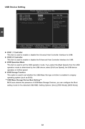
Setting Options: [Auto]; [FDD Mode]; [HDD Mode]. 32 3 USB Device Setting Phoenix - AwardBIOS CMOS Setup Utility USB Device Setting USB 1.1 Controller Enabled Item Help USB 2.0 Controller Enabled USB Operation Mode High Speed Menu Level ► USB Storage Function Enabled [Enable] or [Disable] *** USB Mass Storage Device Boot Setting *** Universal Host Controller Interface for Universal Serial Bus Move Enter:Select +/-/PU/PD:Value F10:Save ESC:Exit F1:General Help F5:Previous Values F6:Fail-Safe Defaults F7:Optimized Defaults...
Setting Options: [Auto]; [FDD Mode]; [HDD Mode]. 32 3 USB Device Setting Phoenix - AwardBIOS CMOS Setup Utility USB Device Setting USB 1.1 Controller Enabled Item Help USB 2.0 Controller Enabled USB Operation Mode High Speed Menu Level ► USB Storage Function Enabled [Enable] or [Disable] *** USB Mass Storage Device Boot Setting *** Universal Host Controller Interface for Universal Serial Bus Move Enter:Select +/-/PU/PD:Value F10:Save ESC:Exit F1:General Help F5:Previous Values F6:Fail-Safe Defaults F7:Optimized Defaults...

English Manual.
Page 46
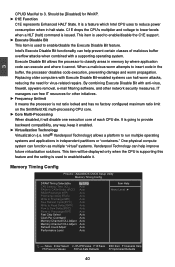
AwardBIOS CMOS Setup Utility CPU Feature EIST Function Limit CPUID MaxVal C1E Function Execute Disable Bit Frequency Unlimit Core Multi-Processing Virtualization Technology Native Mode Disabled Auto Enabled Disabled Enabled Enabled Item Help CAUTION Move Enter:Select +/-/PU/PD:Value F10:Save ESC:Exit F1:General Help F5:Previous Values F6:Fail-Safe Defaults F7:Optimized Defaults ! Enhanced Intel SpeedStep® technology (EIST) allows the system to comply with PCI Express bus clock); [33.6 MHz]; [37.3 MHz...
AwardBIOS CMOS Setup Utility CPU Feature EIST Function Limit CPUID MaxVal C1E Function Execute Disable Bit Frequency Unlimit Core Multi-Processing Virtualization Technology Native Mode Disabled Auto Enabled Disabled Enabled Enabled Item Help CAUTION Move Enter:Select +/-/PU/PD:Value F10:Save ESC:Exit F1:General Help F5:Previous Values F6:Fail-Safe Defaults F7:Optimized Defaults ! Enhanced Intel SpeedStep® technology (EIST) allows the system to comply with PCI Express bus clock); [33.6 MHz]; [37.3 MHz...
English Manual.
Page 47
...) Auto Read to enable/disable the Execute Disable Bit feature. C1E drops the CPU's multiplier and voltage to provide backward compatibility, any way, keep it enabled. ► Virtualization Technology Virtualization (i.e. Intel's Execute Disable Bit functionality can free IT resources for virus-related repairs. One physical compute system can function as multiple "virtual" systems. Vanderpool Technology can execute and where it cannot. Execute Disable Bit allows the processor to insert code in memory by...
...) Auto Read to enable/disable the Execute Disable Bit feature. C1E drops the CPU's multiplier and voltage to provide backward compatibility, any way, keep it enabled. ► Virtualization Technology Virtualization (i.e. Intel's Execute Disable Bit functionality can free IT resources for virus-related repairs. One physical compute system can function as multiple "virtual" systems. Vanderpool Technology can execute and where it cannot. Execute Disable Bit allows the processor to insert code in memory by...

English Manual.
Page 50
... store Smart Power LED Enabled your motherboard to one of BIOS configuration data. The LED is a feature built on your setting to Current Storage Gear successfully, then the Storage Gear will turn to Green color If you to Foxconn Function store your BIOS settings. AwardBIOS CMOS Setup Utility OC Gear OC Gear Item Help Current Storage Gear Not Use It x Storage My Setting Store Menu Level ► x Restore My Setting Restore x Clear My Setting Clear Choose storage section...
... store Smart Power LED Enabled your motherboard to one of BIOS configuration data. The LED is a feature built on your setting to Current Storage Gear successfully, then the Storage Gear will turn to Green color If you to Foxconn Function store your BIOS settings. AwardBIOS CMOS Setup Utility OC Gear OC Gear Item Help Current Storage Gear Not Use It x Storage My Setting Store Menu Level ► x Restore My Setting Restore x Clear My Setting Clear Choose storage section...

English Manual.
Page 53
... display the main menu on "Install Driver", then use these options to install Realtek 8111 LAN driver. Install Driver Click on the screen. 1. Realtek 8111 LAN driver Use it to restart your computer after finishing all the necessary drivers for your CD drive. You need to install Realtek Audio driver. Realtek Audio drivers Use it to install all the installations of drivers. JMicron Raid drivers Use it to install JMicron RAID driver. Intel chipset driver Use it to install Intel chipset driver. JMircon provides one Utility CD. 4 Utility CD introduction This motherboard...
... display the main menu on "Install Driver", then use these options to install Realtek 8111 LAN driver. Install Driver Click on the screen. 1. Realtek 8111 LAN driver Use it to restart your computer after finishing all the necessary drivers for your CD drive. You need to install Realtek Audio driver. Realtek Audio drivers Use it to install all the installations of drivers. JMicron Raid drivers Use it to install JMicron RAID driver. Intel chipset driver Use it to install Intel chipset driver. JMircon provides one Utility CD. 4 Utility CD introduction This motherboard...
English Manual.
Page 54
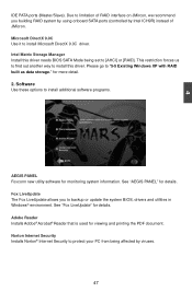
... another way to install this driver needs BIOS SATA Mode being affected by Intel ICH9R) instead of JMicron. See "AEGIS PANEL" for monitoring system information. Fox LiveUpdate The Fox LiveUpdate allows you building RAID system by using onboard SATA ports (controlled by viruses. 47 Microsoft DirectX 9.0C Use it to backup or update the system BIOS, drivers and utilities in Windows® environment. Software Use these options to [AHCI] or [RAID]. for details. See...
... another way to install this driver needs BIOS SATA Mode being affected by Intel ICH9R) instead of JMicron. See "AEGIS PANEL" for monitoring system information. Fox LiveUpdate The Fox LiveUpdate allows you building RAID system by using onboard SATA ports (controlled by viruses. 47 Microsoft DirectX 9.0C Use it to backup or update the system BIOS, drivers and utilities in Windows® environment. Software Use these options to [AHCI] or [RAID]. for details. See...

English Manual.
Page 76
... the "Main menu", then select the "OnChip IDE Device" item and press to go to enter the main menu of Intel® Matrix Storage Manager Option ROM Utility. AwardBIOS CMOS Setup Utility OnChip IDE Device SATA Mode LEGACY Mode Support x Robson Support Onboard IDE/SATA Chip Delay For HDD (Secs) RAID Item Help Disabled Disabled Menu Level ► IDE Mode 0 5 Move Enter:Select +/-/PU/PD:Value F10:Save ESC:Exit F1:General Help F5:Previous Values F6:Fail-Safe Defaults F7:Optimized Defaults 5-3 Create RAID in BIOS Enter RAID BIOS Setup When BIOS is...
... the "Main menu", then select the "OnChip IDE Device" item and press to go to enter the main menu of Intel® Matrix Storage Manager Option ROM Utility. AwardBIOS CMOS Setup Utility OnChip IDE Device SATA Mode LEGACY Mode Support x Robson Support Onboard IDE/SATA Chip Delay For HDD (Secs) RAID Item Help Disabled Disabled Menu Level ► IDE Mode 0 5 Move Enter:Select +/-/PU/PD:Value F10:Save ESC:Exit F1:General Help F5:Previous Values F6:Fail-Safe Defaults F7:Optimized Defaults 5-3 Create RAID in BIOS Enter RAID BIOS Setup When BIOS is...
English Manual.
Page 101
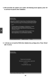
..., Setup will ask you floppy drive. Press after it is done. 5. After some files are copied to your system, the following mass storage device(s): * To specify additional SCSI adapters, CD-ROM drivers, or special disk controllers for use with Windows, including those for use with Windows, press ENTER. S=Specify Additional Device ENTER=Continue F3=Exit 6. Windows Setup Please insert the disk labeled manufacturer-supplied hardware support disk into you to specify additional mass storage devices...
..., Setup will ask you floppy drive. Press after it is done. 5. After some files are copied to your system, the following mass storage device(s): * To specify additional SCSI adapters, CD-ROM drivers, or special disk controllers for use with Windows, including those for use with Windows, press ENTER. S=Specify Additional Device ENTER=Continue F3=Exit 6. Windows Setup Please insert the disk labeled manufacturer-supplied hardware support disk into you to specify additional mass storage devices...

English Manual.
Page 105
...; Matrix Storage Manager option ROM utility). Configure your new hard disks to save and exit BIOS. Exit RAID BIOS. Phoenix - AwardBIOS CMOS Setup Utility OnChip IDE Device SATA Mode x LEGACY Mode Support x Turbo Memory Support Onboard IDE/SATA Chip Delay For HDD (Secs) RIDAEID Item Help Disabled Disabled Menu Level ► IDE Mode 0 Move Enter:Select +/-/PU/PD:Value F10:Save ESC:Exit F1:General Help F5:Previous Values F6:Fail-Safe Defaults F7:Optimized Defaults 3. Copy section 5-3, Create RAID in BIOS. Shut down the computer, connect SATA hard disks to...
...; Matrix Storage Manager option ROM utility). Configure your new hard disks to save and exit BIOS. Exit RAID BIOS. Phoenix - AwardBIOS CMOS Setup Utility OnChip IDE Device SATA Mode x LEGACY Mode Support x Turbo Memory Support Onboard IDE/SATA Chip Delay For HDD (Secs) RIDAEID Item Help Disabled Disabled Menu Level ► IDE Mode 0 Move Enter:Select +/-/PU/PD:Value F10:Save ESC:Exit F1:General Help F5:Previous Values F6:Fail-Safe Defaults F7:Optimized Defaults 3. Copy section 5-3, Create RAID in BIOS. Shut down the computer, connect SATA hard disks to...


