
Operation Manual
Page 3
..., Nagano, Japan Centronics is assumed with Seiko Epson Corporation's operating and maintenance instructions. Epson and ESC/POS are subject to the use of the information contained herein. No part of this publication may be reproduced, stored in a retrieval system, or transmitted in the preparation of this manual are registered trademarks of Centronics Data Computer Corporation. No patent liability is...
..., Nagano, Japan Centronics is assumed with Seiko Epson Corporation's operating and maintenance instructions. Epson and ESC/POS are subject to the use of the information contained herein. No part of this publication may be reproduced, stored in a retrieval system, or transmitted in the preparation of this manual are registered trademarks of Centronics Data Computer Corporation. No patent liability is...
Operation Manual
Page 4
...Standards Applied Printer Product Name: TM-U300C/D, TM-U300PC/PD Model Name: M51JC/D, M51PC/PD The following standards are applied only to the printers that are so labeled. (EMC is tested using the packaged AC adapter.) Europe...Control Law of Japan Oceania: Safety: AS 3260 WARNING The connection of a non-shielded printer interface cable to this printer will be required to cause harmful interference, in a commercial environment. This equipment generates, uses, and can radiate radio frequency energy and, if not installed and used in a residential area is operated in which case the user...
...Standards Applied Printer Product Name: TM-U300C/D, TM-U300PC/PD Model Name: M51JC/D, M51PC/PD The following standards are applied only to the printers that are so labeled. (EMC is tested using the packaged AC adapter.) Europe...Control Law of Japan Oceania: Safety: AS 3260 WARNING The connection of a non-shielded printer interface cable to this printer will be required to cause harmful interference, in a commercial environment. This equipment generates, uses, and can radiate radio frequency energy and, if not installed and used in a residential area is operated in which case the user...
Operation Manual
Page 5
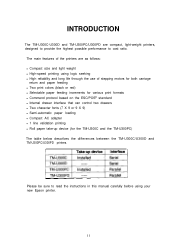
... instructions in this manual carefully before using logic seeking l High reliability and long life through the use of stepping motors for both carriage return and paper feeding l Two print colors (black or red) l Selectable paper feeding increments for various print formats l Command protocol based on the ESC/POS® standard l Internal drawer interface that can control two drawers l Two character fonts (7 X 9 or 9 X 9) l Semi-automatic paper loading l Compact AC adapter l 1 line validation printing l Roll paper...
... instructions in this manual carefully before using logic seeking l High reliability and long life through the use of stepping motors for both carriage return and paper feeding l Two print colors (black or red) l Selectable paper feeding increments for various print formats l Command protocol based on the ESC/POS® standard l Internal drawer interface that can control two drawers l Two character fonts (7 X 9 or 9 X 9) l Semi-automatic paper loading l Compact AC adapter l 1 line validation printing l Roll paper...
Operation Manual
Page 6
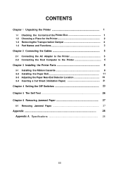
...a Place for the Printer 2 1-3 Removingthe Transportation Damper 2 1-4 Part Names and Functions 3 Chapter 2 Connecting the Cables 5 2-1 Connecting the AC Adapter to the Printer 5 2-2 Connecting the Host Computer to the Printer 6 Chapter 3 Installing the Printer Parts 8 3-1 Installing the Ribbon Cassette 8 3-2 Installing the Paper Roll 1 1 3-3 Adjusting the Paper Near-End Detector Location 19 3-4 Inserting a Cut Sheet (Validation Pape.r 21 Chapter 4 Setting the DIP Switches 23 Chapter 5 The Self Test 26 Chapter 6 Removing Jammed Paper 27 6-1 Removing Jammed Paper 27 Appendix ...28...
...a Place for the Printer 2 1-3 Removingthe Transportation Damper 2 1-4 Part Names and Functions 3 Chapter 2 Connecting the Cables 5 2-1 Connecting the AC Adapter to the Printer 5 2-2 Connecting the Host Computer to the Printer 6 Chapter 3 Installing the Printer Parts 8 3-1 Installing the Ribbon Cassette 8 3-2 Installing the Paper Roll 1 1 3-3 Adjusting the Paper Near-End Detector Location 19 3-4 Inserting a Cut Sheet (Validation Pape.r 21 Chapter 4 Setting the DIP Switches 23 Chapter 5 The Self Test 26 Chapter 6 Removing Jammed Paper 27 6-1 Removing Jammed Paper 27 Appendix ...28...
Operation Manual
Page 9
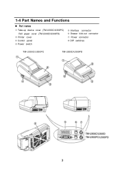
1-4 Part Names and Functions n Part names Œ Take-up device cover (TM-U300C/U300PC) Roll paper cover (TM-U300D/U300PD) Printer cover Ž Control panel Power switch Interface connector ‘ Drawer kick-out connector ’ Power connector “ DIP switches TM-U300C/U300PC TM-U300D/U300PD 3
1-4 Part Names and Functions n Part names Œ Take-up device cover (TM-U300C/U300PC) Roll paper cover (TM-U300D/U300PD) Printer cover Ž Control panel Power switch Interface connector ‘ Drawer kick-out connector ’ Power connector “ DIP switches TM-U300C/U300PC TM-U300D/U300PD 3
Operation Manual
Page 10
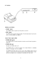
...; FEED Button The FEED button is used to feed roll paper. Control Panel Lights (LEDs) Ž POWER LED (green) The POWER LED is on when the printer is turned on when the paper roll is nearly finished or completely finished or the paper roll is not installed. The PAPER LED blinks when an error occurs, when validation paper must be inserted or removed, when the self test enters the printing standby state, or when printing has stopped...
...; FEED Button The FEED button is used to feed roll paper. Control Panel Lights (LEDs) Ž POWER LED (green) The POWER LED is on when the printer is turned on when the paper roll is nearly finished or completely finished or the paper roll is not installed. The PAPER LED blinks when an error occurs, when validation paper must be inserted or removed, when the self test enters the printing standby state, or when printing has stopped...
Operation Manual
Page 12
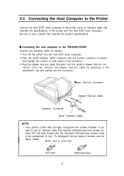
... connector's clip and pulling out the connector.) rawer Kick-out Connector Drawer Kick-out Cable Interface Connector Serial Interface Cable NOTE: l Your printer comes with the enclosed millimeter-type screws using an interface cable that matches the printer's specifications. Be sure to use a drawer that matches the specifications of the printer and the host ECR (host computer). place the inch-type screws with inch-type hexagonal lock screws installed.
... connector's clip and pulling out the connector.) rawer Kick-out Connector Drawer Kick-out Cable Interface Connector Serial Interface Cable NOTE: l Your printer comes with the enclosed millimeter-type screws using an interface cable that matches the printer's specifications. Be sure to use a drawer that matches the specifications of the printer and the host ECR (host computer). place the inch-type screws with inch-type hexagonal lock screws installed.
Operation Manual
Page 14
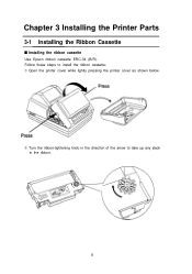
Chapter 3 Installing the Printer Parts 3-1 Installing the Ribbon Cassette s lnstalling the ribbon cassette Use Epson ribbon cassette ERC-34 (B/R). Follow these steps to install the ribbon cassette: ΠOpen the printer cover while lightly pressing the printer cover as shown below. Turn the ribbon-tightening knob in the direction of the arrow to take up any slack in the ribbon. 8
Chapter 3 Installing the Printer Parts 3-1 Installing the Ribbon Cassette s lnstalling the ribbon cassette Use Epson ribbon cassette ERC-34 (B/R). Follow these steps to install the ribbon cassette: ΠOpen the printer cover while lightly pressing the printer cover as shown below. Turn the ribbon-tightening knob in the direction of the arrow to take up any slack in the ribbon. 8

Operation Manual
Page 16
n Replacing the ribbon cassette Use Epson ribbon cassette ERC-34 (B/R). Œ Open the printer cover while lightly pressing the printer cover as shown below. To remove the ribbon cassette, grasp the tab on the left side and lift the left side out first. Ž To install a new ribbon cassette, follow steps through in the previous section, Installing the ribbon cassette. 1O
n Replacing the ribbon cassette Use Epson ribbon cassette ERC-34 (B/R). Œ Open the printer cover while lightly pressing the printer cover as shown below. To remove the ribbon cassette, grasp the tab on the left side and lift the left side out first. Ž To install a new ribbon cassette, follow steps through in the previous section, Installing the ribbon cassette. 1O
Operation Manual
Page 17
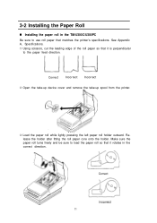
... lightly pressing the left paper roll holder outward. Correct 11 See Appendix A, Specifications. ΠUsing scissors, cut the leading edge of the roll paper so that it is perpendicular to use roll paper that matches the printer's specifications. Make sure the paper roll turns freely and be sure to load the paper roll so that it rotates in the TM-U300C/U300PC Be sure to the paper feed direction. 3-2 Installing the Paper...
... lightly pressing the left paper roll holder outward. Correct 11 See Appendix A, Specifications. ΠUsing scissors, cut the leading edge of the roll paper so that it is perpendicular to use roll paper that matches the printer's specifications. Make sure the paper roll turns freely and be sure to load the paper roll so that it rotates in the TM-U300C/U300PC Be sure to the paper feed direction. 3-2 Installing the Paper...

Operation Manual
Page 18
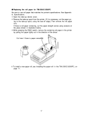
... POWER LED goes on the printer. The printer automatically feeds the roll paper into the paper inlet. Wrap the paper around the spool two or three times and then replace the side board of the roll paper straight into the printer (semi-automatic loading). ‘ Press the FEED button to continue feeding the paper until it extends about 20 cm (8 inches) beyond tear-off edge. ’ Remove the side board...
... POWER LED goes on the printer. The printer automatically feeds the roll paper into the paper inlet. Wrap the paper around the spool two or three times and then replace the side board of the roll paper straight into the printer (semi-automatic loading). ‘ Press the FEED button to continue feeding the paper until it extends about 20 cm (8 inches) beyond tear-off edge. ’ Remove the side board...
Operation Manual
Page 23
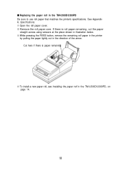
... paper remaining, cut the paper go- s Replacing the roll paper for TM-U300C/U300PC Be sure to the take -up spool, using scissors at the place shown in illustration below. Ž While pressing the FEED switch, remove the remaining roll paper in the printer by pulling the paper lightly out in the TM-U300C/U300PC, on page 11. 17 If there is paper remaini To install a new paper roll, see Installing...
... paper remaining, cut the paper go- s Replacing the roll paper for TM-U300C/U300PC Be sure to the take -up spool, using scissors at the place shown in illustration below. Ž While pressing the FEED switch, remove the remaining roll paper in the printer by pulling the paper lightly out in the TM-U300C/U300PC, on page 11. 17 If there is paper remaini To install a new paper roll, see Installing...
Operation Manual
Page 24
... Appendix A, Specifications. Œ Open the roll paper cover. Remove the roll paper core. s Replacing the paper roll in the direction of the arrow. Cut here if there is roll paper remaining, cut the paper straight across using scissors at the place shown in illustration below. Ž While pressing the FEED button, remove the remaining roll paper in the printer by pulling the paper lightly out in the TM-U300D/U300PD...
... Appendix A, Specifications. Œ Open the roll paper cover. Remove the roll paper core. s Replacing the paper roll in the direction of the arrow. Cut here if there is roll paper remaining, cut the paper straight across using scissors at the place shown in illustration below. Ž While pressing the FEED button, remove the remaining roll paper in the printer by pulling the paper lightly out in the TM-U300D/U300PD...
Operation Manual
Page 26
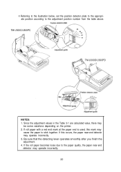
... the paper end is used, this occurs, the paper near -end detector may be some variations depending on the printer. 2. Be sure that the detecting lever operates smoothly after you finish the adjustment. 4. If this mark may operate incorrectly. 3. Referring to the illustration below, set the position detector plate to the appropriate position according to stick together. TM-U300C/U300PC TM-U300D...
... the paper end is used, this occurs, the paper near -end detector may be some variations depending on the printer. 2. Be sure that the detecting lever operates smoothly after you finish the adjustment. 4. If this mark may operate incorrectly. 3. Referring to the illustration below, set the position detector plate to the appropriate position according to stick together. TM-U300C/U300PC TM-U300D...
Operation Manual
Page 27
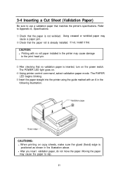
... the paper may cause a paper jam. Check that matches the printer's specifications. CAUTIONS: l When printing on copy sheets, make sure the glued (fixed) edge is not wrinkled. If not, install it first. Using creased or wrinkled paper may cause the paper to slip. 21 The POWER LED light goes on. Using printer control command, select validation paper mode. 3-4 Inserting a Cut Sheet (Validation Paper) Be sure to use a validation paper that the paper roll is inserted, turn on the power switch.
... the paper may cause a paper jam. Check that matches the printer's specifications. CAUTIONS: l When printing on copy sheets, make sure the glued (fixed) edge is not wrinkled. If not, install it first. Using creased or wrinkled paper may cause the paper to slip. 21 The POWER LED light goes on. Using printer control command, select validation paper mode. 3-4 Inserting a Cut Sheet (Validation Paper) Be sure to use a validation paper that the paper roll is inserted, turn on the power switch.

Operation Manual
Page 28
l Select multi-ply paper carefully because the gluing conditions (glue quality, gluing method, glued length etc.) and the position of the paper as shown in the area shown below or the paper detector does not work correctly. Validation paper 22 However, printing is affected by the print commands, but the paper is not fed. l The validation paper should be flat, with holes (e.g., sprocket holes) in...
l Select multi-ply paper carefully because the gluing conditions (glue quality, gluing method, glued length etc.) and the position of the paper as shown in the area shown below or the paper detector does not work correctly. Validation paper 22 However, printing is affected by the print commands, but the paper is not fed. l The validation paper should be flat, with holes (e.g., sprocket holes) in...
Operation Manual
Page 29
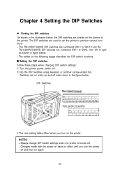
Switches are numbered SW-1 to SW-8, from left to SW-10 and the TM-U300PC/U300PD DIP switches are on when up and off and then on the printer. s Setting the DIP switches Follow these steps when changing DIP switch settings: ΠTurn the printer power switch off . NOTES: l Always change DIP switch settings when the printer is turned off . Flip the DIP switches using tweezers or another narrow-ended tool. l Changes made with the power on have no...
Switches are numbered SW-1 to SW-8, from left to SW-10 and the TM-U300PC/U300PD DIP switches are on when up and off and then on the printer. s Setting the DIP switches Follow these steps when changing DIP switch settings: ΠTurn the printer power switch off . NOTES: l Always change DIP switch settings when the printer is turned off . Flip the DIP switches using tweezers or another narrow-ended tool. l Changes made with the power on have no...
Operation Manual
Page 32
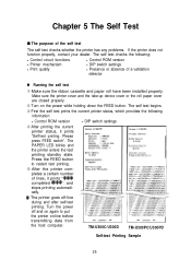
... the test printing standby state. l DIP switch settings TM-U300C/U300D TM-U300PC/U300PD Self-test Printing Sample 26 The self test checks the following information: l Control ROM version After printing the current printer status, it prints " * * * completed * * * ", and stops printing automatically. * The printer goes off and on again to restart test printing. After the printer completes a certain number of lines, it prints "Self-test printing. Please press FEED switch". Press the FEED button to put the printer on the power while holding down the FEED button. Make...
... the test printing standby state. l DIP switch settings TM-U300C/U300D TM-U300PC/U300PD Self-test Printing Sample 26 The self test checks the following information: l Control ROM version After printing the current printer status, it prints " * * * completed * * * ", and stops printing automatically. * The printer goes off and on again to restart test printing. After the printer completes a certain number of lines, it prints "Self-test printing. Please press FEED switch". Press the FEED button to put the printer on the power while holding down the FEED button. Make...
Operation Manual
Page 34
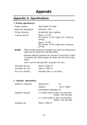
...) (CPI: Characters Per Inch) Characters per line: Characters per second: Serial impact dot matrix Serial-type, 9-pin Bi-directional (logic seeking) Approx. 3.5 LPS (40 columns, 16 CPI, single color, continuous printing) Approx. 5.8 LPS (20 columns, 16 CPI, single color, continuous printing) NOTES: l When printing exceeds the allowable duty cycle, the actual printing speed may be slower than that listed above. Refer to Table A-1. Character Specifications Number of characters: Character structure: Character size: Alphanumeric: 95 Graphics: 128 X 7 tables International characters...
...) (CPI: Characters Per Inch) Characters per line: Characters per second: Serial impact dot matrix Serial-type, 9-pin Bi-directional (logic seeking) Approx. 3.5 LPS (40 columns, 16 CPI, single color, continuous printing) Approx. 5.8 LPS (20 columns, 16 CPI, single color, continuous printing) NOTES: l When printing exceeds the allowable duty cycle, the actual printing speed may be slower than that listed above. Refer to Table A-1. Character Specifications Number of characters: Character structure: Character size: Alphanumeric: 95 Graphics: 128 X 7 tables International characters...
Operation Manual
Page 36
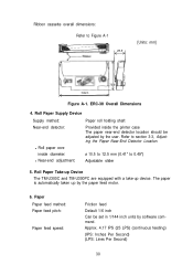
... be set in 1/144 inch units by software command. Paper Paper feed method: Paper feed pitch: Paper feed speed: Friction feed Default 1/6 inch Can be adjusted by the paper feed motor. 6. The paper is automatically taken up device. Roll Paper Take-up Device The TM-U300C and TM-U300PC are equipped with a take-up by the user. Approx. 4.17 IPS (25 LPS) (continuous feeding) (IPS: Inches Per Second) (LPS: Lines Per Second) 30 Refer to section 3-3, Adjusting the Paper Near...
... be set in 1/144 inch units by software command. Paper Paper feed method: Paper feed pitch: Paper feed speed: Friction feed Default 1/6 inch Can be adjusted by the paper feed motor. 6. The paper is automatically taken up device. Roll Paper Take-up Device The TM-U300C and TM-U300PC are equipped with a take-up by the user. Approx. 4.17 IPS (25 LPS) (continuous feeding) (IPS: Inches Per Second) (LPS: Lines Per Second) 30 Refer to section 3-3, Adjusting the Paper Near...


