
Operation Manual
Page 5
... 33 Fig. 46 Gap Adjustment 35 Fig. 47 Switches and Indicators on Control Panel 36 Fig. 48 Printer Initial Check 38 Fig. 49 Flowchart of Paper Out Status Release Procedure 39 Fig. 50 Removing Manual Paper Feed Knob 41 Fig. 51 Loosening All 4 Screws 41 Fig. 52 Pulling Out Wires Hooked to... Control Panel 42 Fig. 53 Construction of Type II Printer 43 Fig. 54 Location of DIP Switches 4 4 Fig. 55 Setting DIP Switches...
... 33 Fig. 46 Gap Adjustment 35 Fig. 47 Switches and Indicators on Control Panel 36 Fig. 48 Printer Initial Check 38 Fig. 49 Flowchart of Paper Out Status Release Procedure 39 Fig. 50 Removing Manual Paper Feed Knob 41 Fig. 51 Loosening All 4 Screws 41 Fig. 52 Pulling Out Wires Hooked to... Control Panel 42 Fig. 53 Construction of Type II Printer 43 Fig. 54 Location of DIP Switches 4 4 Fig. 55 Setting DIP Switches...
Operation Manual
Page 7
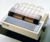
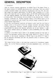
... A one-chip microcomputer performs all system control and the two built-in stepper motors of EPSON advanced printer technology. In this manual, installation of MX-80 Type II and MX-80 F/T Type II will be described. *Bit Image printing refers to both will be described ...-over perforation are available to the MX-80 Type II which is the latest extension of the printer control the carriage movement and paper feeding functions respectively. Fig. 1 EPSON MX-80 Type I I and MX-80 F/T Type I I Dot Matrix Printers -1- This new printer couples innovative design and precision manufacturing with...
... A one-chip microcomputer performs all system control and the two built-in stepper motors of EPSON advanced printer technology. In this manual, installation of MX-80 Type II and MX-80 F/T Type II will be described. *Bit Image printing refers to both will be described ...-over perforation are available to the MX-80 Type II which is the latest extension of the printer control the carriage movement and paper feeding functions respectively. Fig. 1 EPSON MX-80 Type I I and MX-80 F/T Type I I Dot Matrix Printers -1- This new printer couples innovative design and precision manufacturing with...
Operation Manual
Page 10
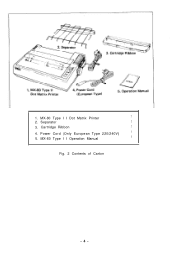
Separator 1 3. MX-80 Type I I Dot Matrix Printer 1 2. Cartridge Ribbon 1 4. Power Cord (Only European Type 220/240V) 1 5. MX-80 Type I I Operation Manual 1 Fig. 2 Contents of Carton -4- 1.
Separator 1 3. MX-80 Type I I Dot Matrix Printer 1 2. Cartridge Ribbon 1 4. Power Cord (Only European Type 220/240V) 1 5. MX-80 Type I I Operation Manual 1 Fig. 2 Contents of Carton -4- 1.
Operation Manual
Page 20
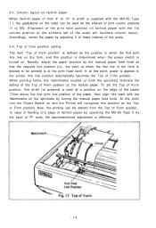
... the Top of print column positions (1 to the printer, this mark with the matchmarks on fanfold paper with the MX-80 Type I I, the graduations on the fanfold paper. In case of feeding one page of fanfold paper by operating the MX-80 Type II by turning the manual paper feed knob. Column layout on fanfold paper...
... the Top of print column positions (1 to the printer, this mark with the matchmarks on fanfold paper with the MX-80 Type I I, the graduations on the fanfold paper. In case of feeding one page of fanfold paper by operating the MX-80 Type II by turning the manual paper feed knob. Column layout on fanfold paper...

Operation Manual
Page 24
.... Your layout may cause the malfunction of Carton 3. Separator 1 3. Cartridge Ribbon 1 4. MX-80 F/T Type I I , observe the following instructions. (a) Place the Printer on which the MX-80 F/T Type I I is placed. (b) Avoid operating the MX-80 F/T Type. Installation of the Printer (1) Operating site selection When installing the MX-80 F/T Type I I Operation Manual 1 Fig. 19 Contents of the print head. (c) Connect the power cord...
.... Your layout may cause the malfunction of Carton 3. Separator 1 3. Cartridge Ribbon 1 4. MX-80 F/T Type I I , observe the following instructions. (a) Place the Printer on which the MX-80 F/T Type I I is placed. (b) Avoid operating the MX-80 F/T Type. Installation of the Printer (1) Operating site selection When installing the MX-80 F/T Type I I Operation Manual 1 Fig. 19 Contents of the print head. (c) Connect the power cord...
Operation Manual
Page 34
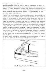
... of form position setting The term "Top of Form position" is defined as the position in width is supplied with the MX-80 F/T Type II, the graduations on the sprockets by the manual paper feed knob S O that the required line position (i.e., the point at which the first print line lies on the form...scale. 7.1.4. If, at a position on the edge of the paper 77mm above the first print line position of the print start position on and the Printer will facilitate column layout. To set the Top of Form position, first enter (or preprint) a mark at this point, power is at the extreme left...
... of form position setting The term "Top of Form position" is defined as the position in width is supplied with the MX-80 F/T Type II, the graduations on the sprockets by the manual paper feed knob S O that the required line position (i.e., the point at which the first print line lies on the form...scale. 7.1.4. If, at a position on the edge of the paper 77mm above the first print line position of the print start position on and the Printer will facilitate column layout. To set the Top of Form position, first enter (or preprint) a mark at this point, power is at the extreme left...
Operation Manual
Page 35
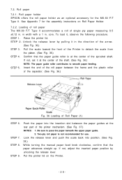
...the front of the Printer to pass the paper beneath the upper paper guide. 2. Insert the end of the roll paper between the paper guides at the center of Roll Paper (1) STEP 6. Push the paper into position. (See Fig. 38.) While turning the manual paper feed knob clockwise,...it at the rear part of the sprocket shaft. See Appendix 7 for the MX-80 F/T Type II. STEP 5. STEP 9. Roll paper holder EPSON offers the roll paper holder as an optional accessory for the assembly instructions on the Printer. -29- Confirm that the paper advances straight up. Two-ply roll paper...
...the front of the Printer to pass the paper beneath the upper paper guide. 2. Insert the end of the roll paper between the paper guides at the center of Roll Paper (1) STEP 6. Push the paper into position. (See Fig. 38.) While turning the manual paper feed knob clockwise,...it at the rear part of the sprocket shaft. See Appendix 7 for the MX-80 F/T Type II. STEP 5. STEP 9. Roll paper holder EPSON offers the roll paper holder as an optional accessory for the assembly instructions on the Printer. -29- Confirm that the paper advances straight up. Two-ply roll paper...

Operation Manual
Page 37
STEP 6. While turning the manual paper feed knob clockwise, confirm that the paper advances straight up. (See Fig. 40.) Fig. 40 Adjustment of Inserted Paper Position If not, adjust the inserted paper position as follows: a) If the cut paper sheet or form is long enough, unlock the release lever and align the side edges of the paper as shown in Fig. 41. -31- STEP 7. Lock the release lever.
STEP 6. While turning the manual paper feed knob clockwise, confirm that the paper advances straight up. (See Fig. 40.) Fig. 40 Adjustment of Inserted Paper Position If not, adjust the inserted paper position as follows: a) If the cut paper sheet or form is long enough, unlock the release lever and align the side edges of the paper as shown in Fig. 41. -31- STEP 7. Lock the release lever.

Operation Manual
Page 47
... be charged in your body, or it straight out, with firm but steady pressure. (See Fig. 50.) I Fig. 50 Removing Manual Paper Feed Knob Turn the printer upside down on the control circuit board of DIP Switches In order to internal electronic parts such as shown in DIP switches. Setting of the... loosen all 4 screws. (See Fig. 51.) Place tape over the 4 holes so the screws won't fall off whenever you tip the printer right side up the printer case. Remove the manual paper feed knob (black knob on the right side) by the two built-in Fig. 54. Fig. 51 Loosening All 4 Screws -41...
... be charged in your body, or it straight out, with firm but steady pressure. (See Fig. 50.) I Fig. 50 Removing Manual Paper Feed Knob Turn the printer upside down on the control circuit board of DIP Switches In order to internal electronic parts such as shown in DIP switches. Setting of the... loosen all 4 screws. (See Fig. 51.) Place tape over the 4 holes so the screws won't fall off whenever you tip the printer right side up the printer case. Remove the manual paper feed knob (black knob on the right side) by the two built-in Fig. 54. Fig. 51 Loosening All 4 Screws -41...


