
Operation Manual
Page 5
... Timing ........ 84 85 89 -iv- A1-2 Driver Circuit Diagram ..... Fig. A1-1 Control Circuit Diagram Fig. Fig. 41 Alignment of Side Edges 32 Fig. 42 Form Position Setting Mark 32 Fig. 43 Print Area 3 2 Fig. 44 Setting of Cut Paper Sheet 33 Fig. 45 Printer with Cut Paper Sheet Set Completely 33... Feed Knob 41 Fig. 51 Loosening All 4 Screws 41 Fig. 52 Pulling Out Wires Hooked to Control Panel 42 Fig. 53 Construction of Type II Printer 43 Fig. 54 Location of DIP Switches 4 4 Fig. 55 Setting DIP Switches 4 4 Fig. 56 Setting Amount of Line Spacing 48 Fig. 57 Setting Form...
... Timing ........ 84 85 89 -iv- A1-2 Driver Circuit Diagram ..... Fig. A1-1 Control Circuit Diagram Fig. Fig. 41 Alignment of Side Edges 32 Fig. 42 Form Position Setting Mark 32 Fig. 43 Print Area 3 2 Fig. 44 Setting of Cut Paper Sheet 33 Fig. 45 Printer with Cut Paper Sheet Set Completely 33... Feed Knob 41 Fig. 51 Loosening All 4 Screws 41 Fig. 52 Pulling Out Wires Hooked to Control Panel 42 Fig. 53 Construction of Type II Printer 43 Fig. 54 Location of DIP Switches 4 4 Fig. 55 Setting DIP Switches 4 4 Fig. 56 Setting Amount of Line Spacing 48 Fig. 57 Setting Form...
Operation Manual
Page 88
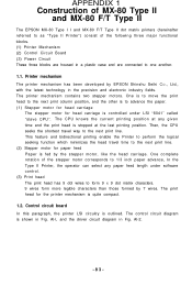
... stepper motors. Al-l, and the driver circuit diagram in a plastic case and are connected to one another. 1.1. The control circuit diagram is outlined. Printer mechanism The printer mechanism has been developed by 7 wires. APPENDIX 1 Construction of MX-80 Type II and MX-80 F/T Type II The EPSON MX-80 Type I I and MX-80 F/T Type II dot matrix printers (hereinafter referred to as "Type...
... stepper motors. Al-l, and the driver circuit diagram in a plastic case and are connected to one another. 1.1. The control circuit diagram is outlined. Printer mechanism The printer mechanism has been developed by 7 wires. APPENDIX 1 Construction of MX-80 Type II and MX-80 F/T Type II The EPSON MX-80 Type I I and MX-80 F/T Type II dot matrix printers (hereinafter referred to as "Type...

Operation Manual
Page 91
1.3. This line should be initiated remotely by a TTL driver or its equivalent. Printer initialization Printer initialization is accomplished in either of the two ways described below. (1) Initialization takes place automatically each time the primary AC power source is interrupted and ...
1.3. This line should be initiated remotely by a TTL driver or its equivalent. Printer initialization Printer initialization is accomplished in either of the two ways described below. (1) Initialization takes place automatically each time the primary AC power source is interrupted and ...


