Technical Brief (Impact Printers)
Page 1
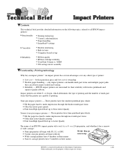
...over any other type of ownership Flexible paper handling - EPSON impact printers are capable of their reliability with tireless printheads and superior quality ribbons. Impact printers are the property of printing. These printers have finer printhead pins which: Hit the paper less hard to make impressions...Quality LLL The name of an EPSON's impact printer tells you if it has a narrow or wide carriage: LLL L Nine-pin printers all begin with FX, LX, or DFX Twenty-four pin printers all have 3 numbers in their names Narrow carriage printers have paper loaded and waiting. ...
...over any other type of ownership Flexible paper handling - EPSON impact printers are capable of their reliability with tireless printheads and superior quality ribbons. Impact printers are the property of printing. These printers have finer printhead pins which: Hit the paper less hard to make impressions...Quality LLL The name of an EPSON's impact printer tells you if it has a narrow or wide carriage: LLL L Nine-pin printers all begin with FX, LX, or DFX Twenty-four pin printers all have 3 numbers in their names Narrow carriage printers have paper loaded and waiting. ...

Service Manual
Page 6
... 1-10 1.2.6 Default Setting Mode 2 1-11 1.2.6.1 Setting Items 1-11 1.2.7 EEPROM Clear Function 1-12 1.2.8 Bi-D Adjustment 1-13 OPERATING PRICIPLES 2.1 MAIN COMPONENTS 2-1 2.1.1 C229MAIN Board 2-1 2.1.2 C229PSB/PSE/PSH Board 2-1 2.2 PRINTER MECHANISM 2-2 2.2.1 Printhead ...2-2 2.2.2 Paper Feed Mechanism 2-2 2.2.3 Carriage Movement Mechanism 2-2 2.2.4 Tractor Feed Mechanism 2-2 2.2.5 Platen Gap Adjustment Mechanism 2-2 2.2.6 Ribbon Feed Mechanism 2-2 2.3 CIRCUIT OPERATION 2-4 2.3.1 C229PSB/PSE/PSH Power Supply Circuit...
... 1-10 1.2.6 Default Setting Mode 2 1-11 1.2.6.1 Setting Items 1-11 1.2.7 EEPROM Clear Function 1-12 1.2.8 Bi-D Adjustment 1-13 OPERATING PRICIPLES 2.1 MAIN COMPONENTS 2-1 2.1.1 C229MAIN Board 2-1 2.1.2 C229PSB/PSE/PSH Board 2-1 2.2 PRINTER MECHANISM 2-2 2.2.1 Printhead ...2-2 2.2.2 Paper Feed Mechanism 2-2 2.2.3 Carriage Movement Mechanism 2-2 2.2.4 Tractor Feed Mechanism 2-2 2.2.5 Platen Gap Adjustment Mechanism 2-2 2.2.6 Ribbon Feed Mechanism 2-2 2.3 CIRCUIT OPERATION 2-4 2.3.1 C229PSB/PSE/PSH Power Supply Circuit...

Service Manual
Page 7
... THE POWER SUPPLY BOARD 3-11 3.4 UNIT REPAIRING OF THE MAIN BOARD 3-13 3.5 REPAIRING THE PRINTER MECHANISM 3-16 DISASSEMBLY AND ASSEMBLY 4.1 OVERVIEW 4-1 4.1.1 Disassembly Precautions 4-1 4.1.2 Tools and Instruments 4-1 4.1.3 Service Check After Repair 4-2 4.1.4 Abbreviations for Small Parts 4-3 4.2 DISASSEMBLY AND ASSEMBLY 4-4 4.2.1 Printhead Removal 4-5 4.2.2 HP (Home Position) Detector Removal 4-6 4.2.3 Pre-disassembly Procedures 4-7 4.2.4 Upper Housing Removal 4-8 4.2.5 C229MAIN Board...
... THE POWER SUPPLY BOARD 3-11 3.4 UNIT REPAIRING OF THE MAIN BOARD 3-13 3.5 REPAIRING THE PRINTER MECHANISM 3-16 DISASSEMBLY AND ASSEMBLY 4.1 OVERVIEW 4-1 4.1.1 Disassembly Precautions 4-1 4.1.2 Tools and Instruments 4-1 4.1.3 Service Check After Repair 4-2 4.1.4 Abbreviations for Small Parts 4-3 4.2 DISASSEMBLY AND ASSEMBLY 4-4 4.2.1 Printhead Removal 4-5 4.2.2 HP (Home Position) Detector Removal 4-6 4.2.3 Pre-disassembly Procedures 4-7 4.2.4 Upper Housing Removal 4-8 4.2.5 C229MAIN Board...
Service Manual
Page 18
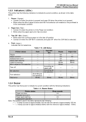
... Paper eject warning OOO Illegal panel operation O Note: The symbols used in the overheated condition. 2. FX-1880/880 Service Manual Chapter 1 Product Description 1.2.3 Indicators ( LEDs ) This printer has the following indicators to indicate its current condition, as bin selection Blinks Pause On On...font selections. Pause ( Orange ) • Comes On when the printer is paused, and goes Off when the printer is not paused. • Blinks when the Micro adjust function and the Font selection are enabled or the printhead is in the table below: 1. Tear Off / Bin ( ...
... Paper eject warning OOO Illegal panel operation O Note: The symbols used in the overheated condition. 2. FX-1880/880 Service Manual Chapter 1 Product Description 1.2.3 Indicators ( LEDs ) This printer has the following indicators to indicate its current condition, as bin selection Blinks Pause On On...font selections. Pause ( Orange ) • Comes On when the printer is paused, and goes Off when the printer is not paused. • Blinks when the Micro adjust function and the Font selection are enabled or the printhead is in the table below: 1. Tear Off / Bin ( ...

Service Manual
Page 25
... timing. 2.2.4 Tractor Feed Mechanism The tractor feed mechanism feeds continuous paper to the printhead and ejects it to the tractor unit setting positions and the lever positions. 2.2 PRINTER MECHANISM FX-1180/FX-880 Service Manual Chapter 2 Operating Principles This printer mechanism consists of Printhead, Paper feed mechanism, Carriage movement mechanism, Tractor feed mechanism, Platen gap adjustment...
... timing. 2.2.4 Tractor Feed Mechanism The tractor feed mechanism feeds continuous paper to the printhead and ejects it to the tractor unit setting positions and the lever positions. 2.2 PRINTER MECHANISM FX-1180/FX-880 Service Manual Chapter 2 Operating Principles This printer mechanism consists of Printhead, Paper feed mechanism, Carriage movement mechanism, Tractor feed mechanism, Platen gap adjustment...
Service Manual
Page 27
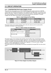
... current / voltage protection circuit is included.) F 35V 6% 0.8A Applications Logic lines Detectors Panel Switches & LEDs CR Motor PF Motor Printhead The power supply circuit consists of the line filter circuit, ZC-RCC (Zero-Cross Ringing Choke Converter) switching circuit and 5V chopper regulator...outputs voltages used to drive the printer control circuit and drive the mechanism. O v e r C u r r e n t p r o te c tio n - 2.3 CIRCUIT OPERATION FX-1180/FX-880 Service Manual Chapter 2 Operating Principles 2.3.1 C229PSB/PSE/PSH Power Supply Circuit This printer can be powered by the ...
... current / voltage protection circuit is included.) F 35V 6% 0.8A Applications Logic lines Detectors Panel Switches & LEDs CR Motor PF Motor Printhead The power supply circuit consists of the line filter circuit, ZC-RCC (Zero-Cross Ringing Choke Converter) switching circuit and 5V chopper regulator...outputs voltages used to drive the printer control circuit and drive the mechanism. O v e r C u r r e n t p r o te c tio n - 2.3 CIRCUIT OPERATION FX-1180/FX-880 Service Manual Chapter 2 Operating Principles 2.3.1 C229PSB/PSE/PSH Power Supply Circuit This printer can be powered by the ...
Service Manual
Page 28
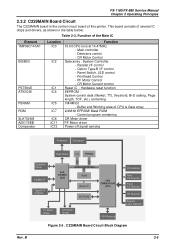
...function EEPROM : System control data (Market, TTL threshold, Bi-D setting, Page length, TOF, etc.) containing 1M/4M bit - Printhead Control - Main controller - Buffer and Working area of the Main IC Element TMP96C141AF E05B50 PST594E AT93C46 PSRAM ROM SLA7024M A2917SEB Comparator ... T h e r m is the control circuit board of several IC chips and drivers, as shown in the table below: Table 2-3. FX-1180/FX-880 Service Manual Chapter 2 Operating Principles 2.3.2 C229MAIN Board Circuit The C229MAIN board is to r Figure 2-5 . Detectors control - This board consists of ...
...function EEPROM : System control data (Market, TTL threshold, Bi-D setting, Page length, TOF, etc.) containing 1M/4M bit - Printhead Control - Main controller - Buffer and Working area of the Main IC Element TMP96C141AF E05B50 PST594E AT93C46 PSRAM ROM SLA7024M A2917SEB Comparator ... T h e r m is the control circuit board of several IC chips and drivers, as shown in the table below: Table 2-3. FX-1180/FX-880 Service Manual Chapter 2 Operating Principles 2.3.2 C229MAIN Board Circuit The C229MAIN board is to r Figure 2-5 . Detectors control - This board consists of ...

Service Manual
Page 29
B 2-6 FX-1180/FX-880 Service Manual Chapter 2 Operating Principles Data from the host computer is stored in the input buffer once, then converted into image data and transmitted to the printhead through the gate array, as shown in the figure below: H o s t c o m p u te r P r in th e a d d r iv e r c ir c u it Rev. Data Flow In p u t b u ffe r Im a g e b u ffe r RAM P r in t d a ta c o n v e r s io n Im a g e d a ta tra n s fe r CPU D a ta la tc h and d a ta o u tp u t G a te a rra y Figure 2-6.
B 2-6 FX-1180/FX-880 Service Manual Chapter 2 Operating Principles Data from the host computer is stored in the input buffer once, then converted into image data and transmitted to the printhead through the gate array, as shown in the figure below: H o s t c o m p u te r P r in th e a d d r iv e r c ir c u it Rev. Data Flow In p u t b u ffe r Im a g e b u ffe r RAM P r in t d a ta c o n v e r s io n Im a g e d a ta tra n s fe r CPU D a ta la tc h and d a ta o u tp u t G a te a rra y Figure 2-6.
Service Manual
Page 32
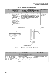
... from Main Board and check it with Printer Power off .) Check the following: − From the base to the collector − From the base to check #1 pin of the Printhead solenoid. Test pin numbers match the printhead solenoid (dot wire) numbers. Rev. Specifications 8.19...Printhead Connenctor Figure 3-2. Printhead Connector Pin Alignment Transistor Numbers Q2, Q3, Q4, Q5, Q6,Q7, Q8, Q9, Q10 ,Q11,Q12, Q13, Q14, Q15, Q16, Q17, Q18, Q19, Q20 Table 3-3. Meter Reading The tester shows neither open nor shorted. Printhead Driver Test Pin Test Method (Set meter to diodes. FX-1180/FX...
... from Main Board and check it with Printer Power off .) Check the following: − From the base to the collector − From the base to check #1 pin of the Printhead solenoid. Test pin numbers match the printhead solenoid (dot wire) numbers. Rev. Specifications 8.19...Printhead Connenctor Figure 3-2. Printhead Connector Pin Alignment Transistor Numbers Q2, Q3, Q4, Q5, Q6,Q7, Q8, Q9, Q10 ,Q11,Q12, Q13, Q14, Q15, Q16, Q17, Q18, Q19, Q20 Table 3-3. Meter Reading The tester shows neither open nor shorted. Printhead Driver Test Pin Test Method (Set meter to diodes. FX-1180/FX...
Service Manual
Page 33
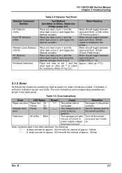
...Remedies Paper out error Paper Out: On Pause: On Release lever Pause: ON error Fatal error All LEDs : Blink *** ----- The printer fails to a wrong position. Note: Symbols used in the table represent the following: "∗" : A beep sounds for approx. 100 ms with... on . FX-1180/FX-880 Service Manual Chapter 3 Troubleshooting Detector Connector Number HP Detector (CN4) Front PE Detector (CN6) Release Lever Detector (CN10) PG Detector (CN11) Printhead thermistor Table 3-4 Detector Test Point Test Method (Set Meter to Ohms. Check the Printer power off the printer once and...
...Remedies Paper out error Paper Out: On Pause: On Release lever Pause: ON error Fatal error All LEDs : Blink *** ----- The printer fails to a wrong position. Note: Symbols used in the table represent the following: "∗" : A beep sounds for approx. 100 ms with... on . FX-1180/FX-880 Service Manual Chapter 3 Troubleshooting Detector Connector Number HP Detector (CN4) Front PE Detector (CN6) Release Lever Detector (CN10) PG Detector (CN11) Printhead thermistor Table 3-4 Detector Test Point Test Method (Set Meter to Ohms. Check the Printer power off the printer once and...

Service Manual
Page 35
... when power is turned on YES C229PSB/PSE/PSH blown? YES Replace the C229MAIN. Flowchart (1) Rev. 1. START FX-1180/FX-880 Service Manual Chapter 3 Troubleshooting Is AC input NO voltage normal? 120V version: 85 - 138V 230V version:... No fluctuation from AC voltage range is on. Are the resistances NO normal? YES Verify each motor and printhead solenoid resistance,referring to operate when power is permitted. Replace the applied unit. B 3-5 END Replace the ... at pin 7 or 8 of CN2 on C229PSB/PSE/PSH. Printer fails to Table 3-1 and Table 3-2.
... when power is turned on YES C229PSB/PSE/PSH blown? YES Replace the C229MAIN. Flowchart (1) Rev. 1. START FX-1180/FX-880 Service Manual Chapter 3 Troubleshooting Is AC input NO voltage normal? 120V version: 85 - 138V 230V version:... No fluctuation from AC voltage range is on. Are the resistances NO normal? YES Verify each motor and printhead solenoid resistance,referring to operate when power is permitted. Replace the applied unit. B 3-5 END Replace the ... at pin 7 or 8 of CN2 on C229PSB/PSE/PSH. Printer fails to Table 3-1 and Table 3-2.

Service Manual
Page 37
... voltage normal? YES Replace the C229 PSB/PSE/PSH. Are the resistances NO normal? Replace the applied unit. Figure 3-6. FX-1180/FX-880 Service Manual Chapter 3 Troubleshooting 3. YES Verify each motor and printhead solenoid resistance,referring to Table 3-1 and Table 3-2. No fluctuation from AC voltage range is permitted. END Replace the C229 PSB...
... voltage normal? YES Replace the C229 PSB/PSE/PSH. Are the resistances NO normal? Replace the applied unit. Figure 3-6. FX-1180/FX-880 Service Manual Chapter 3 Troubleshooting 3. YES Verify each motor and printhead solenoid resistance,referring to Table 3-1 and Table 3-2. No fluctuation from AC voltage range is permitted. END Replace the C229 PSB...
Service Manual
Page 45
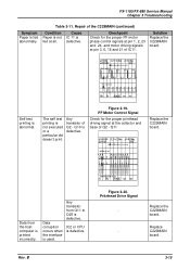
...The self test printing is defective. Q10 is not executed or a particular dot doesn't print. Q11 Replace the C229MAIN board. Any transistor from the ...Cause Paper is not IC 11 is defective. Any transistor of Q5 Figure 3-20. Checkpoint Check for the proper printhead driving signal at pin 3, 6, 18 and 21 of IC 8 Self test printing is used. Data corruption occurs... abnormal. Pin 1 of IC11 Pin 3 of IC11. Figure 3-19. IC2 or CPU is fed abnormally. FX-1180/FX-880 Service Manual Chapter 3 Troubleshooting Symptom Paper is defective. BASE of Q2 - Table 3-11. PF Motor ...
...The self test printing is defective. Q10 is not executed or a particular dot doesn't print. Q11 Replace the C229MAIN board. Any transistor from the ...Cause Paper is not IC 11 is defective. Any transistor of Q5 Figure 3-20. Checkpoint Check for the proper printhead driving signal at pin 3, 6, 18 and 21 of IC 8 Self test printing is used. Data corruption occurs... abnormal. Pin 1 of IC11 Pin 3 of IC11. Figure 3-19. IC2 or CPU is fed abnormally. FX-1180/FX-880 Service Manual Chapter 3 Troubleshooting Symptom Paper is defective. BASE of Q2 - Table 3-11. PF Motor ...

Service Manual
Page 46
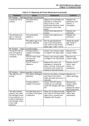
...and the left or right end, defective. Table 3-12. the printhead or the the main board main board. FX-1180/FX-880 Service Manual Chapter 3 Troubleshooting 3.5 REPAIRING THE PRINTER MECHANISM For detailed procedures for replacing or adjusting matter, refer to ...operate. Repairing the Printer Mechanism Symptom Cause Checkpoint Solution w Problem: The CR motor fails...
...and the left or right end, defective. Table 3-12. the printhead or the the main board main board. FX-1180/FX-880 Service Manual Chapter 3 Troubleshooting 3.5 REPAIRING THE PRINTER MECHANISM For detailed procedures for replacing or adjusting matter, refer to ...operate. Repairing the Printer Mechanism Symptom Cause Checkpoint Solution w Problem: The CR motor fails...
Service Manual
Page 47
FX-1180/FX-880 Service Manual Chapter 3 Troubleshooting Table 3-13. ... the ribbon feed mechanism. Rev. w Problem: Paper is not Set the gap adjustment properly adjusted. The printer tries to feed when the carriage moves in the paper path. The PF motor dose Check if any foreign...in reverse and engages with the gear. Adjust the platen gap. A particular dot is The printhead is abnormal. broken. lever to Chapter 5. mechanism. defective. Replace the printhead. density is not executed. resistance. B 3-17 Remove the foreign matter....
FX-1180/FX-880 Service Manual Chapter 3 Troubleshooting Table 3-13. ... the ribbon feed mechanism. Rev. w Problem: Paper is not Set the gap adjustment properly adjusted. The printer tries to feed when the carriage moves in the paper path. The PF motor dose Check if any foreign...in reverse and engages with the gear. Adjust the platen gap. A particular dot is The printhead is abnormal. broken. lever to Chapter 5. mechanism. defective. Replace the printhead. density is not executed. resistance. B 3-17 Remove the foreign matter....

Service Manual
Page 50
... and adhesives (See Chapter 6.) T Adjust the printer only in the manner described in this manual. Tool and Instrument List Name Specification EPSON Part No. Any adjustments required after printing. Failure... to the AC outlet, as it is connected to do so might cause personal injury. T Be careful with the printhead...below lists the tools and the instruments required for FX-1180 has been made since the major mechanical difference between FX-1180 and FX-880 is because no assembly procedures are commercially available...
... and adhesives (See Chapter 6.) T Adjust the printer only in the manner described in this manual. Tool and Instrument List Name Specification EPSON Part No. Any adjustments required after printing. Failure... to the AC outlet, as it is connected to do so might cause personal injury. T Be careful with the printhead...below lists the tools and the instruments required for FX-1180 has been made since the major mechanical difference between FX-1180 and FX-880 is because no assembly procedures are commercially available...
Service Manual
Page 51
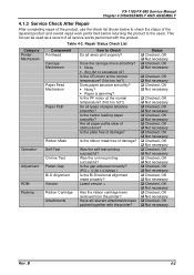
... the ribbon mask free of damage? Latest version = Has the ribbon cartridge been removed from the printer? Repair Status Check List Category Printer Mechanism Component Printhead Carriage Mechanism Paper Feed Mechanism Paper Path Operation Adjustment ROM Packing Ribbon Mask Self-Test On-line Test...adjusted correctly? (PG = 0.38 ± 0.02mm ) Is the Bi-Directional alignment made properly? Is the plate free of damage? FX-1180/FX-880 Service Manual Chapter 4 DISASSEMBLY AND ASSEMBLY 4.1.3 Service Check After Repair After completing repair of the product, use the check list shown below...
... the ribbon mask free of damage? Latest version = Has the ribbon cartridge been removed from the printer? Repair Status Check List Category Printer Mechanism Component Printhead Carriage Mechanism Paper Feed Mechanism Paper Path Operation Adjustment ROM Packing Ribbon Mask Self-Test On-line Test...adjusted correctly? (PG = 0.38 ± 0.02mm ) Is the Bi-Directional alignment made properly? Is the plate free of damage? FX-1180/FX-880 Service Manual Chapter 4 DISASSEMBLY AND ASSEMBLY 4.1.3 Service Check After Repair After completing repair of the product, use the check list shown below...

Service Manual
Page 54
... right after printing. $'-8670(17 After replacing the printhead, perform the platen gap adjustment. (Refer to Chapter 5.) C B S (M 3 x 8 ) P r in th e a d H ead FFC Figure 4-2. B 4-5 T Be careful with the printer when you handle it, as it . Printhead Removal Rev. Disconnect the head FFC from the AC power socket. FX-1180/FX-880 Service Manual Chapter 4 DISASSEMBLY AND ASSEMBLY...
... right after printing. $'-8670(17 After replacing the printhead, perform the platen gap adjustment. (Refer to Chapter 5.) C B S (M 3 x 8 ) P r in th e a d H ead FFC Figure 4-2. B 4-5 T Be careful with the printer when you handle it, as it . Printhead Removal Rev. Disconnect the head FFC from the AC power socket. FX-1180/FX-880 Service Manual Chapter 4 DISASSEMBLY AND ASSEMBLY...

Service Manual
Page 73
.... Required Adjustment Required Adjustment Printhead Removal or { Platen Gap Replacement Printer Mechanism Replacement Printer Mechanism Removal -{-- Main Boar... Replacement Timing Belt Replacement Platen Replacement Carriage Assembly -{{{-- Replacement CR Motor Replacement --- { EEPROM Clear Note 1) " Ÿ :Adjustment required. --- The following table shows the tools required for each adjustment. Note 2) "---" :Adjustment not required. Table 5-2. Table 5-1. 5.1 ADJUSTMENT OVERVIEW FX-1180/FX...
.... Required Adjustment Required Adjustment Printhead Removal or { Platen Gap Replacement Printer Mechanism Replacement Printer Mechanism Removal -{-- Main Boar... Replacement Timing Belt Replacement Platen Replacement Carriage Assembly -{{{-- Replacement CR Motor Replacement --- { EEPROM Clear Note 1) " Ÿ :Adjustment required. --- The following table shows the tools required for each adjustment. Note 2) "---" :Adjustment not required. Table 5-2. Table 5-1. 5.1 ADJUSTMENT OVERVIEW FX-1180/FX...
Service Manual
Page 74
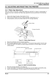
... the hexagon nut securing the PG adjust lever and the SHAFT,CR,GUIDE a little. 9. FX-1180/FX-880 Service Manual Chapter 5 Adjustment 5.2 ADJUSTING AND RESETTING THE PRINTER 5.2.1 Platen Gap Adjustment When the SHAFT,CR,GUIDE or BUSHING,PARALLEL,ADJUST is rotated or reassembled..., or printing is too faint or stained, the Platen Gap adjustment must be performed in the following order: 1. Attach the printhead...
... the hexagon nut securing the PG adjust lever and the SHAFT,CR,GUIDE a little. 9. FX-1180/FX-880 Service Manual Chapter 5 Adjustment 5.2 ADJUSTING AND RESETTING THE PRINTER 5.2.1 Platen Gap Adjustment When the SHAFT,CR,GUIDE or BUSHING,PARALLEL,ADJUST is rotated or reassembled..., or printing is too faint or stained, the Platen Gap adjustment must be performed in the following order: 1. Attach the printhead...


