Technical Brief (Impact Printers)
Page 1
... L Nine-pin printers all begin with LQ FX-980-Nine-pin narrow carriage Wide carriage printers have 4 number in their names Narrow carriage printers have 3 numbers in their names EPSON Sales Training EPSON is a 9- MTBF M Off-carriage motor assembly Functionality-Printing technology LL Why buy an impact printer? EPSON impact printers are either 9- These printers have the sturdiest printhead pins which...
... L Nine-pin printers all begin with LQ FX-980-Nine-pin narrow carriage Wide carriage printers have 4 number in their names Narrow carriage printers have 3 numbers in their names EPSON Sales Training EPSON is a 9- MTBF M Off-carriage motor assembly Functionality-Printing technology LL Why buy an impact printer? EPSON impact printers are either 9- These printers have the sturdiest printhead pins which...

Service Manual
Page 22
... table ) Fonts: Draft, NLQ Roman, NLQ Saris serif 1-13 ESC/P mode - IBM mode - 1.2.1.8 Reliability MCBF 5 million lines (excluding a printhead) (MCBF: Mean Cycles Between Failures) MTBF (expected value) 4000 power on hours (duty cycle 25Yo) - 80-column model 6000 power on hours ...(duty cycle 25Yo) -136-column model (MTBF : Mean Time Between Failures) Printhead Life 100 million characters (14 dots/character) REV.-A 1.2.1.9 Safety Approvals Safety standards UL1950 with D3 CSA22.2#220 EN 60950 (TUV) (U.S.A model) (EUR model) R.F.I FCC...
... table ) Fonts: Draft, NLQ Roman, NLQ Saris serif 1-13 ESC/P mode - IBM mode - 1.2.1.8 Reliability MCBF 5 million lines (excluding a printhead) (MCBF: Mean Cycles Between Failures) MTBF (expected value) 4000 power on hours (duty cycle 25Yo) - 80-column model 6000 power on hours ...(duty cycle 25Yo) -136-column model (MTBF : Mean Time Between Failures) Printhead Life 100 million characters (14 dots/character) REV.-A 1.2.1.9 Safety Approvals Safety standards UL1950 with D3 CSA22.2#220 EN 60950 (TUV) (U.S.A model) (EUR model) R.F.I FCC...

Service Manual
Page 33
...length. If it has received a form feed). This function can be turned off the printer. (The control panel is still operational in the default setting mode. 1.5.8 Thermal Protection When the printhead temperature exceeds 82 deg. Then, the maximum number of the sheet and saved in use.... Self Test Printout When the paper-out sensor detects a paper out, the printer enters the pause condition automatically after it occurs, the :"...
...length. If it has received a form feed). This function can be turned off the printer. (The control panel is still operational in the default setting mode. 1.5.8 Thermal Protection When the printhead temperature exceeds 82 deg. Then, the maximum number of the sheet and saved in use.... Self Test Printout When the paper-out sensor detects a paper out, the printer enters the pause condition automatically after it occurs, the :"...
Service Manual
Page 35
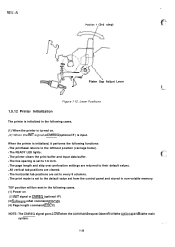
... 4.- q All vertical tab positions are set to every 8 columns. q The print mode is set to 1/6 inch. When the printer is input. Lever Positions 1.5.12 Printer Initialization The printer is initialized in the following functions: q The printhead returns to their default values. REV.-A Position 1 (3rd step) &'"$\\ -=. . . TOF position will be reset in the following cases...
... 4.- q All vertical tab positions are set to every 8 columns. q The print mode is set to 1/6 inch. When the printer is input. Lever Positions 1.5.12 Printer Initialization The printer is initialized in the following functions: q The printhead returns to their default values. REV.-A Position 1 (3rd step) &'"$\\ -=. . . TOF position will be reset in the following cases...
Service Manual
Page 42
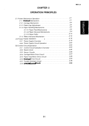
CHAPTER 2 OPERATION PRINCIPLES REV.-A 2.1 Printer Mechanism Operation 2. .-.1 2.1.1 Printhead Mechanism 2. .-.1 2.1.2 Carriage Mechanism 2. .-.3 2.1.3 Platen Gap Adjustment 2. . -. 4 2.1.4 Paper Handling Mechanisms 2. .-5 2.1.4.1 Paper Feed Mechanisms 2. .-5 2.1.4.2 Paper Advance Mechanisms 2. . -6 2.1.4.3 Paper Paths 2....Reset Circuit 2. .-.25 2.3.3 Sensor Circuits 2. .-.26 2.3.4 Carriage Motor Drive Circuit 2. .-27 2.3.5 Paper Feed Motor Drive Circuit 2. .-28 2.3.6 Printhead Drive Circuit 2. -. 23 2.3.7 Parallel Interface Circuit 2. .-29 2.3.8 2-30 E2pRoM Control circuit Z.i
CHAPTER 2 OPERATION PRINCIPLES REV.-A 2.1 Printer Mechanism Operation 2. .-.1 2.1.1 Printhead Mechanism 2. .-.1 2.1.2 Carriage Mechanism 2. .-.3 2.1.3 Platen Gap Adjustment 2. . -. 4 2.1.4 Paper Handling Mechanisms 2. .-5 2.1.4.1 Paper Feed Mechanisms 2. .-5 2.1.4.2 Paper Advance Mechanisms 2. . -6 2.1.4.3 Paper Paths 2....Reset Circuit 2. .-.25 2.3.3 Sensor Circuits 2. .-.26 2.3.4 Carriage Motor Drive Circuit 2. .-27 2.3.5 Paper Feed Motor Drive Circuit 2. .-28 2.3.6 Printhead Drive Circuit 2. -. 23 2.3.7 Parallel Interface Circuit 2. .-29 2.3.8 2-30 E2pRoM Control circuit Z.i
Service Manual
Page 43
... Table 2-3. Paper Path for Push-pull Tractor Feeding Using the FronEtntrence....2-l7 Figure 2-21. Platen Gap Adjust Lever 2. .-4 Figure 2-4. Printhead Drive Circuit 2. -29 Figure 2-30. REV.-A LIST OF FIGURES Figure 2-l. Howthe Printhead Works 2-2 Figure 2-2. Push-Pull Tractor Operation Using the Rear Paper Entrance........2-lO Figure 2-9. Push-pull Tractor Operation Using the Front...
... Table 2-3. Paper Path for Push-pull Tractor Feeding Using the FronEtntrence....2-l7 Figure 2-21. Platen Gap Adjust Lever 2. .-4 Figure 2-4. Printhead Drive Circuit 2. -29 Figure 2-30. REV.-A LIST OF FIGURES Figure 2-l. Howthe Printhead Works 2-2 Figure 2-2. Push-Pull Tractor Operation Using the Rear Paper Entrance........2-lO Figure 2-9. Push-pull Tractor Operation Using the Front...

Service Manual
Page 44
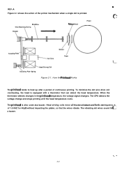
... hits the platen, the rebounding force of the plate spring. The FX-870/l 170 printer mechanism features a 9-pin impact dot printhead for seriaI Printin9. The plate then returns to its original position. 2-1 2.1 Printer Mechanism Operation REV.-A This section describes the printer mechanism of the printhead itself, the ink ribbon, and the platen. Each of these wires has...
... hits the platen, the rebounding force of the plate spring. The FX-870/l 170 printer mechanism features a 9-pin impact dot printhead for seriaI Printin9. The plate then returns to its original position. 2-1 2.1 Printer Mechanism Operation REV.-A This section describes the printer mechanism of the printhead itself, the ink ribbon, and the platen. Each of these wires has...
Service Manual
Page 45
... stops printing until the head temperature cools. c--.-.,". The printhead is printed. To minimize the dot wire drive coil overheating, the head is equipped with a thermistor that the wires vibrate. REV.-A Figure 2-1 shows the action of the printer mechanism when a single dot is also used asa buzzer. Dot Wire Wire Resetting Spring Stopper \ \ Ribbon Mask Platen...
... stops printing until the head temperature cools. c--.-.,". The printhead is printed. To minimize the dot wire drive coil overheating, the head is equipped with a thermistor that the wires vibrate. REV.-A Figure 2-1 shows the action of the printer mechanism when a single dot is also used asa buzzer. Dot Wire Wire Resetting Spring Stopper \ \ Ribbon Mask Platen...

Service Manual
Page 46
NOTE: Carriage initialization for the 80-coIumn and 136-column models are different. The home position (HP) sensor detects the home position of the carriage. Carriage Operation 2-3 Puny Timing Belt / CR w 'etec'Or'Hp >\\!!! "~\\d-\@0/3A Base Frame \ '\ w Figure 2-2. The carriage (CR)motor (a stepping motor) drives the timin9 belt which moves the carriage. REV.-A ' 2.1.2 Carriage Mechanism The timing belt is connected to the lower side of the carriage. With the printhead installed, the carriage moves in either direction along the carriage guide shaft.
NOTE: Carriage initialization for the 80-coIumn and 136-column models are different. The home position (HP) sensor detects the home position of the carriage. Carriage Operation 2-3 Puny Timing Belt / CR w 'etec'Or'Hp >\\!!! "~\\d-\@0/3A Base Frame \ '\ w Figure 2-2. The carriage (CR)motor (a stepping motor) drives the timin9 belt which moves the carriage. REV.-A ' 2.1.2 Carriage Mechanism The timing belt is connected to the lower side of the carriage. With the printhead installed, the carriage moves in either direction along the carriage guide shaft.

Service Manual
Page 47
... Gap Adjustment &>., Theplatengap (the gap between the platen andtheprinthead) can beadjustedto allowthe printerto use paper a of the printerto protect the printhead. This rotation moves the carriage either toward or away from the top) turns off the platen gap switch, which slows down the... printing speed of differentweights orthicknesses. The PG detector detects the position of the adjust lever. t Platen Gap ~m, Adjustment Slot . -. .::, Printhead $---- When the platen gap adjust lever is 0.38mm * 0.02mm with the adjust lever set to position 2 (the 5th slot from the...
... Gap Adjustment &>., Theplatengap (the gap between the platen andtheprinthead) can beadjustedto allowthe printerto use paper a of the printerto protect the printhead. This rotation moves the carriage either toward or away from the top) turns off the platen gap switch, which slows down the... printing speed of differentweights orthicknesses. The PG detector detects the position of the adjust lever. t Platen Gap ~m, Adjustment Slot . -. .::, Printhead $---- When the platen gap adjust lever is 0.38mm * 0.02mm with the adjust lever set to position 2 (the 5th slot from the...

Service Manual
Page 57
... Tractor Feeding Using the Rear Entrance 2-14 The rear entrance can be used , the rear PE detector senses when the paper is out. Paper (Continuous) \ Printhead / \\ f Detector, PE (Rear) Paper Guide Rollers Figure 2-14. Paper Path for Push Tractor Feeding Using the Rear Entrance .
... Tractor Feeding Using the Rear Entrance 2-14 The rear entrance can be used , the rear PE detector senses when the paper is out. Paper (Continuous) \ Printhead / \\ f Detector, PE (Rear) Paper Guide Rollers Figure 2-14. Paper Path for Push Tractor Feeding Using the Rear Entrance .

Service Manual
Page 58
Paper Path for Push-pull Tractor FeedingUsing the Rear Entrance (3) Bottom entrance Figure 2-16 shows the paper path fortractorfeeding using the bottom entrance. REV.-A Paper (Continu Printhead ctor ear) Paper Guide Rollers Figure 2-15. Paper (Continuous) Paper Detector, PE (Front) \ Lower Paper Guide Roller Figure 2-16. The bottom entrance is out. When the bottom entrance is used, the front PE detector senses when the paper is used only for pull tractor feeding. Paper Path for Pull Tractor Feeding Using the Bottom Entrance 2-15
Paper Path for Push-pull Tractor FeedingUsing the Rear Entrance (3) Bottom entrance Figure 2-16 shows the paper path fortractorfeeding using the bottom entrance. REV.-A Paper (Continu Printhead ctor ear) Paper Guide Rollers Figure 2-15. Paper (Continuous) Paper Detector, PE (Front) \ Lower Paper Guide Roller Figure 2-16. The bottom entrance is out. When the bottom entrance is used, the front PE detector senses when the paper is used only for pull tractor feeding. Paper Path for Pull Tractor Feeding Using the Bottom Entrance 2-15

Service Manual
Page 62
... of a short circuit. Power Supply Output Voltages and Applications Output voltage (DC) Applications +35 v CR (carriage) motor drive PF (paper feed) motor drive Printhead drive +5 v Main control board logic circuitry Sensors Control panel LEDs PF (paper feed) motor hold 2-19 Fuse F1 (2.5A/125 V for C076 PSB or ...1.25 lV250 V for C076 pSE) is powered by these two DC voltages. 2.2 Power Supply Operation REV.-A The FX-870/l 170 printer is used to Protect the Power suPPIY circuit of each board in case of the two power supply boards: 120 VAC power supply board...
... of a short circuit. Power Supply Output Voltages and Applications Output voltage (DC) Applications +35 v CR (carriage) motor drive PF (paper feed) motor drive Printhead drive +5 v Main control board logic circuitry Sensors Control panel LEDs PF (paper feed) motor hold 2-19 Fuse F1 (2.5A/125 V for C076 PSB or ...1.25 lV250 V for C076 pSE) is powered by these two DC voltages. 2.2 Power Supply Operation REV.-A The FX-870/l 170 printer is used to Protect the Power suPPIY circuit of each board in case of the two power supply boards: 120 VAC power supply board...

Service Manual
Page 66
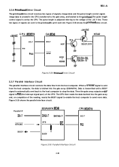
Image data -L transfer ~ Input buffer ~ Image buffer Figure 2-24. Data sent from the host computer to the printhead through the gate array. Data Flow 2-23 CPU El- -1 Printdata conversion - - - REV.-A Figure 2-24 shows the data flow from the host computer is converted to image data and transmitted to the printhead.
Image data -L transfer ~ Input buffer ~ Image buffer Figure 2-24. Data sent from the host computer to the printhead through the gate array. Data Flow 2-23 CPU El- -1 Printdata conversion - - - REV.-A Figure 2-24 shows the data flow from the host computer is converted to image data and transmitted to the printhead.

Service Manual
Page 67
Functions of Main Components of the C094 MAIN. Also controls various printer mechanism parts, such as the top-of-form position. . E05A66YA (IC4) This gate array mainly performs the following five functions: " Memory management q Centronics l/F control q Control panel control q E2PROM control q Printhead drive circuit control PROM (IC3) The PROM contains the program that... functions of the main components of C094 MAIN IC or Circuit Functions TMP90C041F (2C1) Receives data from the host computer and loads it to the printhead drive circuit. Table 2-5.
Functions of Main Components of the C094 MAIN. Also controls various printer mechanism parts, such as the top-of-form position. . E05A66YA (IC4) This gate array mainly performs the following five functions: " Memory management q Centronics l/F control q Control panel control q E2PROM control q Printhead drive circuit control PROM (IC3) The PROM contains the program that... functions of the main components of C094 MAIN IC or Circuit Functions TMP90C041F (2C1) Receives data from the host computer and loads it to the printhead drive circuit. Table 2-5.

Service Manual
Page 69
...v ~ RELEASE LEVER +35 Voltage Monitor Head Temperature +35 v ,., ,.\ {. ~ ," Vref ZD1 7)7 Figure 2-26. If the printhead temperature exceeds the maximum level, the printer stops printing until the temperature drops to supply the reference voltage for the A/D convertor in the CPU. When the...to a certain level. Sensor Circuit Block Diagram 2-26 The CPU constantly monitors the printhead temperature. The +35 V monitor circuit is a thermistor. REV.-A 2.3.3 Sensor Circuits .>~ ( The FX-870/l 170 printer has the following sensors: CRHOME, pE (FRONT), pE (REAR), pG (platen...
...v ~ RELEASE LEVER +35 Voltage Monitor Head Temperature +35 v ,., ,.\ {. ~ ," Vref ZD1 7)7 Figure 2-26. If the printhead temperature exceeds the maximum level, the printer stops printing until the temperature drops to supply the reference voltage for the A/D convertor in the CPU. When the...to a certain level. Sensor Circuit Block Diagram 2-26 The CPU constantly monitors the printhead temperature. The +35 V monitor circuit is a thermistor. REV.-A 2.3.3 Sensor Circuits .>~ ( The FX-870/l 170 printer has the following sensors: CRHOME, pE (FRONT), pE (REAR), pG (platen...
Service Manual
Page 72
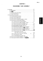
...is adjusted referring to P82 (the interrupt signal port) of the reading, resets the BUSY signal to enable the host computer to the printhead. Data is transmitted until a BUSY signal is sent from the host computer. Figure 2-30 shows the parallel interface circuit. Parallel Interface Circuit... 2-29 When a STROBE signal is automatically sent back to the host computer to print each dot. These two types of signals; Parallel l/F DO-7 STROBE BUSY - E05A66YA (IC4) DINO-7 DATAO-7 - Image data is set by the CPU...
...is adjusted referring to P82 (the interrupt signal port) of the reading, resets the BUSY signal to enable the host computer to the printhead. Data is transmitted until a BUSY signal is sent from the host computer. Figure 2-30 shows the parallel interface circuit. Parallel Interface Circuit... 2-29 When a STROBE signal is automatically sent back to the host computer to print each dot. These two types of signals; Parallel l/F DO-7 STROBE BUSY - E05A66YA (IC4) DINO-7 DATAO-7 - Image data is set by the CPU...
Service Manual
Page 74
....-A 3.1 Overview ...3. -. 1 3.1.1 Precautions 3. .-1 3.1.2 TooIS 3. .-1 3.1.3 Service Checks After Repair 3. .-2 3.1.4 Screw Specifications 3. . -. 3 3.2 Disassembly and Assembly 3. .-.4 3.2.1 Pre-disessembly Procedures 3. .-5 3.2.2 Removing the PANEL UNIT 3. .-6 3.2.3 Removing the PRINTHEAD 3. .-7 3.2.4 Removing the HOUSING ASSEMBLY, UPPER 3. -8 3.2.5 Removing the PRINTER MECHANISM 3. -9 3.2.5.1 Removing the PLATEN ASSEMBLY 3. -1o 3.2.5.2 Removing the FRAME ASSEMBLY, REAR 3-11 3.2.5.3 Removing the MOTOR ASSEMBLY, CR 3. -12 3.2.5.4 Removing the MOTOR ASSEMBLY...
....-A 3.1 Overview ...3. -. 1 3.1.1 Precautions 3. .-1 3.1.2 TooIS 3. .-1 3.1.3 Service Checks After Repair 3. .-2 3.1.4 Screw Specifications 3. . -. 3 3.2 Disassembly and Assembly 3. .-.4 3.2.1 Pre-disessembly Procedures 3. .-5 3.2.2 Removing the PANEL UNIT 3. .-6 3.2.3 Removing the PRINTHEAD 3. .-7 3.2.4 Removing the HOUSING ASSEMBLY, UPPER 3. -8 3.2.5 Removing the PRINTER MECHANISM 3. -9 3.2.5.1 Removing the PLATEN ASSEMBLY 3. -1o 3.2.5.2 Removing the FRAME ASSEMBLY, REAR 3-11 3.2.5.3 Removing the MOTOR ASSEMBLY, CR 3. -12 3.2.5.4 Removing the MOTOR ASSEMBLY...

Service Manual
Page 75
.... Removing the BOARD ASSEMBLY, C084 MAIN 3-23 Figure 3-26. Removing the PRINTER MECHANISM 3. -9 figure 3-8. Positioning the LEVER, RELEASE for Disassembling the Printer 3. -4 Figure 3-2. Equipment Required for Repaired Printer 3. -2 Table 3-4. Removing the PIATEN ASSEMBLY 3. -1o Figure 3-9. Removing the PANEL UNIT 3.6 Figure 3-4. Removing the PRINTHEAD 3. -7 Figure 3-6. Removing the DETECTOR, PG 3. -18 Figure 3-20. Table 3-1. Removing the...
.... Removing the BOARD ASSEMBLY, C084 MAIN 3-23 Figure 3-26. Removing the PRINTER MECHANISM 3. -9 figure 3-8. Positioning the LEVER, RELEASE for Disassembling the Printer 3. -4 Figure 3-2. Equipment Required for Repaired Printer 3. -2 Table 3-4. Removing the PIATEN ASSEMBLY 3. -1o Figure 3-9. Removing the PANEL UNIT 3.6 Figure 3-4. Removing the PRINTHEAD 3. -7 Figure 3-6. Removing the DETECTOR, PG 3. -18 Figure 3-20. Table 3-1. Removing the...

Service Manual
Page 77
...correct temperature and not overheating? Is the bidirectional alignment adjusted correctly? Inspection Checklist for Repaired Printer Category Printer features Component Printhead • Carriage mechanism Items to note the current state of paper in the printer feeding smoothly? Is Check Required? Is the platen gap adjusted correctly? Is rib•bon... ead Printi•ng ROM version Is pa•per advancing smoothly? REV.-A 3.1.3 Service Checks After Repair Before you send the printer back to the customer, fill in the checklist in Table 3-3 to Check Are any wires worn out?
...correct temperature and not overheating? Is the bidirectional alignment adjusted correctly? Inspection Checklist for Repaired Printer Category Printer features Component Printhead • Carriage mechanism Items to note the current state of paper in the printer feeding smoothly? Is Check Required? Is the platen gap adjusted correctly? Is rib•bon... ead Printi•ng ROM version Is pa•per advancing smoothly? REV.-A 3.1.3 Service Checks After Repair Before you send the printer back to the customer, fill in the checklist in Table 3-3 to Check Are any wires worn out?


