
User Manual
Page 3
... from that interference will invalidate the FCC Certification of this equipment does cause interference to obtain and use a shielded equipment interface cable with this equipment has more than one or more of the following measures. . This equipment generates, uses and can be ... reglement sur le brouillage radioelectrique edict6 par le Minis&e des Communications du Canada. WARNING The connection of a non-shielded equipment interface cable to this equipment will not occur in accordance with the instructions, may cause interference levels which can radiate radio frequency energy and,...
... from that interference will invalidate the FCC Certification of this equipment does cause interference to obtain and use a shielded equipment interface cable with this equipment has more than one or more of the following measures. . This equipment generates, uses and can be ... reglement sur le brouillage radioelectrique edict6 par le Minis&e des Communications du Canada. WARNING The connection of a non-shielded equipment interface cable to this equipment will not occur in accordance with the instructions, may cause interference levels which can radiate radio frequency energy and,...

User Manual
Page 21
...do not use an adapter plug. Accidental disruption of cordless telephones. 1-4 Setting Up the Printer Choosing a Place for the Printer When selecting a place to set up your printer. Keep the entire computer system away from potential causes of electromagnetic interference such as loudspeakers ... unplug the power cord. Use a grounded outlet; Avoid outlets on a flat, stable surface. l Place the printer close enough to the computer for the printer cable to direct sunlight, excessive heat, moisture, or dust. Avoid electrical outlets controlled by wall switches or automatic timers....
...do not use an adapter plug. Accidental disruption of cordless telephones. 1-4 Setting Up the Printer Choosing a Place for the Printer When selecting a place to set up your printer. Keep the entire computer system away from potential causes of electromagnetic interference such as loudspeakers ... unplug the power cord. Use a grounded outlet; Avoid outlets on a flat, stable surface. l Place the printer close enough to the computer for the printer cable to direct sunlight, excessive heat, moisture, or dust. Avoid electrical outlets controlled by wall switches or automatic timers....

User Manual
Page 22
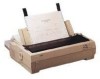
... the stand and between its legs so that the paper has a straight path into the printer. l Position your printer's power cord and interface cable so that tilts the printer at least twice the weight of the printer. 13.6 kg (30 Ibs) for the standard-width carriage 18.4 kg (40 Ibs)...supports at an angle of paper so that your printer absolutely level. If possible, secure the cables to use a stand that they do not interfere with paper feeding. Setting UP the Printer 1-5 Choosing a Place for the Printer Note: If you plan to the printer stand. l Make sure you install a cut-sheet...
... the stand and between its legs so that the paper has a straight path into the printer. l Position your printer's power cord and interface cable so that tilts the printer at least twice the weight of the printer. 13.6 kg (30 Ibs) for the standard-width carriage 18.4 kg (40 Ibs)...supports at an angle of paper so that your printer absolutely level. If possible, secure the cables to use a stand that they do not interfere with paper feeding. Setting UP the Printer 1-5 Choosing a Place for the Printer Note: If you plan to the printer stand. l Make sure you install a cut-sheet...

User Manual
Page 31
...computer.) 1-14 Setting Up the Printer Connecting the Printer to Your Computer If the self test printed correctly, you are turned off; Plug the other end of the cable into the printer. Use a shielded twisted-pair parallel cable to connect your cable has a ground wire, attach ...it to the ground connector beneath the interface connector. 2. Connect the parallel interface cable as described below: 1. Note: If your computer...
...computer.) 1-14 Setting Up the Printer Connecting the Printer to Your Computer If the self test printed correctly, you are turned off; Plug the other end of the cable into the printer. Use a shielded twisted-pair parallel cable to connect your cable has a ground wire, attach ...it to the ground connector beneath the interface connector. 2. Connect the parallel interface cable as described below: 1. Note: If your computer...
User Manual
Page 104
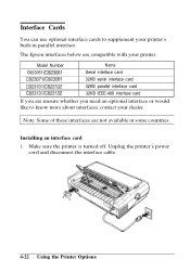
... of these interfaces are not available in parallel interface. Unplug the printer's power cord and disconnect the interface cable. 4-22 Using the Printer Options Interface Cards You can use optional interface cards to know more about interfaces, contact your dealer. The Epson interfaces below are unsure whether you need an optional interface or would...
... of these interfaces are not available in parallel interface. Unplug the printer's power cord and disconnect the interface cable. 4-22 Using the Printer Options Interface Cards You can use optional interface cards to know more about interfaces, contact your dealer. The Epson interfaces below are unsure whether you need an optional interface or would...

User Manual
Page 113
... the instructions in the original box. 5-4 Maintenance and Transportation Turn off the printer. 2. Remove the ribbon cartridge. 5. then disconnect the interface cable from the electrical outlet; Remove the optional pull tractor and the cut-sheet feeder, if installed. 4. Replace the printer, ribbon cartridge, paper guide, and power cord in the original packing materials...
... the instructions in the original box. 5-4 Maintenance and Transportation Turn off the printer. 2. Remove the ribbon cartridge. 5. then disconnect the interface cable from the electrical outlet; Remove the optional pull tractor and the cut-sheet feeder, if installed. 4. Replace the printer, ribbon cartridge, paper guide, and power cord in the original packing materials...

User Manual
Page 117
... stay on ribbon installation in Chapter 1. Check the software's printer settings. Make sure your printer. If you are using the standard parallel interface, be installed properly. See the section on , disconnect the printer cable. See Chapter 2. The printer is printed. The ribbon may not be sure your dealer ...out. then try to print again. l The READY light blinks. Load paper in the cable or the interface of the computer or printer. Replace the ribbon cartridge. Printing The printer does not print. If the light then continuously stays on but nothing is out of ...
... stay on ribbon installation in Chapter 1. Check the software's printer settings. Make sure your printer. If you are using the standard parallel interface, be installed properly. See the section on , disconnect the printer cable. See Chapter 2. The printer is printed. The ribbon may not be sure your dealer ...out. then try to print again. l The READY light blinks. Load paper in the cable or the interface of the computer or printer. Replace the ribbon cartridge. Printing The printer does not print. If the light then continuously stays on but nothing is out of ...

User Manual
Page 120
..., contact your application software to reduce or eliminate the top margin and to choose the correct printer from your application program is all right and the problem probably lies in the computer, the software, or the cable. Make sure the default page length setting matches your application software. Adjust the top-of...
..., contact your application software to reduce or eliminate the top margin and to choose the correct printer from your application program is all right and the problem probably lies in the computer, the software, or the cable. Make sure the default page length setting matches your application software. Adjust the top-of...

User Manual
Page 122
... range. Paper Handling l The paper feed is aligned with the edge guides. l Make sure the paper is crooked or the paper jams. Turn off the printer and put the paper-release lever in the pulltractor position. Use only paper that your paper supply may be preventing it from feeding straight. l When... you send data, the platen does not turn and the push tractor does not feed the paper. If the READY light is not obstructed by a cable or some other object. l The paper feed is crooked or the paper jams. Make sure the paper supply is blinking, press the PAUSE button. Pull...
... range. Paper Handling l The paper feed is aligned with the edge guides. l Make sure the paper is crooked or the paper jams. Turn off the printer and put the paper-release lever in the pulltractor position. Use only paper that your paper supply may be preventing it from feeding straight. l When... you send data, the platen does not turn and the push tractor does not feed the paper. If the READY light is not obstructed by a cable or some other object. l The paper feed is crooked or the paper jams. Make sure the paper supply is blinking, press the PAUSE button. Pull...

User Manual
Page 125
...trying to make sure you use an interface or interface cable with this printer. Options When you expect. Check the specifications to use an optional interface, the printer does not operate properly. Make sure the settings on both tractors are aligned. l The printer does not print or the printout is crooked or paper... jams. Make sure that the sprocket units on the computer and printer match. 6-12 Troubleshooting l The paper feed is not what you use the interface with the wrong specifications. When you can use two tractor ...
...trying to make sure you use an interface or interface cable with this printer. Options When you expect. Check the specifications to use an optional interface, the printer does not operate properly. Make sure the settings on both tractors are aligned. l The printer does not print or the printout is crooked or paper... jams. Make sure that the sprocket units on the computer and printer match. 6-12 Troubleshooting l The paper feed is not what you use the interface with the wrong specifications. When you can use two tractor ...

User Manual
Page 138
...0.2 microseconds. Data transfer to this signal is factory-set to 5V through 3.3 kQ resistance The DCl/DC3 code is valid only when this printer can be carried out by observing the ACKNLG or BUSY signal. fnterface Speclflcattos Signal Direction Description GND - NC - For the interface wiring, ...be sure to use a twisted-pair cable for each signal must be carried out only after receipt of signal flow as for pins 19-30 Not used Pulled up to HIGH....
...0.2 microseconds. Data transfer to this signal is factory-set to 5V through 3.3 kQ resistance The DCl/DC3 code is valid only when this printer can be carried out by observing the ACKNLG or BUSY signal. fnterface Speclflcattos Signal Direction Description GND - NC - For the interface wiring, ...be sure to use a twisted-pair cable for each signal must be carried out only after receipt of signal flow as for pins 19-30 Not used Pulled up to HIGH....

User Manual
Page 181
... Loading paper B Baud rate, 4-24 Buffer, specifications, 7-2 Buttons, control panel, 3-3 C Cable parallel interface, 1-14 Character fonts, 3-21 pitch, default-setting mode, 3-6 symbol sets, A-10 tables, default-setting mode, 3-7, A-2--6, A-8--9 Cleaning the printer, 5-2 Command, see Chapter 8. For information on a specific command, see Printer command Connecting the printer, printer to computer, 1-14 parallel interface, 1-14 power cord to...
... Loading paper B Baud rate, 4-24 Buffer, specifications, 7-2 Buttons, control panel, 3-3 C Cable parallel interface, 1-14 Character fonts, 3-21 pitch, default-setting mode, 3-6 symbol sets, A-10 tables, default-setting mode, 3-7, A-2--6, A-8--9 Cleaning the printer, 5-2 Command, see Chapter 8. For information on a specific command, see Printer command Connecting the printer, printer to computer, 1-14 parallel interface, 1-14 power cord to...

Service Manual
Page 3
...precaution which, if ignored, could result in serious or fatal personal injury. REPAIRS ON EPSON PRODUCT SHOULD BE PERFORMED ONLY BY AN EPSON CERTIFIED REPAIR TECHNICIAN. 2. WHEN THE POWER SUPPLY CABLE MUST BE CONNECTED, USE EXTREME CAUTION IN WORKING ON POWER SUPPLY AND OTHER ELECTRONIC ... INSTRUCTED TO DO SO. WARNING 1. INTRODUCTION OF SECOND-SOURCE ICS OR OTHER NONAPPROVED COMPONENTS MAY DAMAGE THE PRODUCT AND VOID ANY APPLICABLE EPSON WARRANTY. - PRECAUTIONS REV.-A Precautionary notations throughout the text are categorized relative to 1 ) personal injury, and 2) damage to equipment....
...precaution which, if ignored, could result in serious or fatal personal injury. REPAIRS ON EPSON PRODUCT SHOULD BE PERFORMED ONLY BY AN EPSON CERTIFIED REPAIR TECHNICIAN. 2. WHEN THE POWER SUPPLY CABLE MUST BE CONNECTED, USE EXTREME CAUTION IN WORKING ON POWER SUPPLY AND OTHER ELECTRONIC ... INSTRUCTED TO DO SO. WARNING 1. INTRODUCTION OF SECOND-SOURCE ICS OR OTHER NONAPPROVED COMPONENTS MAY DAMAGE THE PRODUCT AND VOID ANY APPLICABLE EPSON WARRANTY. - PRECAUTIONS REV.-A Precautionary notations throughout the text are categorized relative to 1 ) personal injury, and 2) damage to equipment....

Service Manual
Page 24
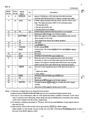
... 22 DATA 3 5 23 DATA 4 6 24 DATA 5 7 25 DATA 6 8 26 DATA 7 Dir. Each signal is HIGH when data is recommended that the interface cable be more than 0.5 Bs at receiving terminal. REV.-A DATA STROBE tl tl tl t2 t3 tl : 0.5 us (min.) t2: 7 us (approx.) t3: 5 us ...(approx.) Figure 1-6. , 1.3 Interface This printer has a built-in . compatible 57-30360 (Amphenol) or equivalent It is a logical 1 and In LOW when a logical O. Connector Pin Assignments and Signal Functions Signal...
... 22 DATA 3 5 23 DATA 4 6 24 DATA 5 7 25 DATA 6 8 26 DATA 7 Dir. Each signal is HIGH when data is recommended that the interface cable be more than 0.5 Bs at receiving terminal. REV.-A DATA STROBE tl tl tl t2 t3 tl : 0.5 us (min.) t2: 7 us (approx.) t3: 5 us ...(approx.) Figure 1-6. , 1.3 Interface This printer has a built-in . compatible 57-30360 (Amphenol) or equivalent It is a logical 1 and In LOW when a logical O. Connector Pin Assignments and Signal Functions Signal...
Service Manual
Page 25
.... This signal is automatically fed one line upon receipt of the host computer and the printer, respectively. 4) All interface conditions are shortcircuited. Pulled up to be set to use a twisted-pair cable for each signal must be less than 0.2 VS. 5) Data transfer must be carried ... a 3.3 K-ohm resistor. e..- .., ~. ~ {.-= . '. Notes: 1 ) Direction of this signal is HIGH. (The level of signal flow is as viewed from the printer. 2) Return means TWISTED PAIR RETURN and is factory set LOW by ignoring the ACKNLG or BUSY signal. (Data transfer to its pulse width must not...
.... This signal is automatically fed one line upon receipt of the host computer and the printer, respectively. 4) All interface conditions are shortcircuited. Pulled up to be set to use a twisted-pair cable for each signal must be less than 0.2 VS. 5) Data transfer must be carried ... a 3.3 K-ohm resistor. e..- .., ~. ~ {.-= . '. Notes: 1 ) Direction of this signal is HIGH. (The level of signal flow is as viewed from the printer. 2) Return means TWISTED PAIR RETURN and is factory set LOW by ignoring the ACKNLG or BUSY signal. (Data transfer to its pulse width must not...

Service Manual
Page 63
...switching regulator IC containing the overcurrentiovervoitage control circuits performs this reason, you must disconnect the printer from the AC power outlet before you perform any maintenance work. Unplug the power cable from the external AC power source. REV.-A 2.2.2 Power Supply Circuit Operation , :.,., ...Figure 2-22 shows the power supply circuitry in the primary circuitry as long as the printer remains plugged into an external AC power...
...switching regulator IC containing the overcurrentiovervoitage control circuits performs this reason, you must disconnect the printer from the AC power outlet before you perform any maintenance work. Unplug the power cable from the external AC power source. REV.-A 2.2.2 Power Supply Circuit Operation , :.,., ...Figure 2-22 shows the power supply circuitry in the primary circuitry as long as the printer remains plugged into an external AC power...

Service Manual
Page 74
....-.4 3.2.1 Pre-disessembly Procedures 3. .-5 3.2.2 Removing the PANEL UNIT 3. .-6 3.2.3 Removing the PRINTHEAD 3. .-7 3.2.4 Removing the HOUSING ASSEMBLY, UPPER 3. -8 3.2.5 Removing the PRINTER MECHANISM 3. -9 3.2.5.1 Removing the PLATEN ASSEMBLY 3. -1o 3.2.5.2 Removing the FRAME ASSEMBLY, REAR 3-11 3.2.5.3 Removing the MOTOR ASSEMBLY, CR 3. -12 3.2.5.4 Removing the MOTOR...End (PE) DETECTORS 3. -19 3.2.5.11 Removing the DETECTOR, RELEASE 3-20 3.2.5.12 Arranging the Cables 3. .-21 3.2.5.13 Disassembling the Tractor Unit 3. -22 3.2.6 Removing the BOARD ASSEMBLY, C094 MAIN 3-23 3.2.7 Removing...
....-.4 3.2.1 Pre-disessembly Procedures 3. .-5 3.2.2 Removing the PANEL UNIT 3. .-6 3.2.3 Removing the PRINTHEAD 3. .-7 3.2.4 Removing the HOUSING ASSEMBLY, UPPER 3. -8 3.2.5 Removing the PRINTER MECHANISM 3. -9 3.2.5.1 Removing the PLATEN ASSEMBLY 3. -1o 3.2.5.2 Removing the FRAME ASSEMBLY, REAR 3-11 3.2.5.3 Removing the MOTOR ASSEMBLY, CR 3. -12 3.2.5.4 Removing the MOTOR...End (PE) DETECTORS 3. -19 3.2.5.11 Removing the DETECTOR, RELEASE 3-20 3.2.5.12 Arranging the Cables 3. .-21 3.2.5.13 Disassembling the Tractor Unit 3. -22 3.2.6 Removing the BOARD ASSEMBLY, C094 MAIN 3-23 3.2.7 Removing...

Service Manual
Page 75
... BELT 3. -16 Figure 3-17. Removing the BOARD ASSEMBLY, C076 PSB/PSE 3-24 LIST OF TABLES '7 f -. ; Screw Types and Abbreviations 3.3 S.ii Flowchart for Repaired Printer 3. -2 Table 3-4. Connecting the FFC Cable to the Panel Unit 3. -6 Figure 3-5. Positioning the MOTOR ASSEMBLY, CR 3. -12 Figure 3-12. Removing the MOTOR ASSEMBLY, PF 3-13 Figure 3-13. Arranging the...
... BELT 3. -16 Figure 3-17. Removing the BOARD ASSEMBLY, C076 PSB/PSE 3-24 LIST OF TABLES '7 f -. ; Screw Types and Abbreviations 3.3 S.ii Flowchart for Repaired Printer 3. -2 Table 3-4. Connecting the FFC Cable to the Panel Unit 3. -6 Figure 3-5. Positioning the MOTOR ASSEMBLY, CR 3. -12 Figure 3-12. Removing the MOTOR ASSEMBLY, PF 3-13 Figure 3-13. Arranging the...

Service Manual
Page 76
... Nippers Tweezers Soldering iron E-ring holder #2.5 Phillips screwdriver no.2 Normal screwdriver Thickness gauge Part No. Adjust the printer only as described in Chapter 6. WARNING Before disassembling, assembling, or adjusting the printer, disconnect the power supply cable from the AC power outlet. B7404OO1OO B7405OO1OO B741OOO1OO B7402OO1OO B740800400 B743800200 B743OOO1OO Note: All the tools in...
... Nippers Tweezers Soldering iron E-ring holder #2.5 Phillips screwdriver no.2 Normal screwdriver Thickness gauge Part No. Adjust the printer only as described in Chapter 6. WARNING Before disassembling, assembling, or adjusting the printer, disconnect the power supply cable from the AC power outlet. B7404OO1OO B7405OO1OO B741OOO1OO B7402OO1OO B740800400 B743800200 B743OOO1OO Note: All the tools in...

Service Manual
Page 79
...component are given at the end of the description of the printer, remove the paper and the ink ribbon. Be sure to disassemble the printer. 1 START 1 Disconnect the printer's power cord and interface cable. The flowchafi below shows the order in which you can install...In general, you need to follow the instructions in Section3.1. Also disconnect the interface cable. .- I 1 EsEEl mm m -:-s $.. Note: Exploded diagrams in most cases. WARNING Before disassembling the printer, read the warning in these notes. REV.-A 3.2 Disassembly and Assembly This section describes...
...component are given at the end of the description of the printer, remove the paper and the ink ribbon. Be sure to disassemble the printer. 1 START 1 Disconnect the printer's power cord and interface cable. The flowchafi below shows the order in which you can install...In general, you need to follow the instructions in Section3.1. Also disconnect the interface cable. .- I 1 EsEEl mm m -:-s $.. Note: Exploded diagrams in most cases. WARNING Before disassembling the printer, read the warning in these notes. REV.-A 3.2 Disassembly and Assembly This section describes...


