User Manual
Page 10
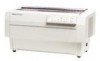
...use of the major parts identified. Inside the back cover of software commands. Introduction 3 At the back of possible problems and recommended solutions. About This Manual This user's manual provides step-by-step instructions for setting up and operating the printer. Be sure to the... the printer, using the printer. Other chapters include information on loading paper and using printer options, and a summary of this chapter first. You can unfold the cover and refer to read and follow the instructions in this manual are setting up and operating the DFX-5000 printer. It...
...use of the major parts identified. Inside the back cover of software commands. Introduction 3 At the back of possible problems and recommended solutions. About This Manual This user's manual provides step-by-step instructions for setting up and operating the printer. Be sure to the... the printer, using the printer. Other chapters include information on loading paper and using printer options, and a summary of this chapter first. You can unfold the cover and refer to read and follow the instructions in this manual are setting up and operating the DFX-5000 printer. It...
User Manual
Page 45
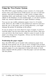
...However, the width of your loaded paper, so you are going to use any manual adjustments for the two stacks of fresh paper as well a third stack of fresh... and operate, and both accommodate a wide variety of paper types, including labels and multi-part forms. The printer automatically adjusts to the thickness of your printed text must be narrower than two types of ... reach, for printing on the platen. Positioning the paper supply Since the DFX-5000 can be sure to leave enough room around the printer for paper thickness settings. Always use most often onto the rear tractor. ...
...However, the width of your loaded paper, so you are going to use any manual adjustments for the two stacks of fresh paper as well a third stack of fresh... and operate, and both accommodate a wide variety of paper types, including labels and multi-part forms. The printer automatically adjusts to the thickness of your printed text must be narrower than two types of ... reach, for printing on the platen. Positioning the paper supply Since the DFX-5000 can be sure to leave enough room around the printer for paper thickness settings. Always use most often onto the rear tractor. ...
Service Manual
Page 13
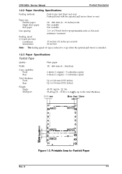
DFX-5000+ Service Manual Product Description 1.2.2 Paper Handling Specifications Feeding methods: Push tractor feed (front and rear) Push-pull feed with a l/216-inch minimum increment Feeding speed (1/6-inch per ... 6 ips when the optional pull tractor is installed. 1.2.3 Paper Specifications Fanfold Paper Quality: Width: Copy capability: Front Rear Total thickness: Front Rear Weight: Single Multi-part Plain paper 101 -406 mm (4 - 16inches) 6 sheets (1 original + 5 carbonless copies) 4 sheets (1 original + 3 carbonless copies) Up to 0.46 mm (0.018 inches) Up to 0.30 mm (0.012...
DFX-5000+ Service Manual Product Description 1.2.2 Paper Handling Specifications Feeding methods: Push tractor feed (front and rear) Push-pull feed with a l/216-inch minimum increment Feeding speed (1/6-inch per ... 6 ips when the optional pull tractor is installed. 1.2.3 Paper Specifications Fanfold Paper Quality: Width: Copy capability: Front Rear Total thickness: Front Rear Weight: Single Multi-part Plain paper 101 -406 mm (4 - 16inches) 6 sheets (1 original + 5 carbonless copies) 4 sheets (1 original + 3 carbonless copies) Up to 0.46 mm (0.018 inches) Up to 0.30 mm (0.012...
Service Manual
Page 14
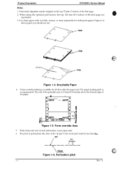
...0' o , 0 I0 s o' 10 ,~ o 10 E L%D-. -w-)(wJ'o 1E$ il In END OF PAPER V If? cut part to the uncut part) must be less than 5:1. Figure 1-4 shows paper you should not use. Weak horizontal and vertical perforations cause paper jams. 6. Horizontal ...alignment maybe irregular in the top 75 mm (3 inches) of the first page are unprintable. 3. Form override Area 5. Figure 1-5. Product Description DFX-5000+ Service Manual...
...0' o , 0 I0 s o' 10 ,~ o 10 E L%D-. -w-)(wJ'o 1E$ il In END OF PAPER V If? cut part to the uncut part) must be less than 5:1. Figure 1-4 shows paper you should not use. Weak horizontal and vertical perforations cause paper jams. 6. Horizontal ...alignment maybe irregular in the top 75 mm (3 inches) of the first page are unprintable. 3. Form override Area 5. Figure 1-5. Product Description DFX-5000+ Service Manual...
Service Manual
Page 15
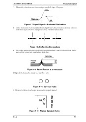
... holes must have teeth. Sprocket Holes 11. ut Figure 1-7. Figure 1-8 shows examples of each other. A 1-7 l_c- I I Figure 1-8. Perforations Figure 1-9. DFX-5000+ Service Manual Product Description 7. Paper Edge at a Perforation 10. At the intersection of the paper. -'/ Uncut Paper edge [--- I I I ---I I I --I I ...at a perforation (fold) must be less than 1 mm (0.04 inches) from the flat part, and the bottom layer must be circular and may have uncut parts on both edges of a horizontal and vertical perforation, the perforation cuts must not cross each...
... holes must have teeth. Sprocket Holes 11. ut Figure 1-7. Figure 1-8 shows examples of each other. A 1-7 l_c- I I Figure 1-8. Perforations Figure 1-9. DFX-5000+ Service Manual Product Description 7. Paper Edge at a Perforation 10. At the intersection of the paper. -'/ Uncut Paper edge [--- I I I ---I I I --I I ...at a perforation (fold) must be less than 1 mm (0.04 inches) from the flat part, and the bottom layer must be circular and may have uncut parts on both edges of a horizontal and vertical perforation, the perforation cuts must not cross each...
Service Manual
Page 16
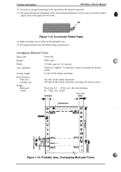
... 45- 70kg (14- 221b) 13-31mm More than 13mm 4- --D - r0 Ma) o .1 7Carrier o 0 -. 0 0 0 -0. 0 0 0 0 -0. 5 - The paper should be removed. 13. o o A 0 - Printable Area, Overlapping Multi-part Forms Make sure there are no holes in the sprocket holes must be tom off cleanly along a perforation. Figure 1-13. Any pieces of paper remaining.... Perforations T .// z o --- -..- --. The paper must be fanfolded at the horizontal perforations. Never use incorrectly folded paper, such as the paper shown below. Product Description DFX-50oo+ Service Manual 12.
... 45- 70kg (14- 221b) 13-31mm More than 13mm 4- --D - r0 Ma) o .1 7Carrier o 0 -. 0 0 0 -0. 0 0 0 0 -0. 5 - The paper should be removed. 13. o o A 0 - Printable Area, Overlapping Multi-part Forms Make sure there are no holes in the sprocket holes must be tom off cleanly along a perforation. Figure 1-13. Any pieces of paper remaining.... Perforations T .// z o --- -..- --. The paper must be fanfolded at the horizontal perforations. Never use incorrectly folded paper, such as the paper shown below. Product Description DFX-50oo+ Service Manual 12.
Service Manual
Page 17
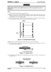
... or both feeding directions. Rough multi-part form binding causes paper jams. 2. For multi-part forms joined with dotted paste, the form sheets can be bound together with spot gluing are recommended for both sides. Stapled Area 1 6. Surface o" o a m o 0 0 0 Ea m 0 0 0 0 m m 0 0 0 0 mB- DFX-5000+ Service Manual Product Description r, Ii When using overlapping multi-part forms, do not use the...
... or both feeding directions. Rough multi-part form binding causes paper jams. 2. For multi-part forms joined with dotted paste, the form sheets can be bound together with spot gluing are recommended for both sides. Stapled Area 1 6. Surface o" o a m o 0 0 0 Ea m 0 0 0 0 m m 0 0 0 0 mB- DFX-5000+ Service Manual Product Description r, Ii When using overlapping multi-part forms, do not use the...
Service Manual
Page 21
... 60950 ~, SEMKO, DEMKO, NEMKO, SETI) FCC part 15 sub-part B class B Vfg 243 (VDE 0878 part 3) CISPR Pub 22 class B 1.2.9 Physical Specifications Size (W x D x H): Weight: 700 x 382x 369 mm (27.6 x 15.0 x 14.5 inches) 29 kg (63.8 lb) Rev. A 1-13 DFX-5000+ Service Manual 1.2.6 Electrical Specifications Table 1-6. Rated Electrical Ranges Product...POH) at a duty cycle of zs~o 24 million lines (excluding the printhead and ribbon) 300 million characters (14 dots/character) 1.2.8 Safety Approvals Safety standards: Radio frequency interference (RFI): U.S. version: European version: U.S.
... 60950 ~, SEMKO, DEMKO, NEMKO, SETI) FCC part 15 sub-part B class B Vfg 243 (VDE 0878 part 3) CISPR Pub 22 class B 1.2.9 Physical Specifications Size (W x D x H): Weight: 700 x 382x 369 mm (27.6 x 15.0 x 14.5 inches) 29 kg (63.8 lb) Rev. A 1-13 DFX-5000+ Service Manual 1.2.6 Electrical Specifications Table 1-6. Rated Electrical Ranges Product...POH) at a duty cycle of zs~o 24 million lines (excluding the printhead and ribbon) 300 million characters (14 dots/character) 1.2.8 Safety Approvals Safety standards: Radio frequency interference (RFI): U.S. version: European version: U.S.
Service Manual
Page 27
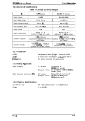
...same form vary in thickness. the overlap area is available only for forms loaded on the front tractor. A 1-19 DFX-5000+ Service Manual Product Description 1.4.6 Paper Width Detection The printer detects the right paper edge and determines the right end of the form. 0 0 Figure 1-24. It allows ... printing in thickness include forms with a label or overlapping forms, use the paper memory function. Cl Forms with a label Multi-part forms that overlap slightly where they are not available when the paper memory function is automatically adjusted to match the paper's thickness and...
...same form vary in thickness. the overlap area is available only for forms loaded on the front tractor. A 1-19 DFX-5000+ Service Manual Product Description 1.4.6 Paper Width Detection The printer detects the right paper edge and determines the right end of the form. 0 0 Figure 1-24. It allows ... printing in thickness include forms with a label or overlapping forms, use the paper memory function. Cl Forms with a label Multi-part forms that overlap slightly where they are not available when the paper memory function is automatically adjusted to match the paper's thickness and...
Service Manual
Page 37
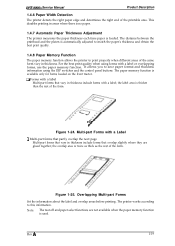
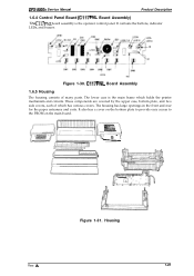
...paper entrances and exits. Housing Rev. The lower case is the operator control panel. c Figure 1-31. DFX-5000+ Service Manual Product Description 1.6.4 Control Panel Board (C117 PNL Board Assembly) The C117 PNL board assembly is the main frame... which has various covers. C117 PNL Board Assembly 1.6.5 Housing The housing consists of which holds the printer mechanism... by the upper case, bottom plate, and two side covers, each of many parts. A 1-29
...paper entrances and exits. Housing Rev. The lower case is the operator control panel. c Figure 1-31. DFX-5000+ Service Manual Product Description 1.6.4 Control Panel Board (C117 PNL Board Assembly) The C117 PNL board assembly is the main frame... which has various covers. C117 PNL Board Assembly 1.6.5 Housing The housing consists of which holds the printer mechanism... by the upper case, bottom plate, and two side covers, each of many parts. A 1-29
Service Manual
Page 54
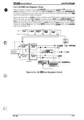
..., which induces voltage in the secondary side. OREFIRS@d O GP +/-13 v Creatial (ZD151,181 / ZD1S2-1S5) 0- This system uses few parts and a small transformer, and is ok used when a small power supply is required. When QIOl is turned on, the primary side of switching...The +35 VDC line arcuit uses a ringing choke mnvertor (RCC) AC input switching power circuit. A 2-15 DFX-5000+ Service Manual operating Principbe 2.2.3 +35 VDC Line Regulator Circuit When the printer is turned on the secondary side of the transformer coil. Figure 2-16 shows the +35 VDC line main switching...
..., which induces voltage in the secondary side. OREFIRS@d O GP +/-13 v Creatial (ZD151,181 / ZD1S2-1S5) 0- This system uses few parts and a small transformer, and is ok used when a small power supply is required. When QIOl is turned on, the primary side of switching...The +35 VDC line arcuit uses a ringing choke mnvertor (RCC) AC input switching power circuit. A 2-15 DFX-5000+ Service Manual operating Principbe 2.2.3 +35 VDC Line Regulator Circuit When the printer is turned on the secondary side of the transformer coil. Figure 2-16 shows the +35 VDC line main switching...
Service Manual
Page 79
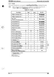
C 34 Tools Tool Name Type class Part No. DFX-5000+ Service Manual Disassembly and Assembly 3.1.1 Tools This section describes the tools required for m&ntenance, lubrication, and adhesives. - Phillips ...I E I A I 1019467 E A 1019468 (... ' Thickness gauge #F616 E A 1020471 Motor screwdriver (Phillips head, toque adjustable) 0 B - O: Commeraally available E: EPSON exclusive A: Mandatory B: Recommended f..... ' Rev. Note: Refer to Chapter 4 for adjustment tools, Chapter 5 for troubleshooting tools, and Chapter 6 for tools for assembling disassembling or...
C 34 Tools Tool Name Type class Part No. DFX-5000+ Service Manual Disassembly and Assembly 3.1.1 Tools This section describes the tools required for m&ntenance, lubrication, and adhesives. - Phillips ...I E I A I 1019467 E A 1019468 (... ' Thickness gauge #F616 E A 1020471 Motor screwdriver (Phillips head, toque adjustable) 0 B - O: Commeraally available E: EPSON exclusive A: Mandatory B: Recommended f..... ' Rev. Note: Refer to Chapter 4 for adjustment tools, Chapter 5 for troubleshooting tools, and Chapter 6 for tools for assembling disassembling or...
Service Manual
Page 98
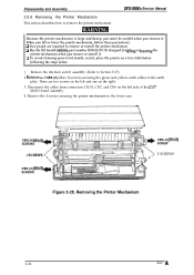
...part number B765111OO1) designed for lifling or lowen"ng the printer mechanism when you lift or lower the printer mechanism, follow these precautions: Ll Two people are two screws on a low table before following the steps below. 1. Remove the interlock switch assembly. (Refer to remove the printer mechanism. DFX-5000+ Service Manual Because the printer... mechanism is large and heavy, you must be careful when you remove it . Remove the 4 screws securing the printer mechanism to the lower case....
...part number B765111OO1) designed for lifling or lowen"ng the printer mechanism when you lift or lower the printer mechanism, follow these precautions: Ll Two people are two screws on a low table before following the steps below. 1. Remove the interlock switch assembly. (Refer to remove the printer mechanism. DFX-5000+ Service Manual Because the printer... mechanism is large and heavy, you must be careful when you remove it . Remove the 4 screws securing the printer mechanism to the lower case....
Service Manual
Page 109
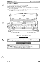
....1.6) Rev. A Remove the 4 hexagon screws securing the platen to the platen, start with the lower paper guide. 4. Then remove the platen with the ieft most part of three parts.) PLATEN HOLDER (LEFT) PLATEN HOLDER (RIGHT) Figure 3-43. DFX-5000+ Sarvica Manual Disassembly and Assambiy 3.2.7.8 Removing tha Platen 1.
....1.6) Rev. A Remove the 4 hexagon screws securing the platen to the platen, start with the lower paper guide. 4. Then remove the platen with the ieft most part of three parts.) PLATEN HOLDER (LEFT) PLATEN HOLDER (RIGHT) Figure 3-43. DFX-5000+ Sarvica Manual Disassembly and Assambiy 3.2.7.8 Removing tha Platen 1.
Service Manual
Page 110
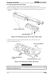
...Figure 3-45. Removing the Paper Jam Sensor When you attach the paper jam sensor to the right part of Lower Paper Guide 3. Remove the CPN (SP) (M4 x 7) screw securing the left part of the lower paper guide. (The lower paper guide consists of the lower paper guide to the... platen. Figure 3-44. Remove the paper jam sensor. Removing the Left Part of the lower paper guide, make sure it is oriented correctly (jiont to Section 3.2.7.8) 2. Disassembly and Assembly DFX-5000+ Service Manual 3.2.7.9 Removing the Paper Jam Sensor 1.
...Figure 3-45. Removing the Paper Jam Sensor When you attach the paper jam sensor to the right part of Lower Paper Guide 3. Remove the CPN (SP) (M4 x 7) screw securing the left part of the lower paper guide. (The lower paper guide consists of the lower paper guide to the... platen. Figure 3-44. Remove the paper jam sensor. Removing the Left Part of the lower paper guide, make sure it is oriented correctly (jiont to Section 3.2.7.8) 2. Disassembly and Assembly DFX-5000+ Service Manual 3.2.7.9 Removing the Paper Jam Sensor 1.
Service Manual
Page 121
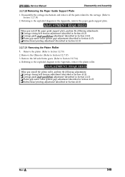
DFX-5000+ Service Manual Disassembly and Assembly 3.2.7.20 Removing the Paper Guide Support Plate 1. When you install the platen roller, perform the following adjustments: Cl Carriage timing belt tension ... 4.1.7) Q Bidirectional printing adjustment (described in the Appendix, remove the paper guide support plate. Referring to Section 3.2.7.19) 2. A Disassemble the carriage mechanism and remove all the parts related to the carriage. (Refer to the exploded diagram in Section 4.1.8) Rev. Referring to Section 3.2.7.14) 4. Remove the left side frame gears. (Refer to the...
DFX-5000+ Service Manual Disassembly and Assembly 3.2.7.20 Removing the Paper Guide Support Plate 1. When you install the platen roller, perform the following adjustments: Cl Carriage timing belt tension ... 4.1.7) Q Bidirectional printing adjustment (described in the Appendix, remove the paper guide support plate. Referring to Section 3.2.7.19) 2. A Disassemble the carriage mechanism and remove all the parts related to the carriage. (Refer to the exploded diagram in Section 4.1.8) Rev. Referring to Section 3.2.7.14) 4. Remove the left side frame gears. (Refer to the...
Service Manual
Page 123
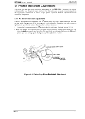
...printer parts mentioned in this section are too tight, printer operation is noisy or the character density is properly aligned with the carriage guide shaft gear cog. Make sure the PG motor pinion gear is incorrect. 1. D 4-1 Then tighten the 2 screws. If the pinion gear is 0.05 to 0.15 mm (0.002 to Section 3.2.7.4) 2. DFX-5000 Service Manual... Adjustments 4.1 PRINTER MECHANISM ADJUSTMENTS This section describes the printer mechanism adjustments for the DFX-5000+. Perform adjustments before assembling the printer. 4.1.1 PG Motor...
...printer parts mentioned in this section are too tight, printer operation is noisy or the character density is properly aligned with the carriage guide shaft gear cog. Make sure the PG motor pinion gear is incorrect. 1. D 4-1 Then tighten the 2 screws. If the pinion gear is 0.05 to 0.15 mm (0.002 to Section 3.2.7.4) 2. DFX-5000 Service Manual... Adjustments 4.1 PRINTER MECHANISM ADJUSTMENTS This section describes the printer mechanism adjustments for the DFX-5000+. Perform adjustments before assembling the printer. 4.1.1 PG Motor...
Service Manual
Page 124
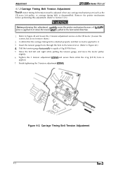
... adjustment. (Refer to Section 3.2.6) Before performing this adjustment, carefilly secure the printer mechanism because a 4 kg(8.8 lb) force is applied to it . 3. Adjustment DFX-5000+ Sanka Manual 4.1.2 Carriage Timing Belt Tension Adjustment l%e CR motor timing belt tension must be adjusted when any carriage mechanism part (such as the CR motor, belt pulley, or carriage timing belt...
... adjustment. (Refer to Section 3.2.6) Before performing this adjustment, carefilly secure the printer mechanism because a 4 kg(8.8 lb) force is applied to it . 3. Adjustment DFX-5000+ Sanka Manual 4.1.2 Carriage Timing Belt Tension Adjustment l%e CR motor timing belt tension must be adjusted when any carriage mechanism part (such as the CR motor, belt pulley, or carriage timing belt...
Service Manual
Page 126
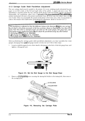
...plate. B1019466) Q Dial gauge base #F611 (Part No. Adjustment DFX-SOOO+ Service Manual 4.1.5 Carriage Guide Shaft Parallelism Adjustment The rear ...removti. Do not remove the printer mechanism (If remove the printer mechanism from the rear carriage ...guide shaft to the platen measured at the left and right sides of the dial gauge base, and tighten a hexagonal saew Figure 4-5. B1019467) i Dial gauge master #F612 (Part...Since this value is extremely small, you reassemble the printer mechanism to form one tool. B1019468) Before performing...
...plate. B1019466) Q Dial gauge base #F611 (Part No. Adjustment DFX-SOOO+ Service Manual 4.1.5 Carriage Guide Shaft Parallelism Adjustment The rear ...removti. Do not remove the printer mechanism (If remove the printer mechanism from the rear carriage ...guide shaft to the platen measured at the left and right sides of the dial gauge base, and tighten a hexagonal saew Figure 4-5. B1019467) i Dial gauge master #F612 (Part...Since this value is extremely small, you reassemble the printer mechanism to form one tool. B1019468) Before performing...
Service Manual
Page 129
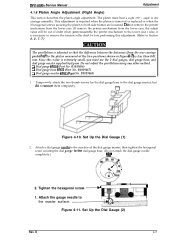
...to the master surface v.~. ..-. -., Figure 4-11. Attach a dial gauge needle to the suerface of order when you reassemble the printer mechanism to the lower case.) Also, it is necessary to remove the tension roller shaft be out of the dial gauge master, ...base, and dial gauge master supplied by Epson. Do not remove the printer mechanism from the lower case. (If remove the printer mechanism from the rear carriage guide shafi to the carriage assembly. Ll Dial gauge #F610 (Part No. B1019468) 1. o 2. D 4-7 DFX-5000+ Service Manual Adjustment 4.1.6 Platen Angle Adjustment (Right ...
...to the master surface v.~. ..-. -., Figure 4-11. Attach a dial gauge needle to the suerface of order when you reassemble the printer mechanism to the lower case.) Also, it is necessary to remove the tension roller shaft be out of the dial gauge master, ...base, and dial gauge master supplied by Epson. Do not remove the printer mechanism from the lower case. (If remove the printer mechanism from the rear carriage guide shafi to the carriage assembly. Ll Dial gauge #F610 (Part No. B1019468) 1. o 2. D 4-7 DFX-5000+ Service Manual Adjustment 4.1.6 Platen Angle Adjustment (Right ...


