
Service Manual
Page 79
...the AC power socket. The power switch is connected to the component level. B740400100 B740500100 B741000100 B740200100 B740800400 B743800200 B743000100 B776702201 Note: All tools are commercially available. Therefore, the printer's primary circuitry remains live even after the ... assembly. Rev.A 3-1 WARNING Before disassembling, assembling, or adjusting the printer, disconnect the power supply cable from the AC power socket. Standard screwdriver Thickness gauge Part No. LQ-2070 Service Manual Disassembly and Assembly 3.1 OVERVIEW This section describes various points to...
...the AC power socket. The power switch is connected to the component level. B740400100 B740500100 B741000100 B740200100 B740800400 B743800200 B743000100 B776702201 Note: All tools are commercially available. Therefore, the printer's primary circuitry remains live even after the ... assembly. Rev.A 3-1 WARNING Before disassembling, assembling, or adjusting the printer, disconnect the power supply cable from the AC power socket. Standard screwdriver Thickness gauge Part No. LQ-2070 Service Manual Disassembly and Assembly 3.1 OVERVIEW This section describes various points to...

Service Manual
Page 84
Removing the Panel Board Assembly 1. Remove the printer cover and ribbon cartridge (see Section 3.2.1). 2. The FFC must be connected properly, as shown in Figure 3-5. Remove the panel board assembly from the C165 PNL board assembly... Figure 3-5 Lock Cover for CN1 as shown in Figure 3-5, and release the FFC from CN1. Release the flexible flat cable (FFC) by pushing them from CN1, slide the lock cover for CN1 and the FFC Before disconnecting the FFC from ...and then disconnect the FFC for CN1, lock the lock cover . Disassembly and Assembly LQ-2070 Service Manual 3.2.2.
Removing the Panel Board Assembly 1. Remove the printer cover and ribbon cartridge (see Section 3.2.1). 2. The FFC must be connected properly, as shown in Figure 3-5. Remove the panel board assembly from the C165 PNL board assembly... Figure 3-5 Lock Cover for CN1 as shown in Figure 3-5, and release the FFC from CN1. Release the flexible flat cable (FFC) by pushing them from CN1, slide the lock cover for CN1 and the FFC Before disconnecting the FFC from ...and then disconnect the FFC for CN1, lock the lock cover . Disassembly and Assembly LQ-2070 Service Manual 3.2.2.
Service Manual
Page 91
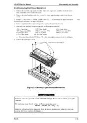
LQ-2070 Service Manual Disassembly and Assembly 3.2.9 Removing the Printer Mechanism 1. Remove 4 printer mechanism mounting screws securing the printer mechanism. 5. The tightening torque for CN10 and CN11 after releasing the connector locks by pulling up. 6. Remove 3 CBS screws... white) g Disconnect the cables for the printer mechanism mounting screw = 0.98 Nm ~ 1.18 Nm (10 ~ 12 Kg - Printer Mechanism Mounting Screws Figure 3-16 Removing the Printer Mechanism Assembly Notes Notice the connection for cables CN10 and CN11 and align the red colored cable to new one, reset ...
LQ-2070 Service Manual Disassembly and Assembly 3.2.9 Removing the Printer Mechanism 1. Remove 4 printer mechanism mounting screws securing the printer mechanism. 5. The tightening torque for CN10 and CN11 after releasing the connector locks by pulling up. 6. Remove 3 CBS screws... white) g Disconnect the cables for the printer mechanism mounting screw = 0.98 Nm ~ 1.18 Nm (10 ~ 12 Kg - Printer Mechanism Mounting Screws Figure 3-16 Removing the Printer Mechanism Assembly Notes Notice the connection for cables CN10 and CN11 and align the red colored cable to new one, reset ...

Service Manual
Page 129
...MAIN baord. Is the problem corrected ? YES NO Is the YES problem corrected ? YES END Replace the cable YES NO Is the YES problem corrected ? YES NO Connect CN12 or CN16 correctly. NO Is the YES problem corrected ? END Dose the release NO sensor operated ...correctly (See table 5-2) ? LQ-2070 Service Manual 2. YES Is cut-sheet paper loaded correctly, but continuous paper not loaded at ...
...MAIN baord. Is the problem corrected ? YES NO Is the YES problem corrected ? YES END Replace the cable YES NO Is the YES problem corrected ? YES NO Connect CN12 or CN16 correctly. NO Is the YES problem corrected ? END Dose the release NO sensor operated ...correctly (See table 5-2) ? LQ-2070 Service Manual 2. YES Is cut-sheet paper loaded correctly, but continuous paper not loaded at ...

Service Manual
Page 130
...Is it OK? YES NO Is the problem YES connected ? END Connected the cable correctly. Check the Operate button on and off? Is it OK ? END Replace the C166 PSB/PSE board. Abnormal Control Panel Operation LQ-2070 Service Manual START Dose NO the Operate button turn power... on the control panel using a multimeter. Connect the cable correctly. YES Do the control panel NO Check them using buttons function a multimeter....
...Is it OK? YES NO Is the problem YES connected ? END Connected the cable correctly. Check the Operate button on and off? Is it OK ? END Replace the C166 PSB/PSE board. Abnormal Control Panel Operation LQ-2070 Service Manual START Dose NO the Operate button turn power... on the control panel using a multimeter. Connect the cable correctly. YES Do the control panel NO Check them using buttons function a multimeter....
Service Manual
Page 131
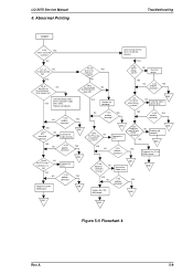
...correct printer driver. Is it OK ? NO Problem with a meter. Check printhead, motors drivers and power supply YES with computer. missing ? NO Are all NO the LEDs on the control panel blink at power on? Replace any wires in the YES printhead broken? Connect the cable correctly... EENNDD Figure 5-6 Flowchart 4 Rev.A 5-9 YES Replace the printhead.. YES NO Is the YES probelm corrected? Replace the C186 MAIN baord. LQ-2070 Service Manual 4. YES NO Is the YES problem corrected ? YES NO Replace the FFC. Is it OK? YES END YES NO Is the...
...correct printer driver. Is it OK ? NO Problem with a meter. Check printhead, motors drivers and power supply YES with computer. missing ? NO Are all NO the LEDs on the control panel blink at power on? Replace any wires in the YES printhead broken? Connect the cable correctly... EENNDD Figure 5-6 Flowchart 4 Rev.A 5-9 YES Replace the printhead.. YES NO Is the YES probelm corrected? Replace the C186 MAIN baord. LQ-2070 Service Manual 4. YES NO Is the YES problem corrected ? YES NO Replace the FFC. Is it OK? YES END YES NO Is the...

Service Manual
Page 147
...LQ-2070 Exploded Diagrams (1 A-20 Figure A-9. LQ-2070 Exploded Diagrams (2 A-21 Figure A-10. CSF Bin 1 Exploded Diagrams (2 A-24 Figure A-13. CN3 A-6 Table A-3. Connector Pin Assignments - Connector Pin Assignments - CN9 A-8 Table A-9. CN11 A-8 Table A-11. Connector Pin Assignments - Connector Pin Assignments - Appendix Table of Tables Table A-1. Cable Connections...Contents A.1. CN13 A-9 Table A-13. CN15 A-9 C186 MAIN Board Assembly Circuit Diagram A-11 Figure A-3. LQ-2070 Exploded Diagrams (3 A-22 Figure A-11. Connector Pin Assignments - CN10 A-8 Table A-10. C166 PSE...
...LQ-2070 Exploded Diagrams (1 A-20 Figure A-9. LQ-2070 Exploded Diagrams (2 A-21 Figure A-10. CSF Bin 1 Exploded Diagrams (2 A-24 Figure A-13. CN3 A-6 Table A-3. Connector Pin Assignments - Connector Pin Assignments - CN9 A-8 Table A-9. CN11 A-8 Table A-11. Connector Pin Assignments - Connector Pin Assignments - Appendix Table of Tables Table A-1. Cable Connections...Contents A.1. CN13 A-9 Table A-13. CN15 A-9 C186 MAIN Board Assembly Circuit Diagram A-11 Figure A-3. LQ-2070 Exploded Diagrams (3 A-22 Figure A-11. Connector Pin Assignments - CN10 A-8 Table A-10. C166 PSE...

Service Manual
Page 153
Cable Connections Rev.A A-5 Table A-1 summarizes functions and sizes of the connectors. LQ-2070 Service Manual Appendix A.3 CONNECTOR SUMMARY Figure A-1 illustrates how primary components are connected. Rear Sensor PE- Front Sensor HP Sensor PW Sensor Printhead Board Assy., C166 PSB / PSE Board Assy., C165PNL CN1 CSF Bin 1 CN15 CN8 CN7 CN4 CN6 CN5 CN12 CN13 CN11 CN10 CN3 CN9 CN16 CN1 CN14 Board Assy., C186 MAIN CN2 Host Computer Parallel I/F Option I/F Figure A-1. Printer Mechanism PF Motor CR Motor PG Sensor Release Lever Position Sensor PE-
Cable Connections Rev.A A-5 Table A-1 summarizes functions and sizes of the connectors. LQ-2070 Service Manual Appendix A.3 CONNECTOR SUMMARY Figure A-1 illustrates how primary components are connected. Rear Sensor PE- Front Sensor HP Sensor PW Sensor Printhead Board Assy., C166 PSB / PSE Board Assy., C165PNL CN1 CSF Bin 1 CN15 CN8 CN7 CN4 CN6 CN5 CN12 CN13 CN11 CN10 CN3 CN9 CN16 CN1 CN14 Board Assy., C186 MAIN CN2 Host Computer Parallel I/F Option I/F Figure A-1. Printer Mechanism PF Motor CR Motor PG Sensor Release Lever Position Sensor PE-


