Technical Brief (Impact Printers)
Page 1
..., or DFX Twenty-four pin printers all begin with LQ FX-980-Nine-pin narrow carriage Wide carriage printers have 4 number in their names Narrow carriage printers have 3 numbers in purchase price and low cost of their reliability with tireless printheads and superior quality ribbons. Impact printers are capable of Seiko Epson Corporation. 1/00 Other trademarks are...
..., or DFX Twenty-four pin printers all begin with LQ FX-980-Nine-pin narrow carriage Wide carriage printers have 4 number in their names Narrow carriage printers have 3 numbers in purchase price and low cost of their reliability with tireless printheads and superior quality ribbons. Impact printers are capable of Seiko Epson Corporation. 1/00 Other trademarks are...
User Manual
Page 109
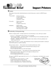
... to replace the ribbon. Maintenance and Transportation 5-3 Using any other printer parts. Printer model LQ-2070 Ribbon cartridge so15086 Ribbon pack so10033 To replace the ribbon cartridge, follow the steps in "Installing the Ribbon Cartridge" in the cartridge. Use the EPSON ribbon cartridge or pack listed below for 9 pin printers. A ribbon pack, containing ribbons only, is also available. Do not use a ribbon cartridge designed for...
... to replace the ribbon. Maintenance and Transportation 5-3 Using any other printer parts. Printer model LQ-2070 Ribbon cartridge so15086 Ribbon pack so10033 To replace the ribbon cartridge, follow the steps in "Installing the Ribbon Cartridge" in the cartridge. Use the EPSON ribbon cartridge or pack listed below for 9 pin printers. A ribbon pack, containing ribbons only, is also available. Do not use a ribbon cartridge designed for...
User Manual
Page 130
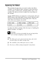
Mechanical Paper-feed methods: Ribbon life: Total print amount: Print head life: Friction feed (front and rear) Push tractor feed (rear:standard, front:with optional pull tractor C80032*) Push/Pull ... pull tractors C80032*) Pull tractor feed (front, rear, and bottom with optional pull tractor C80032*) Cut-sheet feeder (option C80673*, C80674*) 8 million characters (LQ 10 cpi, at 48 dots / character) 6 million lines (except print head) 200 million strokes/wire Specifications, Command Summary, and Character Tables A-9 The minimum right margin is 203.2 mm...
Mechanical Paper-feed methods: Ribbon life: Total print amount: Print head life: Friction feed (front and rear) Push tractor feed (rear:standard, front:with optional pull tractor C80032*) Push/Pull ... pull tractors C80032*) Pull tractor feed (front, rear, and bottom with optional pull tractor C80032*) Cut-sheet feeder (option C80673*, C80674*) 8 million characters (LQ 10 cpi, at 48 dots / character) 6 million lines (except print head) 200 million strokes/wire Specifications, Command Summary, and Character Tables A-9 The minimum right margin is 203.2 mm...
Service Manual
Page 10
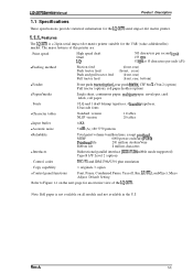
..., multipart paper, envelopes, card labels, roll paper . Control codes ESC/P2 and IBM 2390/2391 plus emulation . Features The LQ-2070 is not available on all models and not available in the U.S. Rev.A 1-1 Copy capability 1 original+ 3 copies q Control panel... million strokes/wire Ribbon life 8 million characters q Interfaces Bidirectional parallel interface (IEEE-P1284 nibble mode supported) Type B I/F Level 2 (option) . Note: Roll paper is a 24pin serial impact dot-matrix printer suitable for an exterior view of this printer are: . LQ-2070 Sendce Manual Product ...
..., multipart paper, envelopes, card labels, roll paper . Control codes ESC/P2 and IBM 2390/2391 plus emulation . Features The LQ-2070 is not available on all models and not available in the U.S. Rev.A 1-1 Copy capability 1 original+ 3 copies q Control panel... million strokes/wire Ribbon life 8 million characters q Interfaces Bidirectional parallel interface (IEEE-P1284 nibble mode supported) Type B I/F Level 2 (option) . Note: Roll paper is a 24pin serial impact dot-matrix printer suitable for an exterior view of this printer are: . LQ-2070 Sendce Manual Product ...
Service Manual
Page 25
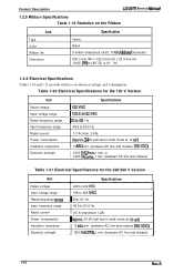
Product Description LQ-2070 Service Manuai 1.2.5 Ribbon Specifications Table 1-19 Statistics on the Ribbon Item Type Color Ribbon life Dimension Specification Fabric Black 8 million characters (draft, 10 cpi, 48dotcJ character) 506.0 mm (W) x 123.5 mm (D) x 23.0 mm (H) 19.92" (W) X 4.86" (D) X .91 " (H) 1.2.6 Electrical Specifications Tables 1-...
Product Description LQ-2070 Service Manuai 1.2.5 Ribbon Specifications Table 1-19 Statistics on the Ribbon Item Type Color Ribbon life Dimension Specification Fabric Black 8 million characters (draft, 10 cpi, 48dotcJ character) 506.0 mm (W) x 123.5 mm (D) x 23.0 mm (H) 19.92" (W) X 4.86" (D) X .91 " (H) 1.2.6 Electrical Specifications Tables 1-...
Service Manual
Page 26
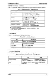
LQ-2070 Service Manual Product Description 1.2.7 Environmental Conditions Table 1-22 explains the conditions the printer requires during operation and when not operating, Table 1-22 Environmental Requirements Item I Ribbon life 8 million characters 1.2.9 Safety Approvals Table 1-24 provides information about the safety approvals the printer has met. Table 1-23 ... 15 subpart B class B EN55022 (CISPR pub.22) CSA CI08.8 class B Rev.A 1-17 Table 1-24 Safety Information for Printer Models Safety Standards EMI 120 v I 230 V UL1950 with D3 CSA C22.2 N0,950 with D3 EN60950 (TuV.
LQ-2070 Service Manual Product Description 1.2.7 Environmental Conditions Table 1-22 explains the conditions the printer requires during operation and when not operating, Table 1-22 Environmental Requirements Item I Ribbon life 8 million characters 1.2.9 Safety Approvals Table 1-24 provides information about the safety approvals the printer has met. Table 1-23 ... 15 subpart B class B EN55022 (CISPR pub.22) CSA CI08.8 class B Rev.A 1-17 Table 1-24 Safety Information for Printer Models Safety Standards EMI 120 v I 230 V UL1950 with D3 CSA C22.2 N0,950 with D3 EN60950 (TuV.
Service Manual
Page 49
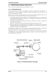
... used for head temperature detection. Wire Resetting Spring Ribbon Stopper Dot Wire Ribbon Mask Paper Actuating Plate Iron Core Head Driving Coil Actuating Spring Platen Figure 2-1 Printhead Operation Principles Rev.A 2-1 LQ-2070 Service Manual Operating Principles 2.1 PRINTER MECHANISM OPERATION This section describes the printer mechanism and explains how it prints a dot. 4. A drive signal, transmitted from the iron core...
... used for head temperature detection. Wire Resetting Spring Ribbon Stopper Dot Wire Ribbon Mask Paper Actuating Plate Iron Core Head Driving Coil Actuating Spring Platen Figure 2-1 Printhead Operation Principles Rev.A 2-1 LQ-2070 Service Manual Operating Principles 2.1 PRINTER MECHANISM OPERATION This section describes the printer mechanism and explains how it prints a dot. 4. A drive signal, transmitted from the iron core...

Service Manual
Page 64
... in the gear linkage. Operation Principles LQ-2070 Servcie Manual 2.1.6 Ribbon Advance Mechanism The ribbon is transmitted to the ribbon driving gear through the gear trains. Then the torque is held between the ribbon advance roller (ribbon driven gear) and the ribbon pressure roller. Figure 2-21 Ribbon Advance Mechanism 2-16 Rev.A Table 2-4. Ribbon Advance Gear Linkage Direction of Carriage Movement...
... in the gear linkage. Operation Principles LQ-2070 Servcie Manual 2.1.6 Ribbon Advance Mechanism The ribbon is transmitted to the ribbon driving gear through the gear trains. Then the torque is held between the ribbon advance roller (ribbon driven gear) and the ribbon pressure roller. Figure 2-21 Ribbon Advance Mechanism 2-16 Rev.A Table 2-4. Ribbon Advance Gear Linkage Direction of Carriage Movement...
Service Manual
Page 80
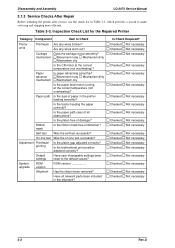
...the CR motor at the correct temperature (not overheating)? Is the type of all relevant parts been included in the shipment? Ribbon mask Self-test Is the platen free of distortion? On-line test Was the on-line test successful? System upgrade ROM ...version ROM version ________. Disassembly and Assembly LQ-2070 Service Manual 3.1.3 Service Checks After Repair Before returning the printer after service, use the check list in the printer feeding smoothly? Carriage Does the carriage move smoothly? Was the self-test successful?...
...the CR motor at the correct temperature (not overheating)? Is the type of all relevant parts been included in the shipment? Ribbon mask Self-test Is the platen free of distortion? On-line test Was the on-line test successful? System upgrade ROM ...version ROM version ________. Disassembly and Assembly LQ-2070 Service Manual 3.1.3 Service Checks After Repair Before returning the printer after service, use the check list in the printer feeding smoothly? Carriage Does the carriage move smoothly? Was the self-test successful?...

Service Manual
Page 82
...you how the components fit together. PG adjustment required. Also disconnect the interface cable. • Whenever the printer is replaced). Bidirectional adjustment and factory setting required (when part is repaired, wipe the surface of the paper... (PW) sensor assembly with a soft cloth, and keep it clean to disassemble the printer, remove the paper and the ink ribbon. If necessary, special notes on assembling or adjusting a component are given at the end... not describe the assembly procedure. Disassembly and Assembly LQ-2070 Service Manual 3.2. Be sure to them as necessary.
...you how the components fit together. PG adjustment required. Also disconnect the interface cable. • Whenever the printer is replaced). Bidirectional adjustment and factory setting required (when part is repaired, wipe the surface of the paper... (PW) sensor assembly with a soft cloth, and keep it clean to disassemble the printer, remove the paper and the ink ribbon. If necessary, special notes on assembling or adjusting a component are given at the end... not describe the assembly procedure. Disassembly and Assembly LQ-2070 Service Manual 3.2. Be sure to them as necessary.

Service Manual
Page 83
Rev.A 3-5 LQ-2070 Service Manual Disassembly and Assembly 3.2.1. When remounting them, be sure to release the hooks at both sides. Remove the following parts: È Front edge guide assembly ‘ Front cover Ç Rear edge guide assembly • Printer cover . Front/rear tractor assembly ° Ribbon cartridge Refer to the following figure. ’ Bottom...
Rev.A 3-5 LQ-2070 Service Manual Disassembly and Assembly 3.2.1. When remounting them, be sure to release the hooks at both sides. Remove the following parts: È Front edge guide assembly ‘ Front cover Ç Rear edge guide assembly • Printer cover . Front/rear tractor assembly ° Ribbon cartridge Refer to the following figure. ’ Bottom...

Service Manual
Page 84
... C165 PNL board assembly. 4. The FFC must be connected properly, as shown in Figure 3-5. Removing the Panel Board Assembly 1. Remove the printer cover and ribbon cartridge (see Section 3.2.1). 2. Disassembly and Assembly LQ-2070 Service Manual 3.2.2. CN1 Figure 3-4 Removing the Panel Board Assembly Assembly Notes Lock Cover for CN 1 CN 1 Slide CN 1 CN 1 FFC Exposed...
... C165 PNL board assembly. 4. The FFC must be connected properly, as shown in Figure 3-5. Removing the Panel Board Assembly 1. Remove the printer cover and ribbon cartridge (see Section 3.2.1). 2. Disassembly and Assembly LQ-2070 Service Manual 3.2.2. CN1 Figure 3-4 Removing the Panel Board Assembly Assembly Notes Lock Cover for CN 1 CN 1 Slide CN 1 CN 1 FFC Exposed...

Service Manual
Page 85
Remove the printhead from the connector on the CR cover. cm ) Adjust the platen gap. Remove the printer cover and ribbon cartridge (see Section 3.2.1). 2. Disconnect 2 wide FFCs from the printhead and then disconnect the narrow FFC from the CR assembly. 4.... Refer to the CR assembly. 3. Figure 3-7 Method for the 2 CBS screws (3 × 10, F/Zn) = 0.59 ~ 0.78 Nm ( 6 ~8 Kg f. LQ-2070 Service Manual Disassembly and Assembly 3.2.3....
Remove the printhead from the connector on the CR cover. cm ) Adjust the platen gap. Remove the printer cover and ribbon cartridge (see Section 3.2.1). 2. Disconnect 2 wide FFCs from the printhead and then disconnect the narrow FFC from the CR assembly. 4.... Refer to the CR assembly. 3. Figure 3-7 Method for the 2 CBS screws (3 × 10, F/Zn) = 0.59 ~ 0.78 Nm ( 6 ~8 Kg f. LQ-2070 Service Manual Disassembly and Assembly 3.2.3....

Service Manual
Page 86
...for the HP sensor. 3. Remove the CB screw (2.5 × 5, F/Zn) securing the PW sensor to the ribbon mask holder. Figure 3-9 Removing the PW Sensor Assembly 3-8 Rev.A Remove the printer cover, ribbon cartridge, front edge guide, and front cover (see Section 3.2.1). 2. Then, remove the FFC from the front paper ... HP Sensor Assembly Note Notice the direction for mounting the HP sensor. 3.2.5 Removing the PW Sensor Assembly 1. Remove the printer cover and ribbon cartridge (see Section 3.2.1). 2. Disassembly and Assembly LQ-2070 Service Manual 3.2.4 Removing the HP Sensor 1.
...for the HP sensor. 3. Remove the CB screw (2.5 × 5, F/Zn) securing the PW sensor to the ribbon mask holder. Figure 3-9 Removing the PW Sensor Assembly 3-8 Rev.A Remove the printer cover, ribbon cartridge, front edge guide, and front cover (see Section 3.2.1). 2. Then, remove the FFC from the front paper ... HP Sensor Assembly Note Notice the direction for mounting the HP sensor. 3.2.5 Removing the PW Sensor Assembly 1. Remove the printer cover and ribbon cartridge (see Section 3.2.1). 2. Disassembly and Assembly LQ-2070 Service Manual 3.2.4 Removing the HP Sensor 1.

Service Manual
Page 87
... Perforated line is not clean, abnormal operations may occur, such as printing on the platen surface. LQ-2070 Service Manual Disassembly and Assembly Assembly Notes Mount the PW sensor assembly onto the ribbon mask holder groove, aligning the bottom line of micro photo sensor to Chapter 4. If the surface ...is the Groove. Refer to the bottom line of PW Sensor through Ribbon Mask Holder Ribbon Mask Holder Figure 3-10 Mounting Position for the CB screw (2.5 × 5, F/Zn) = 0.08 ~ 0.12 Nm (0.8 ~ 0.12 Kg f-cm) When you ...
... Perforated line is not clean, abnormal operations may occur, such as printing on the platen surface. LQ-2070 Service Manual Disassembly and Assembly Assembly Notes Mount the PW sensor assembly onto the ribbon mask holder groove, aligning the bottom line of micro photo sensor to Chapter 4. If the surface ...is the Groove. Refer to the bottom line of PW Sensor through Ribbon Mask Holder Ribbon Mask Holder Figure 3-10 Mounting Position for the CB screw (2.5 × 5, F/Zn) = 0.08 ~ 0.12 Nm (0.8 ~ 0.12 Kg f-cm) When you ...

Service Manual
Page 88
Disassembly and Assembly LQ-2070 Service Manual 3.2.6 Removing the Platen Assembly 1. Release both locks for the left edge of the platen assembly upward by pushing the lever holder for the ...-assembly operation helps you mount the platen assembly more easily. Figure 3-12 Removing the Platen Assembly Assembly Notes Before reinstalling the platen assembly into the printer mechanism, make sure both locks for the left and right bushings (8 mm) are fragile. After installing the platen assembly into the...
Disassembly and Assembly LQ-2070 Service Manual 3.2.6 Removing the Platen Assembly 1. Release both locks for the left edge of the platen assembly upward by pushing the lever holder for the ...-assembly operation helps you mount the platen assembly more easily. Figure 3-12 Removing the Platen Assembly Assembly Notes Before reinstalling the platen assembly into the printer mechanism, make sure both locks for the left and right bushings (8 mm) are fragile. After installing the platen assembly into the...
Service Manual
Page 98
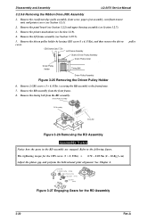
Remove the printer mechanism (see Section 3.2.7). 3. Remove the driven pulley holder by loosing CBS screw(3 x 6, F/Zn), and then remove the driven cover. Remove the RD assembly from the ... platen gap and perform the bidirectional print alignment. Remove the rear/front edge guide assembly, front cover, paper eject assembly, rear/front tractor unit, and printer cover (see Section 3.2.9.5). 5. Disassembly and Assembly LQ-2070 Service Manual 3.2.9.6 Removing the Ribbon Drive (RD) Assembly 1.
Remove the printer mechanism (see Section 3.2.7). 3. Remove the driven pulley holder by loosing CBS screw(3 x 6, F/Zn), and then remove the driven cover. Remove the RD assembly from the ... platen gap and perform the bidirectional print alignment. Remove the rear/front edge guide assembly, front cover, paper eject assembly, rear/front tractor unit, and printer cover (see Section 3.2.9.5). 5. Disassembly and Assembly LQ-2070 Service Manual 3.2.9.6 Removing the Ribbon Drive (RD) Assembly 1.

Service Manual
Page 115
... Slot Figure 4-2 Setting the PG Adjust Lever 8. Insert the thickness gauge vertically between the printhead and platen. 4-2 Rev.A Ribbon Mask Ribbon Mask Holder Figure 4-1 Removing the Ribbon Mask 3. Adjustment LQ-2070 Service Manual 4.2 ADJUSTING AND RESETTING THE PRINTER 4.2.1 Platen Gap Adjustment If you have rotated or reassembled the rear CR guide shaft or parallelism adjustment bushing...
... Slot Figure 4-2 Setting the PG Adjust Lever 8. Insert the thickness gauge vertically between the printhead and platen. 4-2 Rev.A Ribbon Mask Ribbon Mask Holder Figure 4-1 Removing the Ribbon Mask 3. Adjustment LQ-2070 Service Manual 4.2 ADJUSTING AND RESETTING THE PRINTER 4.2.1 Platen Gap Adjustment If you have rotated or reassembled the rear CR guide shaft or parallelism adjustment bushing...

Service Manual
Page 116
.... Tighten the hexagon nut (standard, M4) securing the PG adjust lever. After inserting the ribbon mask in the ribbon mask holder and installing the printhead into the drilled hole at the 80th, and then the 130th column positions. LQ-2070 Service Manual Adjustment 9. Figure 4-4 Adjusting the Parallelism of the CR guide shaft by moving...
.... Tighten the hexagon nut (standard, M4) securing the PG adjust lever. After inserting the ribbon mask in the ribbon mask holder and installing the printhead into the drilled hole at the 80th, and then the 130th column positions. LQ-2070 Service Manual Adjustment 9. Figure 4-4 Adjusting the Parallelism of the CR guide shaft by moving...
Service Manual
Page 131
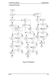
LQ-2070 Service Manual 4. YES Do all NO the dosts printed OK? ... supply YES with computer. NO Dose the resistence NO of NO Reinstall the END characters Ribbon mask. END NO Install the correct printer driver. Connect the cable correctly. YES Is the YES probelm corrected? NO Are all ...NO the LEDs on the control panel blink at power on? Reset the printer. Are the correct printer drivers installed ? YES NO Is the YES problem corrected ? missing ? EENNDD EEENNNDDD EENNDD Figure 5-6 Flowchart ...
LQ-2070 Service Manual 4. YES Do all NO the dosts printed OK? ... supply YES with computer. NO Dose the resistence NO of NO Reinstall the END characters Ribbon mask. END NO Install the correct printer driver. Connect the cable correctly. YES Is the YES probelm corrected? NO Are all ...NO the LEDs on the control panel blink at power on? Reset the printer. Are the correct printer drivers installed ? YES NO Is the YES problem corrected ? missing ? EENNDD EEENNNDDD EENNDD Figure 5-6 Flowchart ...


