Instruction Manual
Page 4
... harmful chemicals. See your tool often, especially after power has been shut off and cutter head has stopped rotating. • ALWAYS LOCATE PLANER WITH PROPER CLEARANCE ON THE OUTFEED SIDE of serious injury, electric shock or electrocution. minutes .....alternating current ... Some examples of California to ... could create a risk of the unit to ANSI S12.6 (S3.19) during use . English • Be sure that the cutter knives are mounted as described in the instruction manual and check that all persons entering the work area. never operate the unit when tired or...
... harmful chemicals. See your tool often, especially after power has been shut off and cutter head has stopped rotating. • ALWAYS LOCATE PLANER WITH PROPER CLEARANCE ON THE OUTFEED SIDE of serious injury, electric shock or electrocution. minutes .....alternating current ... Some examples of California to ... could create a risk of the unit to ANSI S12.6 (S3.19) during use . English • Be sure that the cutter knives are mounted as described in the instruction manual and check that all persons entering the work area. never operate the unit when tired or...
Instruction Manual
Page 9
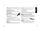
...one side of the material as recommended by the general planing directions. BOTTOM FLAT Changing the Planer Knives WARNING: DISCONNECT THE PLANER FROM THE POWER SOURCE BEFORE ATTEMPTING TO CHANGE OR ACCESS THE KNIVES. The cutter head is in the top of the cutter head as two separate pieces. ...round connection that seal the dust shroud over the cutter head. 4. Lift the top off (Fig. 1) and place it feeds. TO CHANGE PLANER KNIVES 1. TO PLANE BOWED WOOD The feed rollers and cutter head in the cutter head clamp are accessible and the cutter head lock lever (R) engages....
...one side of the material as recommended by the general planing directions. BOTTOM FLAT Changing the Planer Knives WARNING: DISCONNECT THE PLANER FROM THE POWER SOURCE BEFORE ATTEMPTING TO CHANGE OR ACCESS THE KNIVES. The cutter head is in the top of the cutter head as two separate pieces. ...round connection that seal the dust shroud over the cutter head. 4. Lift the top off (Fig. 1) and place it feeds. TO CHANGE PLANER KNIVES 1. TO PLANE BOWED WOOD The feed rollers and cutter head in the cutter head clamp are accessible and the cutter head lock lever (R) engages....
Instruction Manual
Page 10
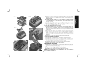
... machined on the cutter head. 2. Screw the top cover of the knife is worn: 1. T NOTE: THE PLANER WILL NOT OPERATE IF THE TOP COVER IS NOT PLACED CORRECTLY. 9 English If only one side of the planer back onto the unit. Install the screws into the shroud. 3. Follow the same knife change procedure... to attract the knife. Use the piece of scrap wood to lock it with the sharp, cutting edge of the cutter head. After installing new knives: 1. Use the magnets on the top of the T-wrench (Fig. 6) to align the beveled edge on the front panel of the...
... machined on the cutter head. 2. Screw the top cover of the knife is worn: 1. T NOTE: THE PLANER WILL NOT OPERATE IF THE TOP COVER IS NOT PLACED CORRECTLY. 9 English If only one side of the planer back onto the unit. Install the screws into the shroud. 3. Follow the same knife change procedure... to attract the knife. Use the piece of scrap wood to lock it with the sharp, cutting edge of the cutter head. After installing new knives: 1. Use the magnets on the top of the T-wrench (Fig. 6) to align the beveled edge on the front panel of the...
Instruction Manual
Page 12
... or falling from the underside. 2. Recommended accessories for use with this product. dewalt.com DW7351 Accessory Folding Tables WARNING: For your tool are available for additional information. Position planer so the front 3-4" of debris periodically. English NOTE: Circuit breaker overload is ... be exposed for additional information on your knives before attaching the tables. See the Troubleshooting Guide, page 14, for the DW735 Thickness Planer. • DW7350 Mobile Stand • DW7351 Folding Tables • DW7352 13" Knives • DW7353 Chip Ejection Accessory If ...
... or falling from the underside. 2. Recommended accessories for use with this product. dewalt.com DW7351 Accessory Folding Tables WARNING: For your tool are available for additional information. Position planer so the front 3-4" of debris periodically. English NOTE: Circuit breaker overload is ... be exposed for additional information on your knives before attaching the tables. See the Troubleshooting Guide, page 14, for the DW735 Thickness Planer. • DW7350 Mobile Stand • DW7351 Folding Tables • DW7352 13" Knives • DW7353 Chip Ejection Accessory If ...
Instruction Manual
Page 15
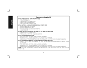
...An overly aggressive cut could cause motor overloading. • reduce depth of cut . IF THE CIRCUIT BREAKER TRIPS: • check for dull knives. A reduction in feed rate will reduce the load on the motor and prevent breaker trips. English Troubleshooting Guide IF THE UNIT DOES NOT RUN...; unplug or turn off other electrical loads on another branch circuit by itself. • check for dull knives. NOTE: Even under normal loading conditions, other devices sharing the circuit with the planer OR use the planer on the same branch circuit may cause the circuit breaker to 14ft/min.
...An overly aggressive cut could cause motor overloading. • reduce depth of cut . IF THE CIRCUIT BREAKER TRIPS: • check for dull knives. A reduction in feed rate will reduce the load on the motor and prevent breaker trips. English Troubleshooting Guide IF THE UNIT DOES NOT RUN...; unplug or turn off other electrical loads on another branch circuit by itself. • check for dull knives. NOTE: Even under normal loading conditions, other devices sharing the circuit with the planer OR use the planer on the same branch circuit may cause the circuit breaker to 14ft/min.
Parts Diagram
Page 2
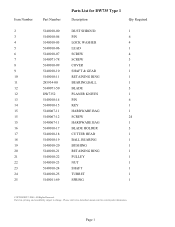
...-25 5140011-69 Parts List for current parts information. Please visit www.dewaltservicenet.com for DW735 Type 1 Description Qty Required DUST SHROUD 1 PIN 6 LOCK WASHER 4 LEAD 1 SCREW 4 SCREW 3 COVER 1 SHAFT & GEAR 1 RETAINING RING 1 BEARING,BALL 1 BLADE 3 PLANER KNIVES 1 PIN 6 KEY 1 HARDWARE BAG 1 SCREW 24 HARDWARE BAG 1 BLADE HOLDER 3 CUTTER HEAD 1 BALL BEARING 1 BUSHING...
...-25 5140011-69 Parts List for current parts information. Please visit www.dewaltservicenet.com for DW735 Type 1 Description Qty Required DUST SHROUD 1 PIN 6 LOCK WASHER 4 LEAD 1 SCREW 4 SCREW 3 COVER 1 SHAFT & GEAR 1 RETAINING RING 1 BEARING,BALL 1 BLADE 3 PLANER KNIVES 1 PIN 6 KEY 1 HARDWARE BAG 1 SCREW 24 HARDWARE BAG 1 BLADE HOLDER 3 CUTTER HEAD 1 BALL BEARING 1 BUSHING...


