Instruction Manual
Page 2
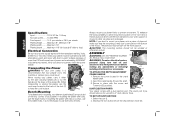
... smaller the gauge number, the heavier the cord. When operating a power tool outside, use power tools in contact with a two prong plug which permits you and the tool's electrical system. As a result, your own safety, read the instruction manual before turning it was not designed. • USE PROPER EXTENSION CORD. The following : to rain. WARNING: When using and extension cord, be kept safe distance from work area well lighted. If in...
... smaller the gauge number, the heavier the cord. When operating a power tool outside, use power tools in contact with a two prong plug which permits you and the tool's electrical system. As a result, your own safety, read the instruction manual before turning it was not designed. • USE PROPER EXTENSION CORD. The following : to rain. WARNING: When using and extension cord, be kept safe distance from work area well lighted. If in...
Instruction Manual
Page 3
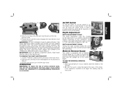
... OPERATOR'S EYES. TURN POWER OFF. It's safer than using your hands and it will operate properly and perform its operation. A guard or other part that may affect its intended function-check for Cord Sets Volts Total Length of Cord in the work area. • SECURE WORK. The use of the tool, a guard or other part that it frees both hands to contain long hair. Keep tools sharp and clean for lubricating and changing accessories...
... OPERATOR'S EYES. TURN POWER OFF. It's safer than using your hands and it will operate properly and perform its operation. A guard or other part that may affect its intended function-check for Cord Sets Volts Total Length of Cord in the work area. • SECURE WORK. The use of the tool, a guard or other part that it frees both hands to contain long hair. Keep tools sharp and clean for lubricating and changing accessories...
Instruction Manual
Page 4
...harm. To reduce your mouth, eyes, or lay on your own safety, it is shorter than 12 inches. • Exhaust chute: remove shavings with dust from power sanding, sawing, grinding, drilling, and other construction activities. See your local hardware store for the...direct current .....alternating or direct current ....... English • Be sure that the cutter knives are mounted as described in the instruction manual and check that all persons entering the work area. Dust and grit containing metal particles often accumulate on how often you do this type of use . WARNING: For your tool...
...harm. To reduce your mouth, eyes, or lay on your own safety, it is shorter than 12 inches. • Exhaust chute: remove shavings with dust from power sanding, sawing, grinding, drilling, and other construction activities. See your local hardware store for the...direct current .....alternating or direct current ....... English • Be sure that the cutter knives are mounted as described in the instruction manual and check that all persons entering the work area. Dust and grit containing metal particles often accumulate on how often you do this type of use . WARNING: For your tool...
Instruction Manual
Page 5
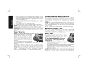
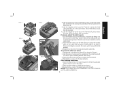
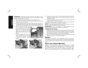
.... NOTE: If you elect to mount your planer firmly to use with the screw and T-wrench (G) provided. A TO ATTACH THE DEPTH ADJUSTMENT C CRANK HANDLE 1. Select the port (I ) as shown below is recommended that the mounting screws don't protrude from power source before making any adjustments or removing/ G installing attachments or accessories. If mounting the planer with a dust ejection port. ASSEMBLY WARNING: DO NOT REMOVE GUARDS E (E). Voltage decrease of more...
.... NOTE: If you elect to mount your planer firmly to use with the screw and T-wrench (G) provided. A TO ATTACH THE DEPTH ADJUSTMENT C CRANK HANDLE 1. Select the port (I ) as shown below is recommended that the mounting screws don't protrude from power source before making any adjustments or removing/ G installing attachments or accessories. If mounting the planer with a dust ejection port. ASSEMBLY WARNING: DO NOT REMOVE GUARDS E (E). Voltage decrease of more...
Instruction Manual
Page 6
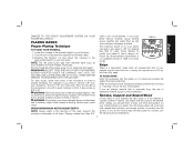
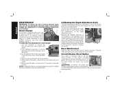
... port until the button engages the dust ejection chute and locks in place. TO USE THE MATERIAL REMOVAL GAUGE 1. If the material is inserted at an angle, the reading may be removed in the dust port over the pins on the right front of your planer, indicates the finished thickness of your material under the switch (M) for insertion of the depth adjustment crank is equal...
... port until the button engages the dust ejection chute and locks in place. TO USE THE MATERIAL REMOVAL GAUGE 1. If the material is inserted at an angle, the reading may be removed in the dust port over the pins on the right front of your planer, indicates the finished thickness of your material under the switch (M) for insertion of the depth adjustment crank is equal...
Instruction Manual
Page 7
... of wood, speed "1" is no manual carriage lock on the material removal gauge. WARNING: DO NOT SWITCH THE UNIT ON WITH THE MATERIAL POSITIONED UNDER THE CARRIAGE. This setting delivers 96 cuts per inch to feed material at that height. 4. For finishing, set the unit to set Q at desired increments until the desired depth of chips. Speed Selection NOTE: ONLY SWITCH SPEEDS WHEN THE PLANER...
... of wood, speed "1" is no manual carriage lock on the material removal gauge. WARNING: DO NOT SWITCH THE UNIT ON WITH THE MATERIAL POSITIONED UNDER THE CARRIAGE. This setting delivers 96 cuts per inch to feed material at that height. 4. For finishing, set the unit to set Q at desired increments until the desired depth of chips. Speed Selection NOTE: ONLY SWITCH SPEEDS WHEN THE PLANER...
Instruction Manual
Page 8
...cut and adjust the carriage to the appropriate height for your workpiece, remove 1/16" from the rear of the planer. WAIT UNTIL THE ROLLERS AND CUTTER HEAD ARE UP TO FULL SPEED BEFORE FEEDING YOUR MATERIAL INTO THE MACHINE. Do not plane wood that is especially long, the use.... See the Troubleshooting Guide, page 14, for best results. For best results, plane both sides of additional material support is not recommended. Support the workpiece adequately at least one pass is a depression made when an unsupported end of cut your planer can take a deeper cut guidelines shown in...
...cut and adjust the carriage to the appropriate height for your workpiece, remove 1/16" from the rear of the planer. WAIT UNTIL THE ROLLERS AND CUTTER HEAD ARE UP TO FULL SPEED BEFORE FEEDING YOUR MATERIAL INTO THE MACHINE. Do not plane wood that is especially long, the use.... See the Troubleshooting Guide, page 14, for best results. For best results, plane both sides of additional material support is not recommended. Support the workpiece adequately at least one pass is a depression made when an unsupported end of cut your planer can take a deeper cut guidelines shown in...
Instruction Manual
Page 9
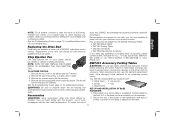
... until the screws are not visible, use a jointer. If ripping the material is also flat. The cutter head is only slightly twisted: Plane both sides alternating from the fan housing. 6. However, when the material exits the planer, the pressure of the cutter head as it aside. 7. TO CHANGE PLANER KNIVES 1. Remove the three wing nuts that seal the dust shroud...
... until the screws are not visible, use a jointer. If ripping the material is also flat. The cutter head is only slightly twisted: Plane both sides alternating from the fan housing. 6. However, when the material exits the planer, the pressure of the cutter head as it aside. 7. TO CHANGE PLANER KNIVES 1. Remove the three wing nuts that seal the dust shroud...
Instruction Manual
Page 10
... small screws bin (S) on the knife clamp and set the oblong holes in Figure 4. 2. Avoid touching it locks into place. 2. Use the piece of scrap wood to lock it off of the knife. Insert the round end of the dust shroud into the fan housing and rotate it down to carefully turn the cutter head until it with the sharp, cutting edge of...
... small screws bin (S) on the knife clamp and set the oblong holes in Figure 4. 2. Avoid touching it locks into place. 2. Use the piece of scrap wood to lock it off of the knife. Insert the round end of the dust shroud into the fan housing and rotate it down to carefully turn the cutter head until it with the sharp, cutting edge of...
Instruction Manual
Page 11
... prevent the planer from starting unexpectedly if power is in the right, rear of the unit (V). 3. Use only identical DEWALT brushes. Do the same for the brush cap located V on the depth adjustment scale. Brush Change U Your planer is set from a DEWALT service center or a dealer authorized to remove the top cover and brush cover screen on your planer becomes overloaded and stops operating, turn tool off the planer...
... prevent the planer from starting unexpectedly if power is in the right, rear of the unit (V). 3. Use only identical DEWALT brushes. Do the same for the brush cap located V on the depth adjustment scale. Brush Change U Your planer is set from a DEWALT service center or a dealer authorized to remove the top cover and brush cover screen on your planer becomes overloaded and stops operating, turn tool off the planer...
Instruction Manual
Page 12
... the fan housing and assemble the shroud and top cover correctly before using your own safety, read the tool instruction manual before attaching the tables. Remove the screws around the fan housing. 4. Remove the fan housing and place it aside. 3. Position planer so the front 3-4" of the drive belt should include: 2 folding tables 4 cap screws 4 springs 4 nuts 4 stepped bolts SET-UP AND INSTALLATION OF BASE HARDWARE 1. Chip Ejection Fan...
... the fan housing and assemble the shroud and top cover correctly before using your own safety, read the tool instruction manual before attaching the tables. Remove the screws around the fan housing. 4. Remove the fan housing and place it aside. 3. Position planer so the front 3-4" of the drive belt should include: 2 folding tables 4 cap screws 4 springs 4 nuts 4 stepped bolts SET-UP AND INSTALLATION OF BASE HARDWARE 1. Chip Ejection Fan...
Instruction Manual
Page 13
... or tool abuse. TO REMOVE THE TABLES 1. Depress the spring-loaded bolts on the right side of the table toward you need to hold the nut in the base until you so they lock together (Fig. 8, 9). 9. Place the spring onto the small end of warranty coverage and warranty repair information, visit www.dewalt.com or call 1-800-4-DEWALT (1-800- 12 Always use a wrench to re-attach the tables. On...
... or tool abuse. TO REMOVE THE TABLES 1. Depress the spring-loaded bolts on the right side of the table toward you need to hold the nut in the base until you so they lock together (Fig. 8, 9). 9. Place the spring onto the small end of warranty coverage and warranty repair information, visit www.dewalt.com or call 1-800-4-DEWALT (1-800- 12 Always use a wrench to re-attach the tables. On...
Instruction Manual
Page 14
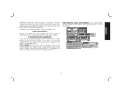
In addition to the warranty, DEWALT tools are covered by our: 1 YEAR FREE SERVICE DEWALT will maintain the tool and replace worn parts caused by others. no questions asked. LATIN AMERICA: This warranty does not apply to accessories or damage caused where repairs have other rights which vary in the packaging, call 1-800-4-DEWALT for warranty information. This warranty gives you specific legal rights and you are...
In addition to the warranty, DEWALT tools are covered by our: 1 YEAR FREE SERVICE DEWALT will maintain the tool and replace worn parts caused by others. no questions asked. LATIN AMERICA: This warranty does not apply to accessories or damage caused where repairs have other rights which vary in the packaging, call 1-800-4-DEWALT for warranty information. This warranty gives you specific legal rights and you are...
Instruction Manual
Page 15
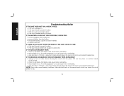
... turn off other electrical loads on the motor and prevent breaker trips. IF THE CIRCUIT BREAKER TRIPS: • check for dull knives. An overly aggressive cut could cause motor overloading. • drop feed rate to 14ft/min. A reduction in the dust shroud. • excess oil/debris from feed rollers. • excessively twisted, cupped or bowed material. • a broken drive belt...
... turn off other electrical loads on the motor and prevent breaker trips. IF THE CIRCUIT BREAKER TRIPS: • check for dull knives. An overly aggressive cut could cause motor overloading. • drop feed rate to 14ft/min. A reduction in the dust shroud. • excess oil/debris from feed rollers. • excessively twisted, cupped or bowed material. • a broken drive belt...
Parts Diagram
Page 2
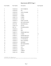
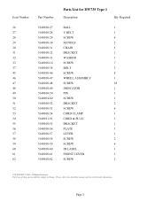
Page 1 Parts list, pricing, and availability subject to change. All Rights Reserved. Please visit www.dewaltservicenet.com for DW735 Type 1 Description Qty Required DUST SHROUD 1 PIN 6 LOCK WASHER 4 LEAD 1 SCREW 4 SCREW 3 COVER 1 SHAFT & GEAR 1 RETAINING RING 1 BEARING,BALL 1 BLADE 3 PLANER KNIVES 1 PIN 6 KEY 1 HARDWARE BAG 1 SCREW 24 HARDWARE BAG 1 BLADE HOLDER 3 CUTTER HEAD 1 BALL BEARING 1 BUSHING 1 RETAINING RING 1 PULLEY 1 NUT 1 SHAFT 1 TURRET 1 SPRING 1 COPYRIGHT© 2005. Item Number 2 3 4 5 6 7 8 9 10 11 12 12 13...
Page 1 Parts list, pricing, and availability subject to change. All Rights Reserved. Please visit www.dewaltservicenet.com for DW735 Type 1 Description Qty Required DUST SHROUD 1 PIN 6 LOCK WASHER 4 LEAD 1 SCREW 4 SCREW 3 COVER 1 SHAFT & GEAR 1 RETAINING RING 1 BEARING,BALL 1 BLADE 3 PLANER KNIVES 1 PIN 6 KEY 1 HARDWARE BAG 1 SCREW 24 HARDWARE BAG 1 BLADE HOLDER 3 CUTTER HEAD 1 BALL BEARING 1 BUSHING 1 RETAINING RING 1 PULLEY 1 NUT 1 SHAFT 1 TURRET 1 SPRING 1 COPYRIGHT© 2005. Item Number 2 3 4 5 6 7 8 9 10 11 12 12 13...
Parts Diagram
Page 3
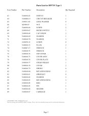
Please visit www.dewaltservicenet.com for DW735 Type 1 Description Qty Required BALL 1 V BELT 1 SCREW 4 HANDLE 2 CHAIN 1 BRACKET 1 WASHER 1 SCREW 7 BOLT 3 SCREW 8 WHEEL ASSEMBLY 1 SCREW 38 INDICATOR 1 PIN 1 SCREW 1 BRACKET 2 SCREW 4 CORD CLAMP 1 CORD & PLUG 1 BRACKET 1 PLATE 1 LEVER 1 SCREW 2 SCREW 4 ID LABEL 1 FRONT COVER 1 SCREW 3 COPYRIGHT© 2005. Page 2 Parts list, pricing, and availability subject to change. All Rights Reserved. Item Number 26 27 28 29 30 31 32 33 37 45 46 47 48 49 50 51...
Please visit www.dewaltservicenet.com for DW735 Type 1 Description Qty Required BALL 1 V BELT 1 SCREW 4 HANDLE 2 CHAIN 1 BRACKET 1 WASHER 1 SCREW 7 BOLT 3 SCREW 8 WHEEL ASSEMBLY 1 SCREW 38 INDICATOR 1 PIN 1 SCREW 1 BRACKET 2 SCREW 4 CORD CLAMP 1 CORD & PLUG 1 BRACKET 1 PLATE 1 LEVER 1 SCREW 2 SCREW 4 ID LABEL 1 FRONT COVER 1 SCREW 3 COPYRIGHT© 2005. Page 2 Parts list, pricing, and availability subject to change. All Rights Reserved. Item Number 26 27 28 29 30 31 32 33 37 45 46 47 48 49 50 51...
Parts Diagram
Page 4
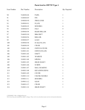
... 5140010-86 5140010-87 Parts List for current parts information. Page 3 All Rights Reserved. Parts list, pricing, and availability subject to change. Please visit www.dewaltservicenet.com for DW735 Type 1 Description Qty Required SWITCH 1 CIRCUIT BREAKER 1 LOCK WASHER 4 NUT 1 SCREW 2 MICRO SWITCH 1 CAP SCREW 2 WASHER 1 WASHER 2 SCREW 4 PLATE 2 WRENCH 1 WRENCH 1 TOP COVER 1 COVER ASSY. 1 COVER PLATE 2 STRAIN RELIEF 1 COVER 2 SPRING 4 RETAINING RING 2 SPROCKET 4 WASHER 2 RETAINING RING 2 ROD 1 PIN 1 HOLDER 1 CARRIAGE 1 COPYRIGHT©...
... 5140010-86 5140010-87 Parts List for current parts information. Page 3 All Rights Reserved. Parts list, pricing, and availability subject to change. Please visit www.dewaltservicenet.com for DW735 Type 1 Description Qty Required SWITCH 1 CIRCUIT BREAKER 1 LOCK WASHER 4 NUT 1 SCREW 2 MICRO SWITCH 1 CAP SCREW 2 WASHER 1 WASHER 2 SCREW 4 PLATE 2 WRENCH 1 WRENCH 1 TOP COVER 1 COVER ASSY. 1 COVER PLATE 2 STRAIN RELIEF 1 COVER 2 SPRING 4 RETAINING RING 2 SPROCKET 4 WASHER 2 RETAINING RING 2 ROD 1 PIN 1 HOLDER 1 CARRIAGE 1 COPYRIGHT©...
Parts Diagram
Page 5
...115 116 Part Number 5140010-...Parts List for current parts information. Page 4 Please visit www.dewaltservicenet.com for DW735 Type 1 Description Qty Required PAWL 1 PIN 1 INDICATOR 1 PLATE 1 BUSHING 4 FELT 4 REAR ROLLER 1 BRACKET 4 ROLLER 1 LEAD 1 SCALE PLATE 1 CHAIN 1 SWITCH COVER 1 SWITCH PLATE 1 SHAFT 1 WASHER 2 SPRING 2 IDLER SHAFT 1 SCREW 4 BALL BEARING 1 RETAINING RING 1 COVER 1 CRANK HANDLE 1 BUSHING 4 GEAR 1 CHAIN 1 IDLER SHAFT 1 COPYRIGHT© 2005. All Rights Reserved. Parts list, pricing, and availability subject to change...
...115 116 Part Number 5140010-...Parts List for current parts information. Page 4 Please visit www.dewaltservicenet.com for DW735 Type 1 Description Qty Required PAWL 1 PIN 1 INDICATOR 1 PLATE 1 BUSHING 4 FELT 4 REAR ROLLER 1 BRACKET 4 ROLLER 1 LEAD 1 SCALE PLATE 1 CHAIN 1 SWITCH COVER 1 SWITCH PLATE 1 SHAFT 1 WASHER 2 SPRING 2 IDLER SHAFT 1 SCREW 4 BALL BEARING 1 RETAINING RING 1 COVER 1 CRANK HANDLE 1 BUSHING 4 GEAR 1 CHAIN 1 IDLER SHAFT 1 COPYRIGHT© 2005. All Rights Reserved. Parts list, pricing, and availability subject to change...

Parts Diagram
Page 7
...-59 5140011-60 5140011-61 5140011-62 000000-00 611732-00 5140010-01 5140010-02 5140010-03 5140014-58 5140011-64 5140011-65 Parts List for current parts information. Please visit www.dewaltservicenet.com for DW735 Type 1 Description Qty Required SPRING 1 SPRING 1 SCALE 1 SCREW 2 SET SCREW 1 ADAPTER 1 DUST CHUTE 1 SCREW 4 PLATE 1 LOCK WASHER 2 SCREW 1 SCREW 4 BUSHING 1 CAP 1 INDICATOR 1 SCALE PLATE 1 SCREW 4 PLATE 1 RETAINING RING 2 No Longer Available 2 NAMEPLATE 1 PAD 1 PAD 1 PAD 1 BASE 1 PIN 1 LOCK WASHER 4 COPYRIGHT© 2005.
...-59 5140011-60 5140011-61 5140011-62 000000-00 611732-00 5140010-01 5140010-02 5140010-03 5140014-58 5140011-64 5140011-65 Parts List for current parts information. Please visit www.dewaltservicenet.com for DW735 Type 1 Description Qty Required SPRING 1 SPRING 1 SCALE 1 SCREW 2 SET SCREW 1 ADAPTER 1 DUST CHUTE 1 SCREW 4 PLATE 1 LOCK WASHER 2 SCREW 1 SCREW 4 BUSHING 1 CAP 1 INDICATOR 1 SCALE PLATE 1 SCREW 4 PLATE 1 RETAINING RING 2 No Longer Available 2 NAMEPLATE 1 PAD 1 PAD 1 PAD 1 BASE 1 PIN 1 LOCK WASHER 4 COPYRIGHT© 2005.

Parts Diagram
Page 8
All Rights Reserved. Parts list, pricing, and availability subject to change. Page 7 Please visit www.dewaltservicenet.com for DW735 Type 1 Description Qty Required WASHER 4 FAN HOUSING 1 RETAINING RING 1 SPRING 1 SPRING CLIP 3 SCREW 4 FAN HOUSING 1 NUT 1 WASHER 1 FAN 1 CAP 1 BALL BEARING 2 SCREW 2 FIELD 1 MOTOR CORD 1 ARMATURE 1 MOTOR HOUSING 1 LOCK WASHER 3 SCREW 4 BRUSH CAP 2 BRUSH 2 BRUSH HOLDER 2 SET SCREW 2 PULLEY 1 STRAIN RELIEF 1 SCREW 1 POST 1 COPYRIGHT© 2005. Item Number 206 207 208 209 210 211 212 213 214 215...
All Rights Reserved. Parts list, pricing, and availability subject to change. Page 7 Please visit www.dewaltservicenet.com for DW735 Type 1 Description Qty Required WASHER 4 FAN HOUSING 1 RETAINING RING 1 SPRING 1 SPRING CLIP 3 SCREW 4 FAN HOUSING 1 NUT 1 WASHER 1 FAN 1 CAP 1 BALL BEARING 2 SCREW 2 FIELD 1 MOTOR CORD 1 ARMATURE 1 MOTOR HOUSING 1 LOCK WASHER 3 SCREW 4 BRUSH CAP 2 BRUSH 2 BRUSH HOLDER 2 SET SCREW 2 PULLEY 1 STRAIN RELIEF 1 SCREW 1 POST 1 COPYRIGHT© 2005. Item Number 206 207 208 209 210 211 212 213 214 215...


