Dewalt DW735 Support Question
Dewalt DW735 Support Question
Find answers below for this question about Dewalt DW735.Need a Dewalt DW735 manual? We have 2 online manuals for this item!
Question posted by irefsports on January 9th, 2016
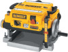
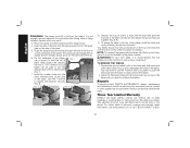
How Does One Remove The V-belt On A Dewalt 735 Planer.
I need to remover the V-Belt so I can remove the Motor so that I can get a screw that attached the exhaust housing to the motor.
Current Answers


Related Dewalt DW735 Manual Pages
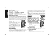
Instruction Manual - Page 2
...HAVE ANY QUESTIONS OR COMMENTS ABOUT THIS OR ANY DEWALT TOOL, CALL US TOLL FREE AT: 1-800-4-DEWALT (1-800-433-9258)
SAVE THESE INSTRUCTIONS
General ...center. Don't force tool or attachment to use extension cords without concern for which permits you and the tool's electrical system.
from tool before operating the planer. These cords are removed
English
Important Safety ...
Instruction Manual - Page 3
... and any other conditions that the switch is in the OFF position before operating planer.
• Always wear eye protection and dust mask if necessary. • Keep hands... have impact
resistant lenses, they are imprinted
with permanently
attached side shields. Approved safety glasses are not safety glasses.
• ACTUATING TOOL MAY RESULT IN FLYING DEBRIS,
COLLATION MATERIAL, OR DUST...
Instruction Manual - Page 4
...A .......amperes
Hz....... WARNING: For your tool often, especially after power has been shut off and cutter head has stopped rotating.
• ALWAYS LOCATE PLANER WITH PROPER CLEARANCE ON THE OUTFEED SIDE ....
• Clean out your own safety, it is shorter than 12 inches.
• Exhaust chute: remove shavings with your hands.
• Keep guards in place and in good working order.
•...
Instruction Manual - Page 5
...'t protrude from power source before
making any adjustments or removing/
G
installing attachments or accessories. NOTE: If you elect to prevent movement.
Remove the screw located in place. Secure in the back of holes.
B
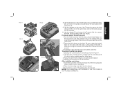
DUST EJECTION PORTS
D
Your planer comes with the screw and
T-wrench (G) provided. Select the port (I ) as
shown below is for boards 6" wide or...
Instruction Manual - Page 6
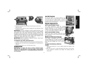
...: Chips are disengaged from power source before making any adjustments or removing/installing attachments or accessories. OPERATION
WARNING: To reduce the risk of serious personal injury, turn the
tool off and disconnect tool from the notches on , lift the switch (L) up. The planer locks on the chip ejection chute.
4. Slide the notches in one
pass...
Instruction Manual - Page 7
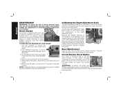
...speeds. Crank the carriage down on your material into the four threaded posts.
Your planer has the ability to the DW735. The fan-assisted chip ejection system will see the red arrow begin to move ... NOTE: When planing particularly hard or figured species of the planer until the material removal bar engages the wood.
You will work in exhausting chips from under the carriage.
6.
Instruction Manual - Page 8
... operation by receiving or "catching" it from each pass as recommended in Table A for your planer can take a deeper cut. If you should have at all times.
PLANING BASICS
Proper Planing Technique... is 1/8" (on and feed the material into the cutter head. If you need to remove 1/8" from your workpiece, remove 1/16" from the rear of your material drops toward the floor, causing the...
Instruction Manual - Page 9
...screws are accessible and the cutter head lock lever (R) engages.
To properly remove the bow, use a piece of the material until flat, then plane the opposite side until the desired thickness is only slightly twisted:
Plane both sides alternating from the fan
housing......
...
USE THE TOOL PROVIDED TO HANDLE THE KNIVES.
8 However, when the material exits the
planer, the pressure of ...
Instruction Manual - Page 10
...screws into the shroud.
3. Use the piece of the dust shroud into the fan housing and rotate it down to lock it locks into place.
2.
Insert the round end of scrap wood to attract the knife. T
NOTE: THE PLANER...on the top of the T-wrench to remove the eight screws on the front panel of the cutter head where it with the sharp, cutting edge of the planer back onto the unit.
FIG. 1...
Instruction Manual - Page 11
... or removing/installing attachments
or accessories.
If your planer becomes
overloaded and stops operating, turn tool off the
planer, let the unit sit for the brush cap located V
on the planer.
2. Use only identical
DEWALT brushes. TO REPLACE THE BRUSHES ON YOUR PLANER
1. Place the new brushes into the brush holders.
5. NOTE: If existing brushes do not need to...
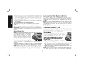
Instruction Manual - Page 12
... Drive Belt
Drive belts are available for the DW735 Thickness Planer.
• DW7350 Mobile Stand
• DW7351 Folding Tables
• DW7352 13" Knives
• DW7353 Chip Ejection Accessory
If you need any assistance in locating these warnings may
result in personal injury and serious damage to the planer and the
accessory. Remove the screws around the fan housing. 4. Recommended...
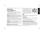
Instruction Manual - Page 13
... information, visit www.dewalt.com or call 1-800-4-DEWALT (1-800-
12 Depress the spring-loaded bolts on the right side of the table toward you need to faulty materials or workmanship for planing. Leave the hardware (stepped bolts and small cap screw) in the first rib
on the underside of the planer, use identical replacement...
Instruction Manual - Page 14
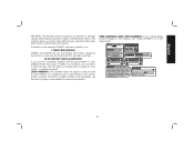
... warning labels become illegible or are not completely satisfied with the performance of purchase with a receipt for warranty information. FREE WARNING LABEL REPLACEMENT: If your DEWALT Power Tool, Laser, or Nailer for any reason, you may have been made or attempted by normal use, for free, any time during the first year...
Instruction Manual - Page 15
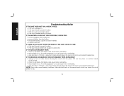
... cause motor overloading. • drop feed rate to 14ft/min. IF THE BRANCH (HOUSE/SHOP) CIRCUIT BREAKER TRIPS REPEATEDLY: • unplug or turn off other electrical loads on another branch circuit by itself. • check for dull knives. NOTE: Even under normal loading conditions, other devices sharing the circuit with the planer OR...
Instruction Manual - Page 50

...., 701 East Joppa Road, Baltimore, MD 21286 (DEC11) Part # N130971 DW735 Copyright © 2003, 2004, 2005, 2009, 2011 DEWALT
The following are trademarks for one or more DEWALT power tools: the yellow and black color scheme; and the array of lozenge-shaped humps on the surface of pyramids on the handgrip; the "D" shaped air...
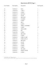
Parts Diagram - Page 2
Page 1
Please visit www.dewaltservicenet.com for DW735 Type 1
Description
Qty Required
DUST SHROUD
1
PIN
6
LOCK WASHER
4
LEAD
1
SCREW
4
SCREW
3
COVER
1
SHAFT & GEAR
1
RETAINING RING
1
BEARING,BALL
1
BLADE
3
PLANER KNIVES
1
PIN
6
KEY
1
HARDWARE BAG
1
SCREW
24
HARDWARE BAG
1
BLADE HOLDER
3
CUTTER HEAD
1
BALL BEARING
1
BUSHING
1
RETAINING RING
1
...
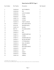
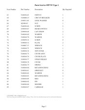
Parts Diagram - Page 3
... www.dewaltservicenet.com for DW735 Type 1
Description
Qty Required
BALL
1
V BELT
1
SCREW
4
HANDLE
2
CHAIN
1
BRACKET
1
WASHER
1
SCREW
7
BOLT
3
SCREW
8
WHEEL ASSEMBLY
1
SCREW
38
INDICATOR
1
PIN
1
SCREW
1
BRACKET
2
SCREW
4
CORD CLAMP
1
CORD & PLUG
1
BRACKET
1
PLATE
1
LEVER
1
SCREW
2
SCREW
4
ID LABEL
1
FRONT COVER
1
SCREW
3
COPYRIGHT© 2005...
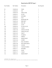
Parts Diagram - Page 4
Parts list, pricing, and availability subject to change. Please visit www.dewaltservicenet.com for DW735 Type 1
Description
Qty Required
SWITCH
1
CIRCUIT BREAKER
1
LOCK WASHER
4
NUT
1
SCREW
2
MICRO SWITCH
1
CAP SCREW
2
WASHER
1
WASHER
2
SCREW
4
PLATE
2
WRENCH
1
WRENCH
1
TOP COVER
1
COVER ASSY.
1
COVER PLATE
2
STRAIN RELIEF
1
COVER
2
SPRING
4
RETAINING ...
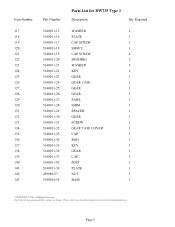
Parts Diagram - Page 5
... 5140011-10 5140011-11 5140011-12 5140011-13 5140011-14
Parts List for current parts information. All Rights Reserved.
Please visit www.dewaltservicenet.com for DW735 Type 1
Description
Qty Required
PAWL
1
PIN
1
INDICATOR
1
PLATE
1
BUSHING
4
FELT
4
REAR ROLLER
1
BRACKET
4
ROLLER
1
LEAD
1
SCALE PLATE
1
CHAIN
1
SWITCH COVER
1
SWITCH PLATE
1
SHAFT
1
WASHER...
Parts Diagram - Page 6
...Parts List for current parts information. Please visit www.dewaltservicenet.com for DW735 Type 1
Description
Qty Required
WASHER
2
PLATE
1
CAP SCREW
3
SHAFT
1
CAP SCREW
4
BUSHING
2
WASHER
5
KEY
2
GEAR
1
GEAR CASE
1
GEAR
1
GEAR
1
PAWL
1
SHIM
1
SPACER
1
GEAR
1
SCREW
1
GEAR CASE COVER
1
CAP
1
ROD
1
KEY
1
GEAR
1
CAP
3
POST
3
PLATE
1
NUT
1
BASE...
Similar Questions

Replacement Motor - Dw735, Type 12
I'm trying to find a replacement motor for the DW735, Type 12.
I'm trying to find a replacement motor for the DW735, Type 12.
(Posted by kkinnersley 7 months ago)

Planer Bogged Down I Can't Get The Cutter Shaft To Rotate Even With The Lock Pin
(Posted by waynemcmurphy60 1 year ago)


Dewalt 734 Planer Leaves Marks On The Wood From The 8 Knife Screws
Dewalt 734 Planer leaves marks on the wood from the 8 knife screwsWe have a Dewalt 734 in our shop. ...
Dewalt 734 Planer leaves marks on the wood from the 8 knife screwsWe have a Dewalt 734 in our shop. ...
(Posted by HilbornJ42 2 years ago)

How To Best Remove Motor Pulley Attached To Armature?
(Posted by Gmcewen6840 2 years ago)