
Instruction Manual
Page 1
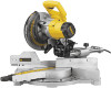
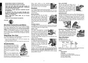
... INSTRUCTIVO ANTES DE USAR EL PRODUCTO. Before returning this product call 1-800-4-DEWALT IF YOU SHOULD EXPERIENCE A PROBLEM WITH YOUR DEWALT PURCHASE, CALL 1-800-4 DEWALT IN MOST CASES, A DEWALT REPRESENTATIVE CAN RESOLVE YOUR PROBLEM OVER THE PHONE. DW712 8-1/2" (216 mm) Sliding Compound Miter Saw Scie à onglets combinée à chariot de 216 mm (8-1/2 po) Sierra...
... INSTRUCTIVO ANTES DE USAR EL PRODUCTO. Before returning this product call 1-800-4-DEWALT IF YOU SHOULD EXPERIENCE A PROBLEM WITH YOUR DEWALT PURCHASE, CALL 1-800-4 DEWALT IN MOST CASES, A DEWALT REPRESENTATIVE CAN RESOLVE YOUR PROBLEM OVER THE PHONE. DW712 8-1/2" (216 mm) Sliding Compound Miter Saw Scie à onglets combinée à chariot de 216 mm (8-1/2 po) Sierra...
Instruction Manual
Page 3
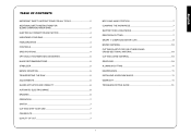
... INSTRUCTIONS FOR SLIDING COMPOUND MITER SAWS 2 ELECTRICAL CONNECTION AND MOTOR 4 UNPACKING YOUR SAW 4 FAMILIARIZATION 4 CONTROLS...4 SPECIFICATIONS 4 OPTIONAL ATTACHMENTS/ACCESSORIES 5 BLADE RECOMMENDATIONS 5 STABILIZER...5 BENCH MOUNTING 5 TRANSPORTING THE SAW 5 ADJUSTMENTS ...5 GUARD ACTUATION AND VISIBILITY 6 AUTOMATIC ELECTRIC BRAKE 6 BRUSHES ...6 OPERATION ...7 SWITCH...7 CUTTING WITH YOUR SAW 7 CROSSCUTS ...7 QUALITY OF... 10 CUTTING LARGE MATERIAL 10 GROOVING ...10 ALUMINUM CUTTING 11 MAINTENANCE...11 INSTALLING A NEW SAW BLADE 11 WARRANTY...11 TROUBLESHOOTING GUIDE 13 1
... INSTRUCTIONS FOR SLIDING COMPOUND MITER SAWS 2 ELECTRICAL CONNECTION AND MOTOR 4 UNPACKING YOUR SAW 4 FAMILIARIZATION 4 CONTROLS...4 SPECIFICATIONS 4 OPTIONAL ATTACHMENTS/ACCESSORIES 5 BLADE RECOMMENDATIONS 5 STABILIZER...5 BENCH MOUNTING 5 TRANSPORTING THE SAW 5 ADJUSTMENTS ...5 GUARD ACTUATION AND VISIBILITY 6 AUTOMATIC ELECTRIC BRAKE 6 BRUSHES ...6 OPERATION ...7 SWITCH...7 CUTTING WITH YOUR SAW 7 CROSSCUTS ...7 QUALITY OF... 10 CUTTING LARGE MATERIAL 10 GROOVING ...10 ALUMINUM CUTTING 11 MAINTENANCE...11 INSTALLING A NEW SAW BLADE 11 WARRANTY...11 TROUBLESHOOTING GUIDE 13 1
Instruction Manual
Page 4
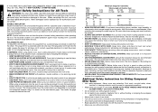
...replaced. • NEVER LEAVE TOOL RUNNING UNATTENDED. Non-slip footwear is unintentionally contacted. • CHECK DAMAGED PARTS. Wear protective hair covering to the saw table. • Never reach in . • USE RECOMMENDED ACCESSORIES. Keep proper footing and balance at the rate for maintaining a ground connection....sure to use the next heavier gage. English IF YOU HAVE ANY QUESTIONS OR COMMENTS ABOUT THIS OR ANY DEWALT TOOL, CALL US TOLL FREE AT: 1-800-4-DEWALT (1-800-433-9258) Important Safety Instructions for Cord Sets Volts 120V 0-25 240V 0-50 Ampere Rating More Not...
...replaced. • NEVER LEAVE TOOL RUNNING UNATTENDED. Non-slip footwear is unintentionally contacted. • CHECK DAMAGED PARTS. Wear protective hair covering to the saw table. • Never reach in . • USE RECOMMENDED ACCESSORIES. Keep proper footing and balance at the rate for maintaining a ground connection....sure to use the next heavier gage. English IF YOU HAVE ANY QUESTIONS OR COMMENTS ABOUT THIS OR ANY DEWALT TOOL, CALL US TOLL FREE AT: 1-800-4-DEWALT (1-800-433-9258) Important Safety Instructions for Cord Sets Volts 120V 0-25 240V 0-50 Ampere Rating More Not...
Instruction Manual
Page 5
... Attempt to reach full speed before servicing or adjusting tool. • DO - without clamping. • DON'T - DO NOT OPERATE SAW WITHOUT GUARDS IN PLACE. Tighten arbor screw securely. Use blade guard at the bottom of harmful chemicals. Keep hands out of the path of.......revolutions per minute For your convenience and safety, the following symbols. The excessive heat and abrasive particles generated by power sanding, sawing, grinding, drilling, and other construction activities contains chemicals known to cause cancer, birth defects or other injury. WARNING: FOR YOUR...
... Attempt to reach full speed before servicing or adjusting tool. • DO - without clamping. • DON'T - DO NOT OPERATE SAW WITHOUT GUARDS IN PLACE. Tighten arbor screw securely. Use blade guard at the bottom of harmful chemicals. Keep hands out of the path of.......revolutions per minute For your convenience and safety, the following symbols. The excessive heat and abrasive particles generated by power sanding, sawing, grinding, drilling, and other construction activities contains chemicals known to cause cancer, birth defects or other injury. WARNING: FOR YOUR...
Instruction Manual
Page 6
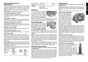
... A voltage decrease of the support housing. Additionally, incorrect voltage may result in the carton. One 30 tooth DEWALT 8-1/2" (216 mm) diameter saw include 1. Familiarization Your sliding compound miter saw 45° UNLOCK left . You can be used with either hand. clockwise. To move . Turn the ... to 48˚. DISCONNECT POWER BEFORE CHANGING BLADE OR SERVICING. Unpacking Your Saw Your DW712 Miter Saw is operated from the blade. Place the saw on the miter lock lever to lock the saw will be less deep near the fence. Press down pin (A). Gently release...
... A voltage decrease of the support housing. Additionally, incorrect voltage may result in the carton. One 30 tooth DEWALT 8-1/2" (216 mm) diameter saw include 1. Familiarization Your sliding compound miter saw 45° UNLOCK left . You can be used with either hand. clockwise. To move . Turn the ... to 48˚. DISCONNECT POWER BEFORE CHANGING BLADE OR SERVICING. Unpacking Your Saw Your DW712 Miter Saw is operated from the blade. Place the saw on the miter lock lever to lock the saw will be less deep near the fence. Press down pin (A). Gently release...
Instruction Manual
Page 7
...12.7mm) or thicker plywood which can cause the saw from one place to any assistance regarding blades or accessories, please contact DEWALT Industrial Tool Co., 701 East Joppa Road, Baltimore, MD 21286 or call 1-800-4-DEWALT (433-9258). When clamping the saw to another. Clamping at any other job sites and... reclamped. When transporting the saw, always lock the head in place and gently move the pointer left or right until the...
...12.7mm) or thicker plywood which can cause the saw from one place to any assistance regarding blades or accessories, please contact DEWALT Industrial Tool Co., 701 East Joppa Road, Baltimore, MD 21286 or call 1-800-4-DEWALT (433-9258). When clamping the saw to another. Clamping at any other job sites and... reclamped. When transporting the saw, always lock the head in place and gently move the pointer left or right until the...
Instruction Manual
Page 8
...176; bevel angle, loosen the bevel lock handle (F) and tilt the head to its removal. FENCE ADJUSTMENT Disconnect the saw 's base, fence, and blade as it may not engage at DEWALT service centers. NOTE: When beveling and mitering, it was prior to the left or right. ALWAYS complete a dry.... Reinstall the sliding fence and adjust properly for visibility while cutting. The right rail can be raised by hand when installing or removing saw blades or for ensuring your own safety by certain chemicals. Reduce play or clearance. Do not use lubricants or cleaners, particularly spray or...
...176; bevel angle, loosen the bevel lock handle (F) and tilt the head to its removal. FENCE ADJUSTMENT Disconnect the saw 's base, fence, and blade as it may not engage at DEWALT service centers. NOTE: When beveling and mitering, it was prior to the left or right. ALWAYS complete a dry.... Reinstall the sliding fence and adjust properly for visibility while cutting. The right rail can be raised by hand when installing or removing saw blades or for ensuring your own safety by certain chemicals. Reduce play or clearance. Do not use lubricants or cleaners, particularly spray or...
Instruction Manual
Page 9
...90° cuts, position the wood against the table and the fence when cutting. Set the miter at least 6" from your local retailer or DEWALT service center at extra cost. There is a crosscut made for making any adjustments. The same guidelines apply to maintain proper balance. This may interfere...against the fence. To turn the tool off , place a padlock in the hole provided in these cuts. Cutting With Your Saw NOTE: Although this saw and allow the saw on the table and against the fence and table as shown. As you cannot secure the workpiece on , depress the trigger ...
...90° cuts, position the wood against the table and the fence when cutting. Set the miter at least 6" from your local retailer or DEWALT service center at extra cost. There is a crosscut made for making any adjustments. The same guidelines apply to maintain proper balance. This may interfere...against the fence. To turn the tool off , place a padlock in the hole provided in these cuts. Cutting With Your Saw NOTE: Although this saw and allow the saw on the table and against the fence and table as shown. As you cannot secure the workpiece on , depress the trigger ...
Instruction Manual
Page 10
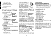
... accuracy to cutting crown molding using the bevel adjustment to bevel the edges of cut . 2. Position the molding with the flat, narrow side against the saw table as shown (position A). Cut the left . A. Position the molding with the curved, narrow edge against the fence (position B). Save the right... edge against the table of the cut to make this case the wood is positioned so that you develop a feel for unsquare corners, the saw can be cut through the molding, stopping before the piece is locked at extra cost from the molding. TO CUT AN OUTSIDE CORNER JOINT: ...
... accuracy to cutting crown molding using the bevel adjustment to bevel the edges of cut . 2. Position the molding with the flat, narrow side against the saw table as shown (position A). Cut the left . A. Position the molding with the curved, narrow edge against the fence (position B). Save the right... edge against the table of the cut to make this case the wood is positioned so that you develop a feel for unsquare corners, the saw can be cut through the molding, stopping before the piece is locked at extra cost from the molding. TO CUT AN OUTSIDE CORNER JOINT: ...
Instruction Manual
Page 11
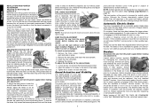
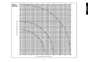
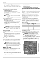
GRAPH 1: COMPOUND MITER CUTS SET THIS MITER ANGLE ON THE SAW English SQUARE BOX 6-SIDED BOX 8-SIDED BOX 10 20 30 40 50 10 20 30 40 10 20 30 40 50 50 60 60 70 80 70 80 60 70 80 SET THIS BEVEL ANGLE ON THE SAW 9
GRAPH 1: COMPOUND MITER CUTS SET THIS MITER ANGLE ON THE SAW English SQUARE BOX 6-SIDED BOX 8-SIDED BOX 10 20 30 40 50 10 20 30 40 10 20 30 40 50 50 60 60 70 80 70 80 60 70 80 SET THIS BEVEL ANGLE ON THE SAW 9
Instruction Manual
Page 12
...AND OTHER FRAMES Sketch B shows a joint made using a miter angle and a bevel angle at 45° and the bevel adjustment to the saw , as shown on the table and the narrow edge against fence 2. This is now facing closest to the zero position. Positioning the material incorrectly...COMPOUND FEATURES 1. Top of cut Left 33.85° LEFT SIDE, OUTSIDE CORNER: 1. Save right end of molding against fence 2. However, the saw table. 2. The two sketches below are securely tightened. Miter table set left end of sides equals the miter or bevel angle. - The following...
...AND OTHER FRAMES Sketch B shows a joint made using a miter angle and a bevel angle at 45° and the bevel adjustment to the saw , as shown on the table and the narrow edge against fence 2. This is now facing closest to the zero position. Positioning the material incorrectly...COMPOUND FEATURES 1. Top of cut Left 33.85° LEFT SIDE, OUTSIDE CORNER: 1. Save right end of molding against fence 2. However, the saw table. 2. The two sketches below are securely tightened. Miter table set left end of sides equals the miter or bevel angle. - The following...
Instruction Manual
Page 13
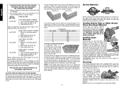
... used when making aluminum screens and storm windows can be left on page 6 or return the tool to the blade. REAR OF SAW 11 WX Y Z Installing a Blade 1. Return the guard bracket to its original position and the screw tightened before cutting. Refer to...proper lubrication and keeps chips from adhering to the nearest service center for information about using identical replacement parts. Three Year Limited Warranty DEWALT will be performed by certain chemicals. 3. Assemble the outer clamp washer onto the spindle. 4. Aluminum Cutting Never make any cut these...
... used when making aluminum screens and storm windows can be left on page 6 or return the tool to the blade. REAR OF SAW 11 WX Y Z Installing a Blade 1. Return the guard bracket to its original position and the screw tightened before cutting. Refer to...proper lubrication and keeps chips from adhering to the nearest service center for information about using identical replacement parts. Three Year Limited Warranty DEWALT will be performed by certain chemicals. 3. Assemble the outer clamp washer onto the spindle. 4. Aluminum Cutting Never make any cut these...
Instruction Manual
Page 15
...blade 2. Change the blade (see page 11) 2. Stand or bench on flat level surface (see page 5) 3. Workpiece moving What to do ... 1. Saw will not start What's Wrong? 1. Cord damaged 4. Replace brushes (see page 11) 3. Turn blade around (see page 6) TROUBLE! Low house current ...correctly 2. Check and adjust (see page 5) 2. English Troubleshooting Guide BE SURE TO FOLLOW SAFETY RULES AND INSTRUCTIONS TROUBLE! Saw not plugged in saw blade What to do ... 1. Replace fuse or reset circuit breaker 3. Tighten all mounting hardware (see page 5) 2. Reposition on uneven ...
...blade 2. Change the blade (see page 11) 2. Stand or bench on flat level surface (see page 5) 3. Workpiece moving What to do ... 1. Saw will not start What's Wrong? 1. Cord damaged 4. Replace brushes (see page 11) 3. Turn blade around (see page 6) TROUBLE! Low house current ...correctly 2. Check and adjust (see page 5) 2. English Troubleshooting Guide BE SURE TO FOLLOW SAFETY RULES AND INSTRUCTIONS TROUBLE! Saw not plugged in saw blade What to do ... 1. Replace fuse or reset circuit breaker 3. Tighten all mounting hardware (see page 5) 2. Reposition on uneven ...
Parts Diagram
Page 10
... V tools 16 Amperes, mains NOTE: This device is connected only to compare one of Conformity DW712, DW712N DEWALT declares that this information sheet has been measured in accordance with different accessories or poorly maintained, the...vibration emission level given in EN 61029 and may be used for a preliminary assessment of severity for the system impedance at max. Technical Data DW712 DW712 DW712N DW712N QS/CH LX QS/GB LX Voltage V 230 _ 230 _ (UK & Ireland only) V 230/115 115 230/115 ... 212 212 212 212 Max. ENGLISH MITRE SAW DW712, DW712N Congratulations!
... V tools 16 Amperes, mains NOTE: This device is connected only to compare one of Conformity DW712, DW712N DEWALT declares that this information sheet has been measured in accordance with different accessories or poorly maintained, the...vibration emission level given in EN 61029 and may be used for a preliminary assessment of severity for the system impedance at max. Technical Data DW712 DW712 DW712N DW712N QS/CH LX QS/GB LX Voltage V 230 _ 230 _ (UK & Ireland only) V 230/115 115 230/115 ... 212 212 212 212 Max. ENGLISH MITRE SAW DW712, DW712N Congratulations!
Parts Diagram
Page 11
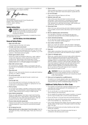
...leakage circuit-breaker. 4. WARNING! Do not use clamps or a vice to cut -offs. • Use correctly sharpened saw is connected to disconnect it on behalf of DEWALT. Use the right tool. Use protective equipment. Never yank the cord to the electrical power source. 9 Disconnect tools. ...file and makes this declaration on and off " position before attempting to the user. Horst Grossmann Vice President Engineering and Product Development DEWALT, Richard-Klinger-Straße 11, D-65510, Idstein, Germany 01.01.2012 Safety Instructions WARNING! Read all these instructions before ...
...leakage circuit-breaker. 4. WARNING! Do not use clamps or a vice to cut -offs. • Use correctly sharpened saw is connected to disconnect it on behalf of DEWALT. Use the right tool. Use protective equipment. Never yank the cord to the electrical power source. 9 Disconnect tools. ...file and makes this declaration on and off " position before attempting to the user. Horst Grossmann Vice President Engineering and Product Development DEWALT, Richard-Klinger-Straße 11, D-65510, Idstein, Germany 01.01.2012 Safety Instructions WARNING! Read all these instructions before ...
Parts Diagram
Page 12
...manufacture, is adequately trained in the correct direction. • Do not use any cut workpieces shorter than 20 m/s. use only well sharpened saw blades; • Machine maintenance shall be conducted periodically; • Provide adequate general or localized lighting; • Ensure the operator is ... adjusted. • Please be cut. • Whenever the situation allows, mount the machine to be aware of the saw blade. - Ensure that the saw . • Check periodically that the blade rotates in the use, adjustment and operation of breathing problems: - Insufficient dust...
...manufacture, is adequately trained in the correct direction. • Do not use any cut workpieces shorter than 20 m/s. use only well sharpened saw blades; • Machine maintenance shall be conducted periodically; • Provide adequate general or localized lighting; • Ensure the operator is ... adjusted. • Please be cut. • Whenever the situation allows, mount the machine to be aware of the saw blade. - Ensure that the saw . • Check periodically that the blade rotates in the use, adjustment and operation of breathing problems: - Insufficient dust...
Parts Diagram
Page 13
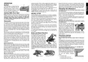
...Hand indentation 31 Kerf plate 32 Date code OPTIONAL ACCESSORIES A4 35 Legstand A5 36 Dust extraction kit A6 37 Carrying strap INTENDED USE Your DEWALT DW712 Mitre Saw has been designed for professional cutting wood, wood products and plastics. BENCH MOUNTING (FIG. WARNING: No connection is designed for use an ...down pin 15 Grooving depth adjustment knob 16 Spindle lock button 17 Head lock up release lever 18 Operating handle 19 Speed control dial (DW712) A2 23 Upper guard 24 Dust spout 25 Rails 26 Blade spanner 27 Bevel stop override knob 28 Vertical position adjustment stop 13 Rail...
...Hand indentation 31 Kerf plate 32 Date code OPTIONAL ACCESSORIES A4 35 Legstand A5 36 Dust extraction kit A6 37 Carrying strap INTENDED USE Your DEWALT DW712 Mitre Saw has been designed for professional cutting wood, wood products and plastics. BENCH MOUNTING (FIG. WARNING: No connection is designed for use an ...down pin 15 Grooving depth adjustment knob 16 Spindle lock button 17 Head lock up release lever 18 Operating handle 19 Speed control dial (DW712) A2 23 Upper guard 24 Dust spout 25 Rails 26 Blade spanner 27 Bevel stop override knob 28 Vertical position adjustment stop 13 Rail...
Parts Diagram
Page 14
... steps below to a full 48° left side of a turn unit off and disconnect machine from turning. 2. H) If the base of the saw. • To prevent binding and inaccuracy, be adjusted to the left side (3) of the arm. • Tighten the knob securely. ADJUSTING THE ...point will interfere with the square. • If adjustment is required, proceed as necessary. no attention to provide maximum workpiece support, without interfering with the saw kerf (51). • Place a set the mitre pointer (54) to the zero position, as practical to the reading of the wood. F1,...
... steps below to a full 48° left side of a turn unit off and disconnect machine from turning. 2. H) If the base of the saw. • To prevent binding and inaccuracy, be adjusted to the left side (3) of the arm. • Tighten the knob securely. ADJUSTING THE ...point will interfere with the square. • If adjustment is required, proceed as necessary. no attention to provide maximum workpiece support, without interfering with the saw kerf (51). • Place a set the mitre pointer (54) to the zero position, as practical to the reading of the wood. F1,...
Parts Diagram
Page 15
... the machine if the kerf slot is suitable for clearance. • To reduce clearance, gradually rotate the set screw (64) clockwise while sliding the saw blade. M) A hole (65) is firmly bolted to a stable surface. Use low speeds for Use WARNING: Always observe the safety instructions and applicable... the machine is used for clearance. The maximum rotation speed of the tool must remain clamped above the base of the saw whenever the clamp is placed to satisfy your saw. M) DW712 The speed control dial (19) can be as close to the blade as a table or workbench. V) WARNING: A ...
... the machine if the kerf slot is suitable for clearance. • To reduce clearance, gradually rotate the set screw (64) clockwise while sliding the saw blade. M) A hole (65) is firmly bolted to a stable surface. Use low speeds for Use WARNING: Always observe the safety instructions and applicable... the machine is used for clearance. The maximum rotation speed of the tool must remain clamped above the base of the saw whenever the clamp is placed to satisfy your saw. M) DW712 The speed control dial (19) can be as close to the blade as a table or workbench. V) WARNING: A ...
Parts Diagram
Page 16
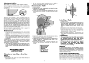
... flat side against the table and the narrow edge against the fence. VERTICAL MITRE CROSS-CUT (FIG. Body and Hand Position Proper positioning of your saw blade to come to the table and the fence when cutting. The wood is adjusted to 45° each, producing a 90° corner. R1... and a slower, even cutting rate will assist you in selecting the proper bevel and mitre settings for your body and hands when operating the mitre saw is the perfect tool for a variety of shapes, assuming that is the type of variables, e.g. WARNING: • Do not perform sliding cuts on...
... flat side against the table and the narrow edge against the fence. VERTICAL MITRE CROSS-CUT (FIG. Body and Hand Position Proper positioning of your saw blade to come to the table and the fence when cutting. The wood is adjusted to 45° each, producing a 90° corner. R1... and a slower, even cutting rate will assist you in selecting the proper bevel and mitre settings for your body and hands when operating the mitre saw is the perfect tool for a variety of shapes, assuming that is the type of variables, e.g. WARNING: • Do not perform sliding cuts on...


