Owners Manual
Page 2
... the manufacturer. 09. This product should be placed in a built-in wire to an antenna discharge unit, size of grounding conductors, location of your DENON DEALER. 3. Power Sources - This plug will fit into the product, c) If the product has been exposed to rain or water, d) If the... plug attachment and not by the manufacturer, or sold with Part 15 of overhead power lines or other hazards. Do not place anything inside Do not place metal objects or spill liquid inside the system. D-107, USW-107 and USC-107 Serial No. CAUTION RISK OF ELECTRIC SHOCK DO NOT OPEN ...
... the manufacturer. 09. This product should be placed in a built-in wire to an antenna discharge unit, size of grounding conductors, location of your DENON DEALER. 3. Power Sources - This plug will fit into the product, c) If the product has been exposed to rain or water, d) If the... plug attachment and not by the manufacturer, or sold with Part 15 of overhead power lines or other hazards. Do not place anything inside Do not place metal objects or spill liquid inside the system. D-107, USW-107 and USC-107 Serial No. CAUTION RISK OF ELECTRIC SHOCK DO NOT OPEN ...
Owners Manual
Page 5
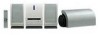
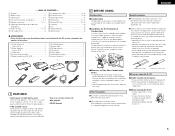
... this unit or other audio/video equipment, etc. 2 When using the D-107 2 Under normal circumstances • Always remove the disc and turn off .... the carton: q Stand (Main unit 1 Screw (4×10 2 w Stand (Speaker 2 Screw (4×10 4 e Cable cover 1 r System conector cable 1 t Remote control unit (RC-909 1 q w y R03/AAA batteries 2 u Speaker cable 2 i AM loop antenna 1 ... station list 1 e r 2 BEFORE USING Condensation 2 Condensation Condensation can occur on the operating parts within the unit and normal operation will form on the audio and video of the unit. This...
... this unit or other audio/video equipment, etc. 2 When using the D-107 2 Under normal circumstances • Always remove the disc and turn off .... the carton: q Stand (Main unit 1 Screw (4×10 2 w Stand (Speaker 2 Screw (4×10 4 e Cable cover 1 r System conector cable 1 t Remote control unit (RC-909 1 q w y R03/AAA batteries 2 u Speaker cable 2 i AM loop antenna 1 ... station list 1 e r 2 BEFORE USING Condensation 2 Condensation Condensation can occur on the operating parts within the unit and normal operation will form on the audio and video of the unit. This...
Owners Manual
Page 7
... Core wire (copper-colored) Core wire (silver-colored) • Gently pull the cord to check that it with the wider part of the system cable's R L connector facing upwards. w Insert the speaker cord. Press Insert the plug securely, pressing it in all the ..., then mount with the driver part of the system cable's connector facing upwards. SPEAKER SYSTEM IMPEDANCE:6 16 Push down and insert the speaker cord. SPEAKER SYSTEM IMPEDANCE:6 16 SPEAKER SYSTEM IMPEDANCE:6 16 R L R L 7 q Lower the lever. SYSTEM CONNECTOR SPEAKER SYSTEM IMPEDANCE:6 16 Connect with the ...
... Core wire (copper-colored) Core wire (silver-colored) • Gently pull the cord to check that it with the wider part of the system cable's R L connector facing upwards. w Insert the speaker cord. Press Insert the plug securely, pressing it in all the ..., then mount with the driver part of the system cable's connector facing upwards. SPEAKER SYSTEM IMPEDANCE:6 16 Push down and insert the speaker cord. SPEAKER SYSTEM IMPEDANCE:6 16 SPEAKER SYSTEM IMPEDANCE:6 16 R L R L 7 q Lower the lever. SYSTEM CONNECTOR SPEAKER SYSTEM IMPEDANCE:6 16 Connect with the ...
Owners Manual
Page 8
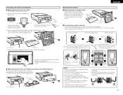
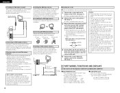
...8 lever. Ground AM outdoor antenna Approx. 12 meters 4 PART NAMES, FUNCTIONS AND DISPLAYS 8 meters or greater (1) CD receiver (D-107), Speakers (USC-107) and Subwoofer (USW-107) q ON/STANDBY button • Press to button on ...to the antenna terminal (ANTENNA AM). Also be mounted on a wall. 1 Connect the system cable to the bottom of the D-107. (See page 7.) There is no need to mount the stand. 2 Connect the cords...107 and the speakers onto the screws in this to the point of cable entry as it may have not reach it easily, making it difficult to operate. • Note that Denon...
...8 lever. Ground AM outdoor antenna Approx. 12 meters 4 PART NAMES, FUNCTIONS AND DISPLAYS 8 meters or greater (1) CD receiver (D-107), Speakers (USC-107) and Subwoofer (USW-107) q ON/STANDBY button • Press to button on ...to the antenna terminal (ANTENNA AM). Also be mounted on a wall. 1 Connect the system cable to the bottom of the D-107. (See page 7.) There is no need to mount the stand. 2 Connect the cords...107 and the speakers onto the screws in this to the point of cable entry as it may have not reach it easily, making it difficult to operate. • Note that Denon...

