
Owners Manual
Page 1
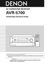
IN VIDEO SELECT TONE DEFEAT PANEL DIMMER MODE SOURCE INPUT REC / MULTI PRECISION AUDIO COMPONENT / AV SURROUND RECEIVER AVR-5700 START SYSTEM CALL SET CALL DVD 1 TV/DBS 4 VCR-1 7 VCR-2 +10 VDP 2 V.AUX 5 CD 8 0 RC-853 LEARNED/TX POWER OFF ON /...5CH DSP STEREO SURROUND SCREEN STEREO SIMULATION SELECT DOWN UP BASS TREBLE INPUT MODE ANALOG 6CH EXT. AV SURROUND RECEIVER AVR-5700 OPERATING INSTRUCTIONS REMOTE SENSOR INPUT SELECTOR ON / STANDBY ON / STANDBY HOME THX CINEMA TAPE-2 MON OFF CH INDICATOR L C R LOCK SL S SR LFE VOLUME LEVEL SURROUND SPEAKER A...
IN VIDEO SELECT TONE DEFEAT PANEL DIMMER MODE SOURCE INPUT REC / MULTI PRECISION AUDIO COMPONENT / AV SURROUND RECEIVER AVR-5700 START SYSTEM CALL SET CALL DVD 1 TV/DBS 4 VCR-1 7 VCR-2 +10 VDP 2 V.AUX 5 CD 8 0 RC-853 LEARNED/TX POWER OFF ON /...5CH DSP STEREO SURROUND SCREEN STEREO SIMULATION SELECT DOWN UP BASS TREBLE INPUT MODE ANALOG 6CH EXT. AV SURROUND RECEIVER AVR-5700 OPERATING INSTRUCTIONS REMOTE SENSOR INPUT SELECTOR ON / STANDBY ON / STANDBY HOME THX CINEMA TAPE-2 MON OFF CH INDICATOR L C R LOCK SL S SR LFE VOLUME LEVEL SURROUND SPEAKER A...
Owners Manual
Page 4
..., always unplug the power cord and disconnect the connection cords between the top, back and sides of this unit and the wall or other audio components when moving the set for North America model only 1 Y R6P/AA batteries........2 U AM loop antenna......1 E Service station list...........1 I... Before turning the power switch on Check once again that all connections are proper and that you for choosing the DENON AVR-5700 Digital Surround A / V receiver. This remarkable component has been engineered to occur particularly when using outdoor antennas and 75 Ω/ohms coaxial cables. ...
..., always unplug the power cord and disconnect the connection cords between the top, back and sides of this unit and the wall or other audio components when moving the set for North America model only 1 Y R6P/AA batteries........2 U AM loop antenna......1 E Service station list...........1 I... Before turning the power switch on Check once again that all connections are proper and that you for choosing the DENON AVR-5700 Digital Surround A / V receiver. This remarkable component has been engineered to occur particularly when using outdoor antennas and 75 Ω/ohms coaxial cables. ...
Owners Manual
Page 5
.... 4. Component Video Switching In addition to composite video and "S" video switching, the AVR5700 provides 2 sets of component video (Y, R-Y, B-Y)... door This unit has a door on AC line voltage. The DENON AVR-5700 provides the ability to open it. 4 FEATURES 1. 3 CAUTIONS ...THX Ultra certified for top performance with the widest range of speaker systems. Rated at 140 watts into 8 Ω/ohms, the amp channels feature additional low impedance drive capability. 10.Future Sound Format Upgrade Capability via Eight Channel Inputs & Outputs For future multi-channel audio format(s), the AVR-5700...
.... 4. Component Video Switching In addition to composite video and "S" video switching, the AVR5700 provides 2 sets of component video (Y, R-Y, B-Y)... door This unit has a door on AC line voltage. The DENON AVR-5700 provides the ability to open it. 4 FEATURES 1. 3 CAUTIONS ...THX Ultra certified for top performance with the widest range of speaker systems. Rated at 140 watts into 8 Ω/ohms, the amp channels feature additional low impedance drive capability. 10.Future Sound Format Upgrade Capability via Eight Channel Inputs & Outputs For future multi-channel audio format(s), the AVR-5700...
Owners Manual
Page 7
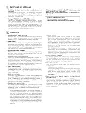
... L MD/ TAPRE-1 L TAPE-2 AUDIO MONITOR OUT-1 MONITOR OUT-2 DVD IN VDP TV / DBS V.AUX VCR-1 VCR-2 OUT VCR-1 DOLBY DIGITAL IN RF 1 VCR-2 VIDEO S-VIDEO OPTICAL 2 3 OPTICAL-5 4 IN OUT DIGITAL Note on the AVR-5700 is also possible to connect a video disc player, DVD player, video camcorder, game machine, etc., to the...SR SL MD/ R TAPE-1 ER EL TAPE-2 8CH EXT. Note, however, that the AVR-5700's onscreen display signals are input to the AUDIO TV/DBS IN jacks using a 75 Ω/ohms video coaxial pin plug cord. • The monitor TV can be connected in sound quality. •...
... L MD/ TAPRE-1 L TAPE-2 AUDIO MONITOR OUT-1 MONITOR OUT-2 DVD IN VDP TV / DBS V.AUX VCR-1 VCR-2 OUT VCR-1 DOLBY DIGITAL IN RF 1 VCR-2 VIDEO S-VIDEO OPTICAL 2 3 OPTICAL-5 4 IN OUT DIGITAL Note on the AVR-5700 is also possible to connect a video disc player, DVD player, video camcorder, game machine, etc., to the...SR SL MD/ R TAPE-1 ER EL TAPE-2 8CH EXT. Note, however, that the AVR-5700's onscreen display signals are input to the AUDIO TV/DBS IN jacks using a 75 Ω/ohms video coaxial pin plug cord. • The monitor TV can be connected in sound quality. •...
Owners Manual
Page 8
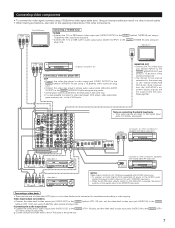
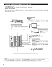
...video disc player's S-Video output jack to the S-VIDEO MONITOR OUT-2 jack. Note, however, that the AVR-5700's on -screen display signals are not output from the color difference (component) video signal MONITOR OUT jacks. 8 TV or satellite broadcast tuner S-VIDEO OUT IN Video deck 1 Connecting the video decks • Connect the video... PREOUT R OUT R VCR-1 VCR-2 MD / TAPE-1 TAPE-2 AUDIO MONITOR OUT-1 MONITOR OUT-2 DVD IN VDP TV / DBS L V.AUX L VCR-1 VCR-2 OUT VCR-1 VCR-2 VIDEO S-VIDEO S-VIDEO IN Monitor TV S-VIDEO OUT Connecting a TV/DBS tuner • Connect the TV's or...
...video disc player's S-Video output jack to the S-VIDEO MONITOR OUT-2 jack. Note, however, that the AVR-5700's on -screen display signals are not output from the color difference (component) video signal MONITOR OUT jacks. 8 TV or satellite broadcast tuner S-VIDEO OUT IN Video deck 1 Connecting the video decks • Connect the video... PREOUT R OUT R VCR-1 VCR-2 MD / TAPE-1 TAPE-2 AUDIO MONITOR OUT-1 MONITOR OUT-2 DVD IN VDP TV / DBS L V.AUX L VCR-1 VCR-2 OUT VCR-1 VCR-2 VIDEO S-VIDEO S-VIDEO IN Monitor TV S-VIDEO OUT Connecting a TV/DBS tuner • Connect the TV's or...
Owners Manual
Page 10
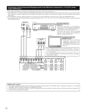
...refer to the operating instructions of displaying HDTV signals. In addition, the video signals input to the VIDEO input (yellow) and S-Video input jacks are not output to the color difference (component) video jacks. • The AVR-5700's on some TVs, monitors or video components ("Pr, Pb and Y", "R-Y, B-Y and Y", "Cr, Cb...COMPONENT DVD IN jack using 75 Ω/ohms coaxial video pinplug cords. • The color difference input jacks may damage the AVR-5700 and connected components. 10 Y IN CB CR Y CB CR DVD IN TV/DBS COMPONENT VIDEO Y CB CR MONITOR OUT ROOM TO ROOM REMOTE...
...refer to the operating instructions of displaying HDTV signals. In addition, the video signals input to the VIDEO input (yellow) and S-Video input jacks are not output to the color difference (component) video jacks. • The AVR-5700's on some TVs, monitors or video components ("Pr, Pb and Y", "R-Y, B-Y and Y", "Cr, Cb...COMPONENT DVD IN jack using 75 Ω/ohms coaxial video pinplug cords. • The color difference input jacks may damage the AVR-5700 and connected components. 10 Y IN CB CR Y CB CR DVD IN TV/DBS COMPONENT VIDEO Y CB CR MONITOR OUT ROOM TO ROOM REMOTE...
Owners Manual
Page 15
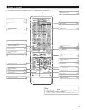
AUDIO DECK MD CD LOCK MUTING AVR/AVC VIDEO TUNING DVD TV VDP VCR SYSTEM SETUP SURROUND PARAMETER ...button 32) PANEL button 39) Multi source button 40) NOTE • The shaded buttons do not function with the AVR-5700. (Nothing happens when they are pressed.) The button indicated 2, however, can be used with the learning function. ... ( ). LEDs (indicators 33) SYSTEM CALL buttons 34) Input source selector buttons 37) System buttons 29) HOME THX CINEMA button 47) Surround buttons 49) INPUT MODE selector buttons 37) Mode selector switches 29) Tuner system buttons 29...
AUDIO DECK MD CD LOCK MUTING AVR/AVC VIDEO TUNING DVD TV VDP VCR SYSTEM SETUP SURROUND PARAMETER ...button 32) PANEL button 39) Multi source button 40) NOTE • The shaded buttons do not function with the AVR-5700. (Nothing happens when they are pressed.) The button indicated 2, however, can be used with the learning function. ... ( ). LEDs (indicators 33) SYSTEM CALL buttons 34) Input source selector buttons 37) System buttons 29) HOME THX CINEMA button 47) Surround buttons 49) INPUT MODE selector buttons 37) Mode selector switches 29) Tuner system buttons 29...
Owners Manual
Page 16
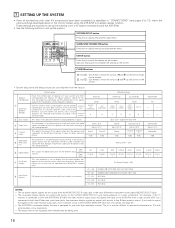
... distorted sounds from a video source (VDP, etc.) connected to both the AVR-5700's S-Video and video monitor output jacks and signals are input to the AVR-5700 from being used for ...PARAMETER button Press this function when using the AVR-5700's on-screen display function. Also use with which the audio signals are received automatically and stored in the memory. B1 ...on the screen. Front L & R 3.6 m (12 ft) Front L Front R 0 dB 0 dB Bass Out = Subwoofer Only THX Center Surround L & R 3.6 m (12 ft) Center 0 dB 3.0 m (10 ft) Surround L Surround R 0 dB 0...
... distorted sounds from a video source (VDP, etc.) connected to both the AVR-5700's S-Video and video monitor output jacks and signals are input to the AVR-5700 from being used for ...PARAMETER button Press this function when using the AVR-5700's on-screen display function. Also use with which the audio signals are received automatically and stored in the memory. B1 ...on the screen. Front L & R 3.6 m (12 ft) Front L Front R 0 dB 0 dB Bass Out = Subwoofer Only THX Center Surround L & R 3.6 m (12 ft) Center 0 dB 3.0 m (10 ft) Surround L Surround R 0 dB 0...
Owners Manual
Page 17
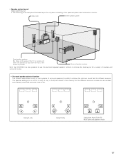
Surround speaker systems With the AVR-5700 it is set. The speaker settings (on or off for A only, B only or A+B) are stored in the memory for the different surround modes and are ...
Surround speaker systems With the AVR-5700 it is set. The speaker settings (on or off for A only, B only or A+B) are stored in the memory for the different surround modes and are ...
Owners Manual
Page 22
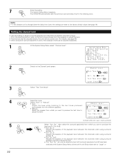
... is set to the Channel Level screen. Sp.: A Adjusts the balance of the playback level between the channels when using surround speaker A. • Surr. The AVR-5700 automatically sets the optimum surround delay time for the listening room. Sp.: B Adjusts the balance of the playback level between the different channels is selected...
... is set to the Channel Level screen. Sp.: A Adjusts the balance of the playback level between the channels when using surround speaker A. • Surr. The AVR-5700 automatically sets the optimum surround delay time for the listening room. Sp.: B Adjusts the balance of the playback level between the different channels is selected...
Owners Manual
Page 24
... Start", then select "Yes". Increase the master volume level until the test noise is at the point where the test noise starts sounding distorted. The AVR-5700 automatically sets the subwoofer peak limit level. ENTER This prevents future inadvertent subwoofer overload due to excessively strong bass content when the master volume control...
... Start", then select "Yes". Increase the master volume level until the test noise is at the point where the test noise starts sounding distorted. The AVR-5700 automatically sets the subwoofer peak limit level. ENTER This prevents future inadvertent subwoofer overload due to excessively strong bass content when the master volume control...
Owners Manual
Page 25
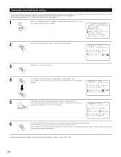
...", set the peak limit to any jack other digital recorder. In this case, the input resistance of the AVR-5700 for digital recording between a digital audio source (stereo - 2 channel) and a digital audio recorder. • Do not connect the output of the component connected to the OPTICAL 5 OUT jack on the...limits and are used. 2 If "Yes" is insufficient. The System Setup Menu reappears. ENTER NOTES: • The OPTICAL 5 jacks on the AVR-5700's rear panel are equipped with low input resistance, check that the sound is not clipped at sections where the signal is strong on a DAT ...
...", set the peak limit to any jack other digital recorder. In this case, the input resistance of the AVR-5700 for digital recording between a digital audio source (stereo - 2 channel) and a digital audio recorder. • Do not connect the output of the component connected to the OPTICAL 5 OUT jack on the...limits and are used. 2 If "Yes" is insufficient. The System Setup Menu reappears. ENTER NOTES: • The OPTICAL 5 jacks on the AVR-5700's rear panel are equipped with low input resistance, check that the sound is not clipped at sections where the signal is strong on a DAT ...
Owners Manual
Page 27
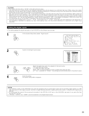
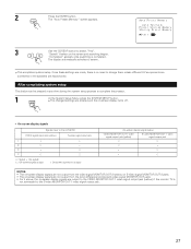
...SYSTEM SETUP button. 2 The changed settings are entered and the on-screen display turns off. • On-screen display signals Signals input to the AVR-5700 VIDEO signal input jack (yellow) S-video signal input jack 1 E E 2 A E 3 E A 4 A A (A: Signal E : No signal) (A: On-screen signals output E: On...output to change them unless different AV components are connected or the speakers are made, there is no need to the VIDEO MONITOR OUT-1 video signal output jack (yellow) if the monitor TV is completed. The "Auto Preset Memory" screen appears. Once these...
...SYSTEM SETUP button. 2 The changed settings are entered and the on-screen display turns off. • On-screen display signals Signals input to the AVR-5700 VIDEO signal input jack (yellow) S-video signal input jack 1 E E 2 A E 3 E A 4 A A (A: Signal E : No signal) (A: On-screen signals output E: On...output to change them unless different AV components are connected or the speakers are made, there is no need to the VIDEO MONITOR OUT-1 video signal output jack (yellow) if the monitor TV is completed. The "Auto Preset Memory" screen appears. Once these...
Owners Manual
Page 28
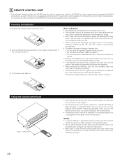
...-circuit, disassemble, heat or dispose of batteries in flames. • Remove the batteries from the main unit, but other remote control compatible DENON components as possible. NOTES: • It may be cleared if no batteries are in permanent memory, however. Notes on the main unit and...or leakage of up to 30 degrees with respect to operate non-DENON remote control compatible video components. 8 REMOTE CONTROL UNIT • The included remote control unit (RC-853) can be used to operate not only the AVR-5700 but this depends on the frequency of approximately 7 meters/22 ...
...-circuit, disassemble, heat or dispose of batteries in flames. • Remove the batteries from the main unit, but other remote control compatible DENON components as possible. NOTES: • It may be cleared if no batteries are in permanent memory, however. Notes on the main unit and...or leakage of up to 30 degrees with respect to operate non-DENON remote control compatible video components. 8 REMOTE CONTROL UNIT • The included remote control unit (RC-853) can be used to operate not only the AVR-5700 but this depends on the frequency of approximately 7 meters/22 ...
Owners Manual
Page 29
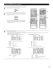
...MD / TAPE-1 9 CHANNEL TAPE-2 MON TV/VCR A / B VOLUME DISC SKIP+ DOLBY / DTS HOME THX CINEMA SURROUND DIRECT DSP SIMULATION 5CH STEREO INPUT MODE ANALOG STEREO EXT.IN MASTER VOL. up /down VOLUME DISC ... AVR-5700 (sections A and B) will function. CD player (CD) and MD recorder (MD) system buttons 2. AUDIO DECK MD CD LOCK MUTING AVR/AVC VIDEO TUNING...6 MD / TAPE-1 9 CHANNEL SHIFT : Switch preset channel range CHANNEL : Preset channel +, - Operating DENON audio components • Turn on the power of the different components before operating them. 1 Set mode switch 1 ...
...MD / TAPE-1 9 CHANNEL TAPE-2 MON TV/VCR A / B VOLUME DISC SKIP+ DOLBY / DTS HOME THX CINEMA SURROUND DIRECT DSP SIMULATION 5CH STEREO INPUT MODE ANALOG STEREO EXT.IN MASTER VOL. up /down VOLUME DISC ... AVR-5700 (sections A and B) will function. CD player (CD) and MD recorder (MD) system buttons 2. AUDIO DECK MD CD LOCK MUTING AVR/AVC VIDEO TUNING...6 MD / TAPE-1 9 CHANNEL SHIFT : Switch preset channel range CHANNEL : Preset channel +, - Operating DENON audio components • Turn on the power of the different components before operating them. 1 Set mode switch 1 ...
Owners Manual
Page 33
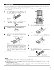
AUDIO 2 1,8 VOLUME DISC SKIP+ DOLBY / DTS HOME THX... and the learning mode is already full, and the code you can "teach" the AVR-5700's remote control to "learn" the codes from the component's original remote control. •...work properly. Both the START and LEARNED/TX indicators flash. AUDIO DECK MD CD LOCK MUTING AVR/AVC VIDEO TUNING DVD TV VDP VCR SYSTEM SETUP SURROUND PARAMETER BAND ... the memory is cancelled. Learning function • If your AV component is not a DENON product or it cannot be operated with the preset memory codesets, you have just attempted ...
AUDIO 2 1,8 VOLUME DISC SKIP+ DOLBY / DTS HOME THX... and the learning mode is already full, and the code you can "teach" the AVR-5700's remote control to "learn" the codes from the component's original remote control. •...work properly. Both the START and LEARNED/TX indicators flash. AUDIO DECK MD CD LOCK MUTING AVR/AVC VIDEO TUNING DVD TV VDP VCR SYSTEM SETUP SURROUND PARAMETER BAND ... the memory is cancelled. Learning function • If your AV component is not a DENON product or it cannot be operated with the preset memory codesets, you have just attempted ...
Owners Manual
Page 37
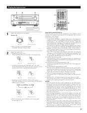
...TAPE-1 9 CHANNEL TAPE-2 MON TV/VCR A / B 3 2 VOLUME DISC SKIP+ DOLBY / DTS HOME THX CINEMA SURROUND DIRECT DSP SIMULATION 5CH STEREO INPUT MODE ANALOG STEREO EXT.IN MASTER VOL. IN (on the remote control... Lightly press on the disc. IN) mode Press the 6CH/8CH EXT. AUDIO DECK MD CD LOCK MUTING AVR/AVC VIDEO TUNING DVD TV VDP VCR SYSTEM SETUP SURROUND PARAMETER TITLE MENU/GUIDE 5 Input ... to the digital input jacks are identified and decoding and playback are played in the AVR-5700's surround decoder is detected at the Dolby Digital AC-3 RF jack, the RF signals...
...TAPE-1 9 CHANNEL TAPE-2 MON TV/VCR A / B 3 2 VOLUME DISC SKIP+ DOLBY / DTS HOME THX CINEMA SURROUND DIRECT DSP SIMULATION 5CH STEREO INPUT MODE ANALOG STEREO EXT.IN MASTER VOL. IN (on the remote control... Lightly press on the disc. IN) mode Press the 6CH/8CH EXT. AUDIO DECK MD CD LOCK MUTING AVR/AVC VIDEO TUNING DVD TV VDP VCR SYSTEM SETUP SURROUND PARAMETER TITLE MENU/GUIDE 5 Input ... to the digital input jacks are identified and decoding and playback are played in the AVR-5700's surround decoder is detected at the Dolby Digital AC-3 RF jack, the RF signals...
Owners Manual
Page 40
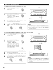
...which you want to record appears on the set's display. • The indicator for the selected program source lights. • When the AVR-5700 is in the MULTI mode are also output from the DAT/TAPE-1 and VCR recording output terminals. • Digital signals are not output ...; Recording sources other than digital inputs selected in the REC OUT mode are also output to the multi source audio/video output jacks. • Digital signals are not output from the REC SOURCE or audio/video output jacks. [2] Outputting a program source to an amplifier, etc., in a different room (MULTI mode) ...
...which you want to record appears on the set's display. • The indicator for the selected program source lights. • When the AVR-5700 is in the MULTI mode are also output from the DAT/TAPE-1 and VCR recording output terminals. • Digital signals are not output ...; Recording sources other than digital inputs selected in the REC OUT mode are also output to the multi source audio/video output jacks. • Digital signals are not output from the REC SOURCE or audio/video output jacks. [2] Outputting a program source to an amplifier, etc., in a different room (MULTI mode) ...
Owners Manual
Page 42
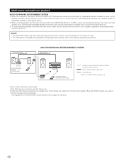
...programmable remote control unit. ANOTHER ROOM MULTI ROOM MUSIC ENTERTAINMENT SYSTEM MAIN ROOM INTEGRATED AMPLIFIER PROGRAMMABLE REMOTE CONTROL UNIT RC-617 RC-616 AVR-5700 SYSTEM REMOTE CONTROL UNIT RC-853 ROOM-TO-ROOM REMOTE CONTROL SYSTEM (separately sold devices, refer to the devices' operating instructions. ...; When the outputs of separately sold ) control line MULTI SOURCE AUDIO signal cable SPEAKER cable 2 Refer to CONNECTIONS on the diagram below.) • When a sold separately room-to-room remote control unit (DENON RC-616, 617 or 618) is wired and connected between the...
...programmable remote control unit. ANOTHER ROOM MULTI ROOM MUSIC ENTERTAINMENT SYSTEM MAIN ROOM INTEGRATED AMPLIFIER PROGRAMMABLE REMOTE CONTROL UNIT RC-617 RC-616 AVR-5700 SYSTEM REMOTE CONTROL UNIT RC-853 ROOM-TO-ROOM REMOTE CONTROL SYSTEM (separately sold devices, refer to the devices' operating instructions. ...; When the outputs of separately sold ) control line MULTI SOURCE AUDIO signal cable SPEAKER cable 2 Refer to CONNECTIONS on the diagram below.) • When a sold separately room-to-room remote control unit (DENON RC-616, 617 or 618) is wired and connected between the...
Owners Manual
Page 44
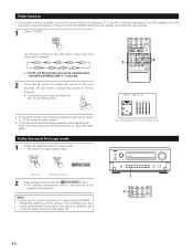
...mode 1 Select the Dolby Surround Pro Logic mode. • The Dolby Pro Logic indicator lights. This is selected. 1 DOLBY / DTS HOME THX CINEMA SURROUND DIRECT DSP SIMULATION 5CH STEREO INPUT MODE ANALOG STEREO EXT.IN MASTER VOL. Fader function • This function makes it for example to...during the system setup process (page 18). The AVR-5700 sets the mode automatically according to the manuals of the front channels (FL, C and FR) or the rear channels (SL and SR) together. AUDIO DECK MD CD LOCK MUTING AVR/AVC VIDEO TUNING DVD TV VDP VCR SYSTEM SETUP SURROUND ...
...mode 1 Select the Dolby Surround Pro Logic mode. • The Dolby Pro Logic indicator lights. This is selected. 1 DOLBY / DTS HOME THX CINEMA SURROUND DIRECT DSP SIMULATION 5CH STEREO INPUT MODE ANALOG STEREO EXT.IN MASTER VOL. Fader function • This function makes it for example to...during the system setup process (page 18). The AVR-5700 sets the mode automatically according to the manuals of the front channels (FL, C and FR) or the rear channels (SL and SR) together. AUDIO DECK MD CD LOCK MUTING AVR/AVC VIDEO TUNING DVD TV VDP VCR SYSTEM SETUP SURROUND ...


