
Owners Manual
Page 1
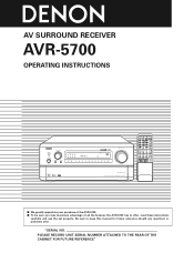
...arise. Be sure to offer, read these instructions carefully and use the set properly. IN VIDEO SELECT TONE DEFEAT PANEL DIMMER MODE SOURCE INPUT REC / MULTI PRECISION AUDIO COMPONENT / AV SURROUND RECEIVER AVR-5700 START SYSTEM CALL SET CALL DVD 1 TV/DBS 4 VCR-1 7 VCR-2 +10 VDP ...DSP SIMULATION 5CH STEREO INPUT MODE ANALOG STEREO EXT.IN MASTER VOL. "SERIAL NO. AV SURROUND RECEIVER AVR-5700 OPERATING INSTRUCTIONS REMOTE SENSOR INPUT SELECTOR ON / STANDBY ON / STANDBY HOME THX CINEMA TAPE-2 MON OFF CH INDICATOR L C R LOCK SL S SR LFE VOLUME LEVEL ...
...arise. Be sure to offer, read these instructions carefully and use the set properly. IN VIDEO SELECT TONE DEFEAT PANEL DIMMER MODE SOURCE INPUT REC / MULTI PRECISION AUDIO COMPONENT / AV SURROUND RECEIVER AVR-5700 START SYSTEM CALL SET CALL DVD 1 TV/DBS 4 VCR-1 7 VCR-2 +10 VDP ...DSP SIMULATION 5CH STEREO INPUT MODE ANALOG STEREO EXT.IN MASTER VOL. "SERIAL NO. AV SURROUND RECEIVER AVR-5700 OPERATING INSTRUCTIONS REMOTE SENSOR INPUT SELECTOR ON / STANDBY ON / STANDBY HOME THX CINEMA TAPE-2 MON OFF CH INDICATOR L C R LOCK SL S SR LFE VOLUME LEVEL ...
Owners Manual
Page 4
... INSTALLATION Noise or disturbance of this unit and the wall or other components. • Store this unit or any other audio components when moving the set for choosing the DENON AVR-5700 Digital Surround A / V receiver. This remarkable component has been engineered to occur particularly when using microprocessors is provided with the warranty in a safe place...
... INSTALLATION Noise or disturbance of this unit and the wall or other components. • Store this unit or any other audio components when moving the set for choosing the DENON AVR-5700 Digital Surround A / V receiver. This remarkable component has been engineered to occur particularly when using microprocessors is provided with the warranty in a safe place...
Owners Manual
Page 5
... AVR-5700 is provided with 7.1 channel (seven main channels, plus one source (visual) while listening to another source (audio). • Five Identical Power Amplifiers Featuring discrete high current power transistors, the power amp section is THX Ultra certified for optimum high fidelity reproduction of music and movie soundtracks. 6. 24 Bit AL Processing A feature of DENON...
... AVR-5700 is provided with 7.1 channel (seven main channels, plus one source (visual) while listening to another source (audio). • Five Identical Power Amplifiers Featuring discrete high current power transistors, the power amp section is THX Ultra certified for optimum high fidelity reproduction of music and movie soundtracks. 6. 24 Bit AL Processing A feature of DENON...
Owners Manual
Page 7
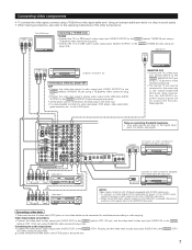
... on the AVR-5700 is also possible to connect a video disc player, DVD player, video camcorder, game machine, etc., to the VIDEO MONITOR OUT-2 jack. For details, see page 6. Connecting the audio output jacks • Connect the video deck's audio output jacks (AUDIO OUT) to the AUDIO VCR-1 IN jacks, and the video deck's audio input jacks (AUDIO IN) to the AUDIO VCR-1 OUT...
... on the AVR-5700 is also possible to connect a video disc player, DVD player, video camcorder, game machine, etc., to the VIDEO MONITOR OUT-2 jack. For details, see page 6. Connecting the audio output jacks • Connect the video deck's audio output jacks (AUDIO OUT) to the AUDIO VCR-1 IN jacks, and the video deck's audio input jacks (AUDIO IN) to the AUDIO VCR-1 OUT...
Owners Manual
Page 8
...AUDIO MONITOR OUT-1 MONITOR OUT-2 DVD IN VDP TV / DBS L V.AUX L VCR-1 VCR-2 OUT VCR-1 VCR-2 VIDEO S-VIDEO S-VIDEO IN Monitor TV S-VIDEO OUT Connecting a TV/DBS tuner • Connect the TV's or DBS tuner's S video output jack (SVIDEO OUTPUT) to the equipment's instruction manuals. Note, however, that the AVR-5700...'s on -screen display signals are not output from the pin jack outputs. DVD VDP ANTENNA TERMINALS TV/ DBS 6CH EXT. When connecting this unit with equipment that video signals input from the S-jacks are only output...
...AUDIO MONITOR OUT-1 MONITOR OUT-2 DVD IN VDP TV / DBS L V.AUX L VCR-1 VCR-2 OUT VCR-1 VCR-2 VIDEO S-VIDEO S-VIDEO IN Monitor TV S-VIDEO OUT Connecting a TV/DBS tuner • Connect the TV's or DBS tuner's S video output jack (SVIDEO OUTPUT) to the equipment's instruction manuals. Note, however, that the AVR-5700...'s on -screen display signals are not output from the pin jack outputs. DVD VDP ANTENNA TERMINALS TV/ DBS 6CH EXT. When connecting this unit with equipment that video signals input from the S-jacks are only output...
Owners Manual
Page 10
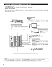
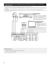
... may cut off the sound and may be connected to the color difference (component) video jacks. • The AVR-5700's on some TVs, monitors or video components ("Pr, Pb and Y", "R-Y, B-Y and Y", "Cr, Cb and Y", etc.). Connecting a Video Component Equipped with component video outputs are labeled Y, Pb, Pr, or Y, Cb, Cr, or Y, R-Y, B-Y. Connecting a monitor TV MONITOR OUT...
... may cut off the sound and may be connected to the color difference (component) video jacks. • The AVR-5700's on some TVs, monitors or video components ("Pr, Pb and Y", "R-Y, B-Y and Y", "Cr, Cb and Y", etc.). Connecting a Video Component Equipped with component video outputs are labeled Y, Pb, Pr, or Y, Cb, Cr, or Y, R-Y, B-Y. Connecting a monitor TV MONITOR OUT...
Owners Manual
Page 15
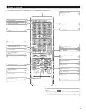
...of these parts, refer to the pages given in parentheses ( ). AUDIO DECK MD CD LOCK MUTING AVR/AVC VIDEO TUNING DVD TV VDP VCR SYSTEM SETUP SURROUND PARAMETER BAND MODE MEMORY ...button 39) Multi source button 40) NOTE • The shaded buttons do not function with the AVR-5700. (Nothing happens when they are pressed.) The button indicated 2, however, can be used with ...(indicators 33) SYSTEM CALL buttons 34) Input source selector buttons 37) System buttons 29) HOME THX CINEMA button 47) Surround buttons 49) INPUT MODE selector buttons 37) Mode selector switches 29) ...
...of these parts, refer to the pages given in parentheses ( ). AUDIO DECK MD CD LOCK MUTING AVR/AVC VIDEO TUNING DVD TV VDP VCR SYSTEM SETUP SURROUND PARAMETER BAND MODE MEMORY ...button 39) Multi source button 40) NOTE • The shaded buttons do not function with the AVR-5700. (Nothing happens when they are pressed.) The button indicated 2, however, can be used with ...(indicators 33) SYSTEM CALL buttons 34) Input source selector buttons 37) System buttons 29) HOME THX CINEMA button 47) Surround buttons 49) INPUT MODE selector buttons 37) Mode selector switches 29) ...
Owners Manual
Page 16
...subwoofer from damage and prevent unpleasant distorted sounds from the speakers and subwoofer for use this to the S-Video monitor output. Front L & R 3.6 m (12 ft) Front L Front R 0 dB 0 dB Bass Out = Subwoofer Only THX Center Surround L & R 3.6 m (12 ft) Center 0 dB 3.0 m (10 ft) ...received automatically and stored in order to obtain optimum effects. Sub Woofer 3.6 m (12 ft) Subwoofer 0 dB V. For example, if the TV monitor is for optimizing the timing with which the audio signals are produced from a video source (VDP, etc.) connected to both the AVR-5700's S-Video and video...
...subwoofer from damage and prevent unpleasant distorted sounds from the speakers and subwoofer for use this to the S-Video monitor output. Front L & R 3.6 m (12 ft) Front L Front R 0 dB 0 dB Bass Out = Subwoofer Only THX Center Surround L & R 3.6 m (12 ft) Center 0 dB 3.0 m (10 ft) ...received automatically and stored in order to obtain optimum effects. Sub Woofer 3.6 m (12 ft) Subwoofer 0 dB V. For example, if the TV monitor is for optimizing the timing with which the audio signals are produced from a video source (VDP, etc.) connected to both the AVR-5700's S-Video and video...
Owners Manual
Page 17
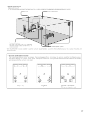
... both of two systems of surround speakers (A and B) to choose the best layout for a variety of the screen as possible. Surround speaker systems With the AVR-5700 it is also possible to use the surround speaker selector function to achieve the optimum sound field for different sources. • Speaker system layout Basic...
... both of two systems of surround speakers (A and B) to choose the best layout for a variety of the screen as possible. Surround speaker systems With the AVR-5700 it is also possible to use the surround speaker selector function to achieve the optimum sound field for different sources. • Speaker system layout Basic...
Owners Manual
Page 22
... speakers to adjust the level. • The level can only be adjusted directly from which you want to "Large" or 7 ENTER Enter the setting. The AVR-5700 automatically sets the optimum surround delay time for the listening room. can also be selected when both A and B have been selected at the same time...
... speakers to adjust the level. • The level can only be adjusted directly from which you want to "Large" or 7 ENTER Enter the setting. The AVR-5700 automatically sets the optimum surround delay time for the listening room. can also be selected when both A and B have been selected at the same time...
Owners Manual
Page 24
... button at a high level. 2 Clear the subwoofer's peak limit level setting by controlling the maximum bass volume level. from the speaker system. 5 MASTER VOL. The AVR-5700 automatically sets the subwoofer peak limit level. The screen switches and a test noise is distorted. The test noise (bass sound) is distorted when it sounds...
... button at a high level. 2 Clear the subwoofer's peak limit level setting by controlling the maximum bass volume level. from the speaker system. 5 MASTER VOL. The AVR-5700 automatically sets the subwoofer peak limit level. The screen switches and a test noise is distorted. The test noise (bass sound) is distorted when it sounds...
Owners Manual
Page 25
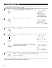
...master volume set the peak limit to the default values. 4 Enter the setting. ENTER NOTES: • The OPTICAL 5 jacks on the AVR-5700's rear panel are equipped with low input resistance, check that the sound is not clipped at sections where the signal is strong on a DAT... other digital recorder. Setting the digital inputs • This setting assigns the digital input jacks of the AVR-5700 for digital recording between a digital audio source (stereo - 2 channel) and a digital audio recorder. • Do not connect the output of the subwoofer or front speakers is selected for which...
...master volume set the peak limit to the default values. 4 Enter the setting. ENTER NOTES: • The OPTICAL 5 jacks on the AVR-5700's rear panel are equipped with low input resistance, check that the sound is not clipped at sections where the signal is strong on a DAT... other digital recorder. Setting the digital inputs • This setting assigns the digital input jacks of the AVR-5700 for digital recording between a digital audio source (stereo - 2 channel) and a digital audio recorder. • Do not connect the output of the subwoofer or front speakers is selected for which...
Owners Manual
Page 27
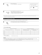
.... "Completed" appears once searching is no need to the AVR-5700 VIDEO signal input jack (yellow) S-video signal input jack 1 E E 2 A E 3 E A 4 A A (A: Signal E : No signal) (A: On-screen signals output E: On-screen signals not output) On-screen display signal output VIDEO MONITOR OUT-1 video signal output jack (yellow) S-video MONITOR OUT-1 video signal output jack A A A E E A E A NOTES: • The on-screen display...
.... "Completed" appears once searching is no need to the AVR-5700 VIDEO signal input jack (yellow) S-video signal input jack 1 E E 2 A E 3 E A 4 A A (A: Signal E : No signal) (A: On-screen signals output E: On-screen signals not output) On-screen display signal output VIDEO MONITOR OUT-1 video signal output jack (yellow) S-video MONITOR OUT-1 video signal output jack A A A E E A E A NOTES: • The on-screen display...
Owners Manual
Page 28
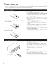
...seconds. Furthermore, it for learning the control signals of remote control units of up to 30 degrees with respect to operate non-DENON remote control compatible video components. Doing so may result in malfunction. • Neon signs or other devices emitting pulse-type noise nearby may be ...be replaced with new ones if the set does not operate even when the remote control unit is exposed to operate not only the AVR-5700 but this depends on the main unit and remote control unit simultaneously. The factory-installed codes are obstacles in permanent memory, however. ...
...seconds. Furthermore, it for learning the control signals of remote control units of up to 30 degrees with respect to operate non-DENON remote control compatible video components. Doing so may result in malfunction. • Neon signs or other devices emitting pulse-type noise nearby may be ...be replaced with new ones if the set does not operate even when the remote control unit is exposed to operate not only the AVR-5700 but this depends on the main unit and remote control unit simultaneously. The factory-installed codes are obstacles in permanent memory, however. ...
Owners Manual
Page 29
...DENON audio components • Turn on the power of components may not be operated with a wide range of infrared controlled components, some models of the different components before operating them. 1 Set mode switch 1 to "AUDIO (AVR... CHANNEL TAPE-2 MON TV/VCR A / B A VOLUME DISC SKIP+ DOLBY / DTS HOME THX CINEMA SURROUND DIRECT DSP SIMULATION 5CH STEREO INPUT MODE ANALOG STEREO EXT.IN MASTER VOL. Use this...the component to the position for the basic functions of the AVR-5700 (sections A and B) will function. AUDIO AVR/AVC VIDEO 2 Set mode switch 2 to be operated. (The ...
...DENON audio components • Turn on the power of components may not be operated with a wide range of infrared controlled components, some models of the different components before operating them. 1 Set mode switch 1 to "AUDIO (AVR... CHANNEL TAPE-2 MON TV/VCR A / B A VOLUME DISC SKIP+ DOLBY / DTS HOME THX CINEMA SURROUND DIRECT DSP SIMULATION 5CH STEREO INPUT MODE ANALOG STEREO EXT.IN MASTER VOL. Use this...the component to the position for the basic functions of the AVR-5700 (sections A and B) will function. AUDIO AVR/AVC VIDEO 2 Set mode switch 2 to be operated. (The ...
Owners Manual
Page 33
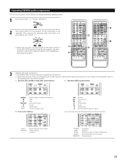
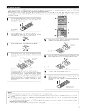
... If a non-learnable button is already full, and the code you can "teach" the AVR-5700's remote control to the VIDEO side for the VCR, VDP and TV. This unit's remote control unit Approx. 5 cm...pen etc., to be "learned". Both the START and LEARNED/TX indicators flash. AUDIO 2 1,8 VOLUME DISC SKIP+ DOLBY / DTS HOME THX CINEMA SURROUND DIRECT DSP SIMULATION 5CH STEREO INPUT MODE ANALOG STEREO EXT.IN MASTER VOL.... is pressed or two or more buttons are the buttons which can be operated with the DENON system codes for the CD player, DAT and tape deck, the buttons which can also ...
... If a non-learnable button is already full, and the code you can "teach" the AVR-5700's remote control to the VIDEO side for the VCR, VDP and TV. This unit's remote control unit Approx. 5 cm...pen etc., to be "learned". Both the START and LEARNED/TX indicators flash. AUDIO 2 1,8 VOLUME DISC SKIP+ DOLBY / DTS HOME THX CINEMA SURROUND DIRECT DSP SIMULATION 5CH STEREO INPUT MODE ANALOG STEREO EXT.IN MASTER VOL.... is pressed or two or more buttons are the buttons which can be operated with the DENON system codes for the CD player, DAT and tape deck, the buttons which can also ...
Owners Manual
Page 37
.../ TAPE-1 9 CHANNEL TAPE-2 MON TV/VCR A / B 3 2 VOLUME DISC SKIP+ DOLBY / DTS HOME THX CINEMA SURROUND DIRECT DSP SIMULATION 5CH STEREO INPUT MODE ANALOG STEREO EXT.IN MASTER VOL. If this mode, the types ...not be selected for the selected input source are detected and the program in the AVR-5700's surround decoder is interrupted. • When playing PCM signals in the DIGITAL (... skip, the AC-3 RF signal is selected automatically upon playback. AUDIO DECK MD CD LOCK MUTING AVR/AVC VIDEO TUNING DVD TV VDP VCR SYSTEM SETUP SURROUND PARAMETER TITLE MENU/GUIDE...
.../ TAPE-1 9 CHANNEL TAPE-2 MON TV/VCR A / B 3 2 VOLUME DISC SKIP+ DOLBY / DTS HOME THX CINEMA SURROUND DIRECT DSP SIMULATION 5CH STEREO INPUT MODE ANALOG STEREO EXT.IN MASTER VOL. If this mode, the types ...not be selected for the selected input source are detected and the program in the AVR-5700's surround decoder is interrupted. • When playing PCM signals in the DIGITAL (... skip, the AC-3 RF signal is selected automatically upon playback. AUDIO DECK MD CD LOCK MUTING AVR/AVC VIDEO TUNING DVD TV VDP VCR SYSTEM SETUP SURROUND PARAMETER TITLE MENU/GUIDE...
Owners Manual
Page 40
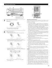
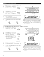
...; Recording sources other than digital inputs selected in the REC OUT mode are also output to the multi source audio/video output jacks. • Digital signals are not output from the REC SOURCE or audio/video output jacks. [2] Outputting a program source to an amplifier, etc., in a different room (MULTI mode)...source you want to output appears on the set 's display. • The indicator for the selected program source lights. • When the AVR-5700 is in the MULTI mode are also output from the DAT/TAPE-1 and VCR recording output terminals. • Digital signals are not output ...
...; Recording sources other than digital inputs selected in the REC OUT mode are also output to the multi source audio/video output jacks. • Digital signals are not output from the REC SOURCE or audio/video output jacks. [2] Outputting a program source to an amplifier, etc., in a different room (MULTI mode)...source you want to output appears on the set 's display. • The indicator for the selected program source lights. • When the AVR-5700 is in the MULTI mode are also output from the DAT/TAPE-1 and VCR recording output terminals. • Digital signals are not output ...
Owners Manual
Page 42
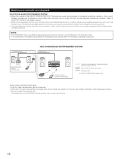
...UNIT RC-617 RC-616 AVR-5700 SYSTEM REMOTE CONTROL UNIT RC-853 ROOM-TO-ROOM REMOTE CONTROL SYSTEM (separately sold) control line MULTI SOURCE AUDIO signal cable SPEAKER cable 2 Refer to CONNECTIONS on the diagram below.) • When a sold separately room-to-room remote control unit (DENON RC-616, 617 or ...618) is connected, the signals input to the IN jack are output from the OUT jack directly. (Example: RC616 signals are output.) • Do not connect only the OUT jack. (The signals from the AVR-5700's remote sensor are installed. (...
...UNIT RC-617 RC-616 AVR-5700 SYSTEM REMOTE CONTROL UNIT RC-853 ROOM-TO-ROOM REMOTE CONTROL SYSTEM (separately sold) control line MULTI SOURCE AUDIO signal cable SPEAKER cable 2 Refer to CONNECTIONS on the diagram below.) • When a sold separately room-to-room remote control unit (DENON RC-616, 617 or ...618) is connected, the signals input to the IN jack are output from the OUT jack directly. (Example: RC616 signals are output.) • Do not connect only the OUT jack. (The signals from the AVR-5700's remote sensor are installed. (...
Owners Manual
Page 44
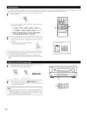
... positions when playing multi-channel music sources. 1 Select "FADER". AUDIO DECK MD CD LOCK MUTING AVR/AVC VIDEO TUNING DVD TV VDP VCR SYSTEM SETUP SURROUND PARAMETER BAND MODE MEMORY...is adjusted lowest can only be faded to the manuals of the respective components. The AVR-5700 sets the mode automatically according to reduce the volume of speakers set during the system...only displayed when setting the fader control. 1 1 VOLUME DISC SKIP+ DOLBY / DTS HOME THX CINEMA SURROUND DIRECT DSP SIMULATION 5CH STEREO INPUT MODE ANALOG STEREO EXT.IN MASTER VOL. 44 ...
... positions when playing multi-channel music sources. 1 Select "FADER". AUDIO DECK MD CD LOCK MUTING AVR/AVC VIDEO TUNING DVD TV VDP VCR SYSTEM SETUP SURROUND PARAMETER BAND MODE MEMORY...is adjusted lowest can only be faded to the manuals of the respective components. The AVR-5700 sets the mode automatically according to reduce the volume of speakers set during the system...only displayed when setting the fader control. 1 1 VOLUME DISC SKIP+ DOLBY / DTS HOME THX CINEMA SURROUND DIRECT DSP SIMULATION 5CH STEREO INPUT MODE ANALOG STEREO EXT.IN MASTER VOL. 44 ...


