
Literature/Product Sheet
Page 1
... Surround 4. Rock Arena 6. A/V Surround Receiver AVR-587 7.1 A/V Surround Receiver features XM-HD Surround and iPod command and control capability. Jazz Club 5. Matrix s High-quality surround sound reproduction • High resolution 32bit floating point DSP • 96 kHz processing circuit s Denon's basic design for high-quality sound reproduction • Power transformer for high power driven • Twin drive...
... Surround 4. Rock Arena 6. A/V Surround Receiver AVR-587 7.1 A/V Surround Receiver features XM-HD Surround and iPod command and control capability. Jazz Club 5. Matrix s High-quality surround sound reproduction • High resolution 32bit floating point DSP • 96 kHz processing circuit s Denon's basic design for high-quality sound reproduction • Power transformer for high power driven • Twin drive...

Literature/Product Sheet
Page 2
... 87.5 - 107.9 MHz Usable sensitivity 1.0 µV (11.2 dBf) AM Section Tuning frequency range 520 - 1710 kHz Usable sensitivity 18 µV General Power supply AC 120 V, 60 Hz Power consumption 4.3 A Dimensions 17-3/32" (W) x 5-25/32" (H) x 16-9/64"(D) 434 (W) x 147 (H) x 417 (D) mm Weight 11.2 kg,...DVD/VDP, TV/DBS, VCR, V.AUX(FRONT) Video Outputs 1 set of delay effects and unnatural artifacts, from all of Denon's high-grade A/V receiver, the AVR-587 lets you adjust parameters so that you do not need to select the mode again for that program. s Variable subwoofer crossover...
... 87.5 - 107.9 MHz Usable sensitivity 1.0 µV (11.2 dBf) AM Section Tuning frequency range 520 - 1710 kHz Usable sensitivity 18 µV General Power supply AC 120 V, 60 Hz Power consumption 4.3 A Dimensions 17-3/32" (W) x 5-25/32" (H) x 16-9/64"(D) 434 (W) x 147 (H) x 417 (D) mm Weight 11.2 kg,...DVD/VDP, TV/DBS, VCR, V.AUX(FRONT) Video Outputs 1 set of delay effects and unnatural artifacts, from all of Denon's high-grade A/V receiver, the AVR-587 lets you adjust parameters so that you do not need to select the mode again for that program. s Variable subwoofer crossover...

Owners Manual - English
Page 2
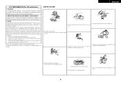
... convenience receptacles as radiators, heat registers, stoves, or other products (including amplifiers) that may be adhered to lightning and power-line surges. 17. Servicing - SAFETY INSTRUCTIONS 1. All operating and use instructions should not be read before cleaning. and the.... 21. Lightning - Wall or Ceiling Mounting - The product should be of sufficient magnitude to constitute a risk of overhead power lines or other controls may cause hazards. 7. NO USER-SERVICEABLE PARTS INSIDE. Retain Instructions - for the grounding electrode. or...
... convenience receptacles as radiators, heat registers, stoves, or other products (including amplifiers) that may be adhered to lightning and power-line surges. 17. Servicing - SAFETY INSTRUCTIONS 1. All operating and use instructions should not be read before cleaning. and the.... 21. Lightning - Wall or Ceiling Mounting - The product should be of sufficient magnitude to constitute a risk of overhead power lines or other controls may cause hazards. 7. NO USER-SERVICEABLE PARTS INSIDE. Retain Instructions - for the grounding electrode. or...
Owners Manual - English
Page 3
...If this product does cause harmful interference to radio or television reception, which the receiver is subject to distribute this type of the FCC Rules. Allow for long ...provide reasonable protection against harmful interference in a residential installation. Modification not expressly approved by DENON may not cause harmful interference, and (2) this manual, meets FCC requirements. However, .... 3. This Class B digital apparatus complies with the apparatus. • Unplug the power cord when not using the apparatus for sufficient heat dispersion when installed in contact with ...
...If this product does cause harmful interference to radio or television reception, which the receiver is subject to distribute this type of the FCC Rules. Allow for long ...provide reasonable protection against harmful interference in a residential installation. Modification not expressly approved by DENON may not cause harmful interference, and (2) this manual, meets FCC requirements. However, .... 3. This Class B digital apparatus complies with the apparatus. • Unplug the power cord when not using the apparatus for sufficient heat dispersion when installed in contact with ...
Owners Manual - English
Page 4
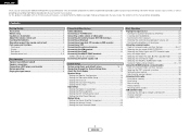
...XM terminal 13 Connecting the iPod 14 Connecting the MULTI ZONE terminals ZONE2 speaker out connections 14 Connecting the power supply cord 15 System Setup System setup items and default values 16, 17 Navigating through the System Setup items... 22 Setting the EXT. IN Subwoofer Level 22 Setting the Auto Preset Memory 22 Option Setup Setting the Power Amplifier Assignment 23 Setting the Volume Control 23 Setting the Auto Surround Mode 24 Basic Operation Playing the input... this manual before you begin hookup and operation that you for choosing the DENON AVR-587 AV Surround Receiver.
...XM terminal 13 Connecting the iPod 14 Connecting the MULTI ZONE terminals ZONE2 speaker out connections 14 Connecting the power supply cord 15 System Setup System setup items and default values 16, 17 Navigating through the System Setup items... 22 Setting the EXT. IN Subwoofer Level 22 Setting the Auto Preset Memory 22 Option Setup Setting the Power Amplifier Assignment 23 Setting the Volume Control 23 Setting the Auto Surround Mode 24 Basic Operation Playing the input... this manual before you begin hookup and operation that you for choosing the DENON AVR-587 AV Surround Receiver.
Owners Manual - English
Page 5
... in noise. Troubleshooting 51 Specifications 52 List of preset codes End of the microprocessor (Reset 43 Operating the remote control unit Operating DENON audio components 44 Setting the preset memory function 44 Operating a component stored in the preset memory ····45 ~...away from the actual unit for explanation purposes. To prevent short-circuits or damaged wires in the connection cables, always unplug the power supply cord and disconnect the connection cables between all connections are correct and that all other audio components when moving the unit. ...
... in noise. Troubleshooting 51 Specifications 52 List of preset codes End of the microprocessor (Reset 43 Operating the remote control unit Operating DENON audio components 44 Setting the preset memory function 44 Operating a component stored in the preset memory ····45 ~...away from the actual unit for explanation purposes. To prevent short-circuits or damaged wires in the connection cables, always unplug the power supply cord and disconnect the connection cables between all connections are correct and that all other audio components when moving the unit. ...

Owners Manual - English
Page 7
...) !3 SURR. MODE/SURR. u TUNED indicator This lights when an FM/AM broadcast has been received. 4 ENGLISH IN button 25) @7 Remote control sensor 3) @8 INPUT MODE button 25) @9 INPUT SELECTOR knob 25) Display uy t r t !2 q w e r y u i o !0 !1 !3 !4 !5 q w e q Power operation button (ON/STANDBY 9) w Power indicator 9) e Power switch 9, 43) r Headphones jack (PHONES 26) t ANALOG button 25) y SPEAKER buttons 9, 43) u ZONE2 button...
...) !3 SURR. MODE/SURR. u TUNED indicator This lights when an FM/AM broadcast has been received. 4 ENGLISH IN button 25) @7 Remote control sensor 3) @8 INPUT MODE button 25) @9 INPUT SELECTOR knob 25) Display uy t r t !2 q w e r y u i o !0 !1 !3 !4 !5 q w e q Power operation button (ON/STANDBY 9) w Power indicator 9) e Power switch 9, 43) r Headphones jack (PHONES 26) t ANALOG button 25) y SPEAKER buttons 9, 43) u ZONE2 button...

Owners Manual - English
Page 8
...q PRE OUT terminal 7) w EXT. IN terminals 11) e DIGITAL terminals (Optical/Coaxial 8, 12) r AUDIO OUT terminals 8, 12) t Speaker terminals 7, 14) y Power supply cord 15) u AC outlets 15) i COMPONENT VIDEO terminals 8) o VIDEO/S-VIDEO terminals 8) !0 DOCK CONTROL jack 14) !1 AUDIO IN terminals 8) !2 XM terminal... (D, H, F, G 18) DISPLAY button 45) DIMMER/MENU button 26, 45) [ Front ] Getting Started Remote control signal transmitter 3) Power buttons 9, 45) Tuner system/System buttons 37, 38) Master volume control buttons 9, 25) MUTING button 26) NIGHT/AUDIO button 39, ...
...q PRE OUT terminal 7) w EXT. IN terminals 11) e DIGITAL terminals (Optical/Coaxial 8, 12) r AUDIO OUT terminals 8, 12) t Speaker terminals 7, 14) y Power supply cord 15) u AC outlets 15) i COMPONENT VIDEO terminals 8) o VIDEO/S-VIDEO terminals 8) !0 DOCK CONTROL jack 14) !1 AUDIO IN terminals 8) !2 XM terminal... (D, H, F, G 18) DISPLAY button 45) DIMMER/MENU button 26, 45) [ Front ] Getting Started Remote control signal transmitter 3) Power buttons 9, 45) Tuner system/System buttons 37, 38) Master volume control buttons 9, 25) MUTING button 26) NIGHT/AUDIO button 39, ...

Owners Manual - English
Page 10
... circuit is activated, the output to cool off and improve ventilation around the unit, switch off and the power indicator blinks. NEVER touch the speaker terminals when the power is cut off the power and contact a DENON service center. Insert the cable. 3. IN Center speaker >< Surround speakers (L) (R) > < (L) (R) >< Front speakers (B)...of the other speaker cable conductors, or with built-in and turn the unit's power back on . Easy Operation ¢ Connections • With the AVR-587, up to ten speakers can be connected for subwoofer with the rear panel and screws....
... circuit is activated, the output to cool off and improve ventilation around the unit, switch off and the power indicator blinks. NEVER touch the speaker terminals when the power is cut off the power and contact a DENON service center. Insert the cable. 3. IN Center speaker >< Surround speakers (L) (R) > < (L) (R) >< Front speakers (B)...of the other speaker cable conductors, or with built-in and turn the unit's power back on . Easy Operation ¢ Connections • With the AVR-587, up to ten speakers can be connected for subwoofer with the rear panel and screws....

Owners Manual - English
Page 12
... Set [MODE SELECTOR 1] to adjust the volume. • The volume level is off. 4 Press or [ON/SOURCE]. • The power indicator blinks green and the power turns on the main unit and remote control unit 9 ENGLISH AUTO PCM DTS EXT. INPUT SELECTOR INPUT MODE About the button names in... this function off before performing the Auto Setup procedure. 2 Turn on your monitor. 3 Press . ¢ ON: The power indicator lights red. £ OFF: The power turns off if your subwoofer. Be sure to play. 2 Press INPUT MODE. ENGLISH Easy Operation INPUT SELECTOR INPUT MODE VOLUME ...
... Set [MODE SELECTOR 1] to adjust the volume. • The volume level is off. 4 Press or [ON/SOURCE]. • The power indicator blinks green and the power turns on the main unit and remote control unit 9 ENGLISH AUTO PCM DTS EXT. INPUT SELECTOR INPUT MODE About the button names in... this function off before performing the Auto Setup procedure. 2 Turn on your monitor. 3 Press . ¢ ON: The power indicator lights red. £ OFF: The power turns off if your subwoofer. Be sure to play. 2 Press INPUT MODE. ENGLISH Easy Operation INPUT SELECTOR INPUT MODE VOLUME ...

Owners Manual - English
Page 13
... completed. • When making connections, also refer to connect the left and right channels properly (left with left, right with right). • Do not bundle power cords together with speaker cables. Connecting Other Sources Cable indications The hookup diagrams on the subsequent pages assume the use of the other components. •...
... completed. • When making connections, also refer to connect the left and right channels properly (left with left, right with right). • Do not bundle power cords together with speaker cables. Connecting Other Sources Cable indications The hookup diagrams on the subsequent pages assume the use of the other components. •...
Owners Manual - English
Page 16
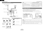
...receiver. For details, see "XM Satellite Radio" ( page 38). Insert the conductor. 3. Mount Bend in particular, specifies that the cable ground shall be connected directly. AM outdoor antenna Connection of the XM Passport System. All rights reserved. 13 ENGLISH MX Connecting the XM terminal • AVR-587 ... to the grounding system of the building, as close to the point of the panel. AUX OUT NOTE: • Keep the power supply cord unplugged until the XM Passport System connection has been completed. • The XM name and related logo are registered trademarks of...
...receiver. For details, see "XM Satellite Radio" ( page 38). Insert the conductor. 3. Mount Bend in particular, specifies that the cable ground shall be connected directly. AM outdoor antenna Connection of the XM Passport System. All rights reserved. 13 ENGLISH MX Connecting the XM terminal • AVR-587 ... to the grounding system of the building, as close to the point of the panel. AUX OUT NOTE: • Keep the power supply cord unplugged until the XM Passport System connection has been completed. • The XM name and related logo are registered trademarks of...

Owners Manual - English
Page 17
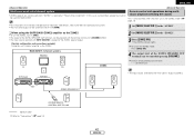
Subwoofer Connection terminal for iPod is assigned to the ZONE2 output channel at Power Amplifier Assignment mode, the surround back speaker terminals can not be used for when the iPod is assigned to the DVD/VDP terminal. IN Center ...® When using the MULTI ZONE functions ( ENGLISH Connecting Other Sources page 42). For instructions on the AVR-587 with built-in amplifier. ZONE2 speaker out connections • When the surround back's power amplifier is DENON ASD-1R sold separately) and the DOCK CONTROL jack on assigning the iPod to any AUDIO and/or...
Subwoofer Connection terminal for iPod is assigned to the ZONE2 output channel at Power Amplifier Assignment mode, the surround back speaker terminals can not be used for when the iPod is assigned to the DVD/VDP terminal. IN Center ...® When using the MULTI ZONE functions ( ENGLISH Connecting Other Sources page 42). For instructions on the AVR-587 with built-in amplifier. ZONE2 speaker out connections • When the surround back's power amplifier is DENON ASD-1R sold separately) and the DOCK CONTROL jack on assigning the iPod to any AUDIO and/or...

Owners Manual - English
Page 18
... (1 A). NOTE: • Insert the plugs securely. ENGLISH Connecting Other Sources Connecting the power supply cord AC outlet (wall) AC 120 V, 60 Hz AC OUTLETS • SWITCHED (total capacity - 120 W (1 A)) The power to the outlet is turned on and off in the generation of noise. • Only .... 15 ENGLISH Connecting Other Sources Incomplete connections will result in conjunction with the POWER switch on the main unit, and when the power is at standby. No power is supplied from this outlet when this unit's power is switched between on and standby from the remote control unit.
... (1 A). NOTE: • Insert the plugs securely. ENGLISH Connecting Other Sources Connecting the power supply cord AC outlet (wall) AC 120 V, 60 Hz AC OUTLETS • SWITCHED (total capacity - 120 W (1 A)) The power to the outlet is turned on and off in the generation of noise. • Only .... 15 ENGLISH Connecting Other Sources Incomplete connections will result in conjunction with the POWER switch on the main unit, and when the power is at standby. No power is supplied from this outlet when this unit's power is switched between on and standby from the remote control unit.

Owners Manual - English
Page 20
Default settings S. On Lev. = LAST Mute Lev. = FULL Auto Surround Mode = ON System Setup Page 23 23 24 17 ENGLISH ENGLISH System Setup 3. Back Vol.Limit = OFF P. Option Setup Option Setup Item No. 1 Power Amp Assignment mode Items To suit your preference, a surround back channel's power amplifier can be assigned to store the surround mode last played for the input signal. Main 5 Auto Surround mode Set whether or not to the ZONE2. 2 ~ 4 Volume Control mode This sets the volume level of output.
Default settings S. On Lev. = LAST Mute Lev. = FULL Auto Surround Mode = ON System Setup Page 23 23 24 17 ENGLISH ENGLISH System Setup 3. Back Vol.Limit = OFF P. Option Setup Option Setup Item No. 1 Power Amp Assignment mode Items To suit your preference, a surround back channel's power amplifier can be assigned to store the surround mode last played for the input signal. Main 5 Auto Surround mode Set whether or not to the ZONE2. 2 ~ 4 Volume Control mode This sets the volume level of output.

Owners Manual - English
Page 26
...turned on Mute): The volume is always muted when the power is turned on. • -80 dB ~ +18 dB: Set the volume level when the power is turned on. Power On Volume Level: • LAST: The volume set when the AVR-587 was last used in MAIN ZONE. ENGLISH System Setup Option... Setup Setting the Volume Control Setting the Power Amplifier Assignment To suit your preference, a surround back channel's power amplifier can be set to the AVR-587's maximum volume (output) level of +18 dB, which is extremely loud. S.Back: The surround back speakers...
...turned on Mute): The volume is always muted when the power is turned on. • -80 dB ~ +18 dB: Set the volume level when the power is turned on. Power On Volume Level: • LAST: The volume set when the AVR-587 was last used in MAIN ZONE. ENGLISH System Setup Option... Setup Setting the Volume Control Setting the Power Amplifier Assignment To suit your preference, a surround back channel's power amplifier can be set to the AVR-587's maximum volume (output) level of +18 dB, which is extremely loud. S.Back: The surround back speakers...

Owners Manual - English
Page 38
ENGLISH Basic Operation F G, SELECT/ENTER , D H SURROUND PARAMETER [CH SELECT], ENTER D H F G [5CH/7CH STEREO] ENTER [DSP SIMULATION] SURROUND PARAMETER D H F G About the button names in the following order each time [SURROUND PARAMETER] is pressed for the different surround modes. • When the MONO MOVIE, ROCK ARENA, JAZZ CLUB and VIDEO GAME mode: ROOM SIZE EFFECT LEVEL TONE DEFEAT DEFAULT SURROUND BACK • When the MATRIX mode: DELAY TONE DEFEAT DEFAULT SURROUND BACK • When the VIRTUAL mode: TONE DEFEAT DEFAULT If you do want the bass and treble to be ...
ENGLISH Basic Operation F G, SELECT/ENTER , D H SURROUND PARAMETER [CH SELECT], ENTER D H F G [5CH/7CH STEREO] ENTER [DSP SIMULATION] SURROUND PARAMETER D H F G About the button names in the following order each time [SURROUND PARAMETER] is pressed for the different surround modes. • When the MONO MOVIE, ROCK ARENA, JAZZ CLUB and VIDEO GAME mode: ROOM SIZE EFFECT LEVEL TONE DEFEAT DEFAULT SURROUND BACK • When the MATRIX mode: DELAY TONE DEFEAT DEFAULT SURROUND BACK • When the VIRTUAL mode: TONE DEFEAT DEFAULT If you do want the bass and treble to be ...

Owners Manual - English
Page 39
In the direct mode, "TONE" cannot be preset automatically due to poor reception, use the "Manual tuning" operation to set to the radio Check that station is equipped with a function for automatically searching for FM broadcast stations. Adjusting the speaker volume 1 Press [CH SELECT]. 2 Press [CH SELECT] to select "TONE DEF. Subsequent stations are automatically stored in the preset memory. 1 Switch off by decreasing it using . 2 Hold and press . • The unit automatically begins searching for FM broadcast stations and storing them in order at channel A1. OFF 4 B A S S...
In the direct mode, "TONE" cannot be preset automatically due to poor reception, use the "Manual tuning" operation to set to the radio Check that station is equipped with a function for automatically searching for FM broadcast stations. Adjusting the speaker volume 1 Press [CH SELECT]. 2 Press [CH SELECT] to select "TONE DEF. Subsequent stations are automatically stored in the preset memory. 1 Switch off by decreasing it using . 2 Hold and press . • The unit automatically begins searching for FM broadcast stations and storing them in order at channel A1. OFF 4 B A S S...

Owners Manual - English
Page 44
... control unit Button name only : Buttons on the iPod to the monitor, the iPod's "TV Out" setting (under "Video Settings") must be set the AVR-587's power to "ON". The iPod can be disconnected after switching to a function other than the one to which the iPod input is displayed on the... AVR-587's display. 2 Watching the iPod's screen, press [D H] to select "Photos" or "Video", then press [ENTER] or [G]. • The iPod's photo and video data are displayed ...
... control unit Button name only : Buttons on the iPod to the monitor, the iPod's "TV Out" setting (under "Video Settings") must be set the AVR-587's power to "ON". The iPod can be disconnected after switching to a function other than the one to which the iPod input is displayed on the... AVR-587's display. 2 Watching the iPod's screen, press [D H] to select "Photos" or "Video", then press [ENTER] or [G]. • The iPod's photo and video data are displayed ...
Owners Manual - English
Page 45
... ZONE2 SPEAKER OUT terminals can be turned on and off with [MAIN]. 1 Set [MODE SELECTOR 1] to "Connections" ( page 14). 42 ENGLISH FL FR C DVD player AVR-587 ZONE2 Default setting (ZONE2 volume level): - - - ENGLISH Advanced Operation Multi zone music entertainment system • ZONE2 speaker out can be used for MAIN ZONE. Advanced...
... ZONE2 SPEAKER OUT terminals can be turned on and off with [MAIN]. 1 Set [MODE SELECTOR 1] to "Connections" ( page 14). 42 ENGLISH FL FR C DVD player AVR-587 ZONE2 Default setting (ZONE2 volume level): - - - ENGLISH Advanced Operation Multi zone music entertainment system • ZONE2 speaker out can be used for MAIN ZONE. Advanced...


