Literature/Product Sheet
Page 2
... Cross-Over Switching The AVR-2805 supports subwoofer cross-over frequencies: 40, 60, 80, 100, 120, 150, 200 and 250 Hz. DENON ELECTRONICS (USA), LLC....AVR-2805. • When listening to PCM based sources, DENON's waveform technology AL24 Processing brings out all the delicate nuances of the source material. • Hefty Power Transformer for Stable Supply of Power A huge power transformer has been connected...figures are power amp stage values. Depending on Movie mode: On DENON A/V receivers, this design allows the AVR-2805 to achieve high output power of 100 W for front A/V input...
... Cross-Over Switching The AVR-2805 supports subwoofer cross-over frequencies: 40, 60, 80, 100, 120, 150, 200 and 250 Hz. DENON ELECTRONICS (USA), LLC....AVR-2805. • When listening to PCM based sources, DENON's waveform technology AL24 Processing brings out all the delicate nuances of the source material. • Hefty Power Transformer for Stable Supply of Power A huge power transformer has been connected...figures are power amp stage values. Depending on Movie mode: On DENON A/V receivers, this design allows the AVR-2805 to achieve high output power of 100 W for front A/V input...
Owners Manual
Page 10
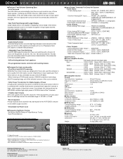
... lead terminals do not touch metal parts of multi-channel decoder, such as practical. Installation hole Mount on top any stable surface. Connection of the NEC which provides guidelines for inputting multi-channel audio signals from an outboard decoder, or a component with 8- a. Push ...75 Ω/ohms COAXIAL CABLE AM LOOP ANTENNA (Supplied) AM OUTDOOR ANTENNA AM loop antenna assembly 1 2 Connect to a wall. or 6-channel analog output 10 Front Surround Surround back Subwoofer Center R L R L RL For instructions on playback using the external input (EXT. Mount b. Note ...
... lead terminals do not touch metal parts of multi-channel decoder, such as practical. Installation hole Mount on top any stable surface. Connection of the NEC which provides guidelines for inputting multi-channel audio signals from an outboard decoder, or a component with 8- a. Push ...75 Ω/ohms COAXIAL CABLE AM LOOP ANTENNA (Supplied) AM OUTDOOR ANTENNA AM loop antenna assembly 1 2 Connect to a wall. or 6-channel analog output 10 Front Surround Surround back Subwoofer Center R L R L RL For instructions on playback using the external input (EXT. Mount b. Note ...
Owners Manual
Page 13
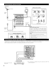
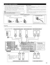
... be disturbed by the speaker's magnetism. If this effect. (L) (R) FRONT SPEAKER SYSTEMS (B) 13 Connections • When making connections, also refer to SURR. SURROUND SPEAKER SYSTEMS CENTER SPEAKER SYSTEM FRONT SPEAKER SYSTEMS (A) (L) (R) (L) (R) NOTES: • To use this speaker for subwoofer with built-in weak central sound, unclear orientation of the various instruments, and the...
... be disturbed by the speaker's magnetism. If this effect. (L) (R) FRONT SPEAKER SYSTEMS (B) 13 Connections • When making connections, also refer to SURR. SURROUND SPEAKER SYSTEMS CENTER SPEAKER SYSTEM FRONT SPEAKER SYSTEMS (A) (L) (R) (L) (R) NOTES: • To use this speaker for subwoofer with built-in weak central sound, unclear orientation of the various instruments, and the...
Owners Manual
Page 18
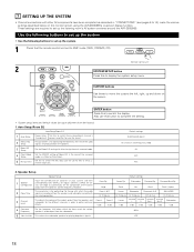
...complete the setting. • System setup items and default values (set up the listening room's AV system centered around the AVR-2805/985. Front Sp. Center Sp. Surround Back Sp. Large Small Yes Small Small / 2spkrs Front L & R Center Subwoofer Surround L & R SBL & SBR 12 ft (3.6 m) 12 ft (3.6 m) 12 ft ...speakers and the frequency response. 2 Delay Time This parameter is for optimizing the timing with other AV components have been completed as described in "CONNECTIONS" (see pages 6 to 14), make the various settings described below which the bass so ...
...complete the setting. • System setup items and default values (set up the listening room's AV system centered around the AVR-2805/985. Front Sp. Center Sp. Surround Back Sp. Large Small Yes Small Small / 2spkrs Front L & R Center Subwoofer Surround L & R SBL & SBR 12 ft (3.6 m) 12 ft (3.6 m) 12 ft ...speakers and the frequency response. 2 Delay Time This parameter is for optimizing the timing with other AV components have been completed as described in "CONNECTIONS" (see pages 6 to 14), make the various settings described below which the bass so ...
Owners Manual
Page 19
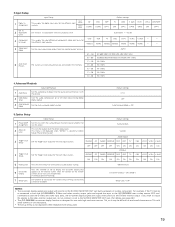
... Dolby Digital Setup Turn the audio compression on the remote control unit or main unit are received automatically and stored in the memory. AUX VCR-1 VCR-2 CDR/TAPE OFF OPT2 OPT5 OPT3.... • The setup menu is connected to both the AVR-2805/985's S-Video and video monitor output jacks and signals are input to the AVR-2805/985 from the monitor output terminal. Input...For example, if the TV monitor is not displayed when headphone are being used. 19 In 2 Subwoofer Level 3 Component In Assign Input Setup This assigns the digital input jacks for the different input sources....
... Dolby Digital Setup Turn the audio compression on the remote control unit or main unit are received automatically and stored in the memory. AUX VCR-1 VCR-2 CDR/TAPE OFF OPT2 OPT5 OPT3.... • The setup menu is connected to both the AVR-2805/985's S-Video and video monitor output jacks and signals are input to the AVR-2805/985 from the monitor output terminal. Input...For example, if the TV monitor is not displayed when headphone are being used. 19 In 2 Subwoofer Level 3 Component In Assign Input Setup This assigns the digital input jacks for the different input sources....

Owners Manual
Page 20
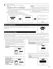
...system layout • The following is an example of the basic layout for a system consisting of eight speaker systems and a television monitor: Subwoofer Center speaker system Surround back speaker systems Front speaker systems Set these at the sides of the TV or screen with their front surfaces as...are correct, then turn on the main unit's power. Setup will not be possible when the unit is of a layered design that all the connections are plugged in System Setup, one level higher. 20 Therefore, please cancel the mode or reverse the condition. 2 Display the System Setup Menu. ...
...system layout • The following is an example of the basic layout for a system consisting of eight speaker systems and a television monitor: Subwoofer Center speaker system Surround back speaker systems Front speaker systems Set these at the sides of the TV or screen with their front surfaces as...are correct, then turn on the main unit's power. Setup will not be possible when the unit is of a layered design that all the connections are plugged in System Setup, one level higher. 20 Therefore, please cancel the mode or reverse the condition. 2 Display the System Setup Menu. ...
Owners Manual
Page 23
... automatic retry Remeasurement starts automatically to 2 times, and "Retry1" or "Retry2" is not connected, or when all of Auto Setup / Room EQ and the automatic measurements can adjust the ...properly detected. • Only one channel of the measurements. Remeasurement is performed to receive proper result of the pertinent speakers. About the error message These error screens will...will be displayed when accurate measurements cannot be displayed even though the speakers are completed. 2 Subwoofer speaker is measured twice. • Set the volume to halfway and set the crossover ...
... automatic retry Remeasurement starts automatically to 2 times, and "Retry1" or "Retry2" is not connected, or when all of Auto Setup / Room EQ and the automatic measurements can adjust the ...properly detected. • Only one channel of the measurements. Remeasurement is performed to receive proper result of the pertinent speakers. About the error message These error screens will...will be displayed when accurate measurements cannot be displayed even though the speakers are completed. 2 Subwoofer speaker is measured twice. • Set the volume to halfway and set the crossover ...
Owners Manual
Page 30
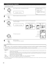
...for reproducing bass sound below . (Remote control unit) 3 Set whether speakers are installed. Yes/No Select "Yes" when a subwoofer is installed, "No" when a subwoofer is sent to the speaker's capacity for playing low frequency (bass sound below the frequency set for the front, center and ...surround speakers. 30 The Speaker Setup Menu reappears. Front Sp. Small Select this when no speakers are connected or not and, if ...
...for reproducing bass sound below . (Remote control unit) 3 Set whether speakers are installed. Yes/No Select "Yes" when a subwoofer is installed, "No" when a subwoofer is sent to the speaker's capacity for playing low frequency (bass sound below the frequency set for the front, center and ...surround speakers. 30 The Speaker Setup Menu reappears. Front Sp. Small Select this when no speakers are connected or not and, if ...
Owners Manual
Page 38
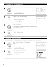
...(default) recommended. (0, +5, +10 or +15 can be selected.) (Remote control unit) 4 Enter the setting. In Subwoofer Level • Set the method of playback of the AVR-2805/985 for the different input sources. 1 Select "Component In Assign" at the Input Setup Menu. (Remote control unit) ... In Assign • This setting assigns the color difference (component) video input jacks of the analog input signal connected to the Ext.In Subwoofer. 1 Select "Ext.In Subwoofer Level" at the Input Setup Menu. (Remote control unit) *Input Setup Component In 2 Display the Component In...
...(default) recommended. (0, +5, +10 or +15 can be selected.) (Remote control unit) 4 Enter the setting. In Subwoofer Level • Set the method of playback of the AVR-2805/985 for the different input sources. 1 Select "Component In Assign" at the Input Setup Menu. (Remote control unit) ... In Assign • This setting assigns the color difference (component) video input jacks of the analog input signal connected to the Ext.In Subwoofer. 1 Select "Ext.In Subwoofer Level" at the Input Setup Menu. (Remote control unit) *Input Setup Component In 2 Display the Component In...

Owners Manual
Page 61
...watch video while listening to sound, select the input source to which the video signal is connected, then set this is selected, the input signals connected to these jacks cannot be set to the PRE OUT SUBWOOFER jack. 2 Cancelling the external input mode To cancel the external input (EXT. IN) ...mode. Press the EXT. In addition, the signal input to the SW (subwoofer) jack is set . 21 2 1 NOTES: • In play modes other than the external input mode, the signals connected to the FL (front left), FR (front right), C (center), SL (surround left), SR (surround...
...watch video while listening to sound, select the input source to which the video signal is connected, then set this is selected, the input signals connected to these jacks cannot be set to the PRE OUT SUBWOOFER jack. 2 Cancelling the external input mode To cancel the external input (EXT. IN) ...mode. Press the EXT. In addition, the signal input to the SW (subwoofer) jack is set . 21 2 1 NOTES: • In play modes other than the external input mode, the signals connected to the FL (front left), FR (front right), C (center), SL (surround left), SR (surround...


