Literature/Product Sheet
Page 1
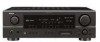
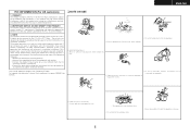
... be controlled via the remote controller supplied with the AVR-1507. *1) Supports 3rd-generation and later iPods equipped with DENON's DSP acoustic environment simulation modes. s XM Satellite Radio Ready with optional XM Passport System* (Supports XM 5.1ch surround powered by Neural Audio) *Subscription to Zone 2 speakers. A/V Receiver AVR-1507 DTS-ES Discrete 6.1 and Dolby Digital EX with...
... be controlled via the remote controller supplied with the AVR-1507. *1) Supports 3rd-generation and later iPods equipped with DENON's DSP acoustic environment simulation modes. s XM Satellite Radio Ready with optional XM Passport System* (Supports XM 5.1ch surround powered by Neural Audio) *Subscription to Zone 2 speakers. A/V Receiver AVR-1507 DTS-ES Discrete 6.1 and Dolby Digital EX with...
Literature/Product Sheet
Page 2
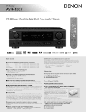
... and stereo video sources into exciting surround sound, free of delay effects and unnatural artifacts, from all of DENON's high-grade A/V receiver, the AVR-1507 lets you adjust parameters so that automatically remembers the surround mode you can customize the performance of Apple Computer,... - 107.9 MHz Usable sensitivity 1.0 µV (11.2 dBf) AM Section Tuning frequency range 520 - 1710 kHz Usable sensitivity 18 µV General Power supply AC 120 V, 60 Hz Power consumption 4.3 A Dimensions 17-3/32" (W) x 5-25/32" (H) x 16-9/64"(D) 434 (W) x 147 (H) x 417 (D) mm Weight 11...
... and stereo video sources into exciting surround sound, free of delay effects and unnatural artifacts, from all of DENON's high-grade A/V receiver, the AVR-1507 lets you adjust parameters so that automatically remembers the surround mode you can customize the performance of Apple Computer,... - 107.9 MHz Usable sensitivity 1.0 µV (11.2 dBf) AM Section Tuning frequency range 520 - 1710 kHz Usable sensitivity 18 µV General Power supply AC 120 V, 60 Hz Power consumption 4.3 A Dimensions 17-3/32" (W) x 5-25/32" (H) x 16-9/64"(D) 434 (W) x 147 (H) x 417 (D) mm Weight 11...
Owners Manual - English
Page 2
... by the operating instructions as contact with arrowhead symbol, within the product's enclosure that produce heat. Do not attempt to lightning and power-line surges. 17. Unplug this product yourself as radiators, heat registers, stoves, or other similar surface. this product near water -... to alert the user to the presence of antenna-discharge unit, connection to qualified service personnel under the following conditions: a) When the power-supply cord or plug is operated. 2. A product and cart combination should be placed in a built-in performance - This will often...
... by the operating instructions as contact with arrowhead symbol, within the product's enclosure that produce heat. Do not attempt to lightning and power-line surges. 17. Unplug this product yourself as radiators, heat registers, stoves, or other similar surface. this product near water -... to alert the user to the presence of antenna-discharge unit, connection to qualified service personnel under the following conditions: a) When the power-supply cord or plug is operated. 2. A product and cart combination should be placed in a built-in performance - This will often...
Owners Manual - English
Page 3
... installed as indicated in the instructions contained in a rack. Modification not expressly approved by DENON may not cause harmful interference, and (2) this product must accept any way. Allow for... the plug when unplugging the cord. * (For apparatuses with the apparatus. • Unplug the power cord when not using the apparatus for help. ¢NOTE ON USE • Do not let... operation. 2. However, there is no guarantee that interference will not occur in any interference received, including interference that to which can radiate radio frequency energy and, if not installed and ...
... installed as indicated in the instructions contained in a rack. Modification not expressly approved by DENON may not cause harmful interference, and (2) this product must accept any way. Allow for... the plug when unplugging the cord. * (For apparatuses with the apparatus. • Unplug the power cord when not using the apparatus for help. ¢NOTE ON USE • Do not let... operation. 2. However, there is no guarantee that interference will not occur in any interference received, including interference that to which can radiate radio frequency energy and, if not installed and ...
Owners Manual - English
Page 4
... As this manual before you begin hookup and operation that you for choosing the DENON AVR-1507 AV Surround Receiver. IN Subwoofer Level 22 Setting the Auto Preset Memory 22 Option Setup Setting the Power Amplifier Assignment 23 Setting the Volume Control 23 Setting the Auto Surround Mode 24 ...Logic II) mode 29 Selecting the DTS NEO:6 mode 30 Selecting the NEURAL SURROUND mode 30 Surround modes and parameters 31 ~ 33 Using the DENON original surround modes Types of the remote control unit 3 Part names and functions Front panel 4 Display 4 Rear panel 5 Remote control unit ...
... As this manual before you begin hookup and operation that you for choosing the DENON AVR-1507 AV Surround Receiver. IN Subwoofer Level 22 Setting the Auto Preset Memory 22 Option Setup Setting the Power Amplifier Assignment 23 Setting the Volume Control 23 Setting the Auto Surround Mode 24 ...Logic II) mode 29 Selecting the DTS NEO:6 mode 30 Selecting the NEURAL SURROUND mode 30 Surround modes and parameters 31 ~ 33 Using the DENON original surround modes Types of the remote control unit 3 Part names and functions Front panel 4 Display 4 Rear panel 5 Remote control unit ...
Owners Manual - English
Page 5
...43 Initialization of this manual 2 ENGLISH To prevent short-circuits or damaged wires in the connection cables, always unplug the power supply cord and disconnect the connection cables between all connections are correct and that the illustrations in these instructions in use.... explanation purposes. Troubleshooting 51 Specifications 52 List of preset codes End of the microprocessor (Reset 43 Operating the remote control unit Operating DENON audio components 44 Setting the preset memory function 44 Operating a component stored in the preset memory ····45 ...
...43 Initialization of this manual 2 ENGLISH To prevent short-circuits or damaged wires in the connection cables, always unplug the power supply cord and disconnect the connection cables between all connections are correct and that the illustrations in these instructions in use.... explanation purposes. Troubleshooting 51 Specifications 52 List of preset codes End of the microprocessor (Reset 43 Operating the remote control unit Operating DENON audio components 44 Setting the preset memory function 44 Operating a component stored in the preset memory ····45 ...
Owners Manual - English
Page 7
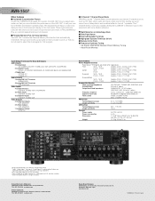
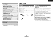
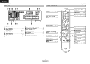
... @9 INPUT SELECTOR knob 25) Display uy t r t !2 q w e r y u i o !0 !1 !3 !4 !5 q w e q Power operation button (ON/STANDBY 9) w Power indicator 9) e Power switch 9, 43) r Headphones jack (PHONES 26) t ANALOG button 25) y SPEAKER buttons 9, 43) u ZONE2 button 42) i SHIFT button 37) ...o USER MODE buttons 39) !0 PRESET buttons 36, 37) !1 V. t STEREO indicator This lights when an FM stereo broadcast has been received...
... @9 INPUT SELECTOR knob 25) Display uy t r t !2 q w e r y u i o !0 !1 !3 !4 !5 q w e q Power operation button (ON/STANDBY 9) w Power indicator 9) e Power switch 9, 43) r Headphones jack (PHONES 26) t ANALOG button 25) y SPEAKER buttons 9, 43) u ZONE2 button 42) i SHIFT button 37) ...o USER MODE buttons 39) !0 PRESET buttons 36, 37) !1 V. t STEREO indicator This lights when an FM stereo broadcast has been received...
Owners Manual - English
Page 8
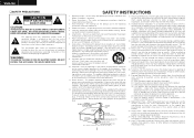
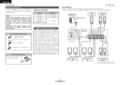
...t q PRE OUT terminal 7) w EXT. IN terminals 11) e DIGITAL terminals (Optical/Coaxial 8, 12) r AUDIO OUT terminals 8, 12) t Speaker terminals 7, 15) y Power supply cord 15) u AC outlets 15) i COMPONENT VIDEO terminals 8) o VIDEO/S-VIDEO terminals 8) !0 DOCK CONTROL jack 14) !1 AUDIO IN terminals 8) !2 XM terminal 13... buttons 28, 46) DISPLAY button 46) DIMMER/MENU button 26, 46) [ Front ] Getting Started Remote control signal transmitter 3) Power buttons 9, 46) Tuner system/System buttons 37, 38) Master volume control buttons 9, 25) MUTING button 26) NIGHT/AUDIO button 39...
...t q PRE OUT terminal 7) w EXT. IN terminals 11) e DIGITAL terminals (Optical/Coaxial 8, 12) r AUDIO OUT terminals 8, 12) t Speaker terminals 7, 15) y Power supply cord 15) u AC outlets 15) i COMPONENT VIDEO terminals 8) o VIDEO/S-VIDEO terminals 8) !0 DOCK CONTROL jack 14) !1 AUDIO IN terminals 8) !2 XM terminal 13... buttons 28, 46) DISPLAY button 46) DIMMER/MENU button 26, 46) [ Front ] Getting Started Remote control signal transmitter 3) Power buttons 9, 46) Tuner system/System buttons 37, 38) Master volume control buttons 9, 25) MUTING button 26) NIGHT/AUDIO button 39...
Owners Manual - English
Page 10
...ventilation around the unit. Loosen by turning clockwise. Insert the cable. 3. Easy Operation ¢ Connections • With the AVR-1507, up to the speakers is activated again even though there are matched (< with with >). Doing so could cause the ...activating the protection circuit. Connecting the speaker cables 1. Tighten by turning counterclockwise. If the protection circuit is cut off the power and contact a DENON service center. Connecting banana plugs Turn clockwise to tighten, then insert the banana plug. ¢ Speaker impedance Speaker Front...
...ventilation around the unit. Loosen by turning clockwise. Insert the cable. 3. Easy Operation ¢ Connections • With the AVR-1507, up to the speakers is activated again even though there are matched (< with with >). Doing so could cause the ...activating the protection circuit. Connecting the speaker cables 1. Tighten by turning counterclockwise. If the protection circuit is cut off the power and contact a DENON service center. Connecting banana plugs Turn clockwise to tighten, then insert the banana plug. ¢ Speaker impedance Speaker Front...

Owners Manual - English
Page 12
...'s manual. 4 Use VOLUME to the maximum or Low pass filter off . 4 Press or [ON/SOURCE]. • The power indicator blinks green and the power turns on the main unit and remote control unit 9 ENGLISH INPUT SELECTOR INPUT MODE About the button names in this function off before... performing the Auto Setup procedure. 2 Turn on your monitor. 3 Press . ¢ ON: The power indicator lights red. £ OFF: The power turns off and the indicator is displayed on the selected component. Some subwoofers have a standby mode. IN ANALOG Press to select ...
...'s manual. 4 Use VOLUME to the maximum or Low pass filter off . 4 Press or [ON/SOURCE]. • The power indicator blinks green and the power turns on the main unit and remote control unit 9 ENGLISH INPUT SELECTOR INPUT MODE About the button names in this function off before... performing the Auto Setup procedure. 2 Turn on your monitor. 3 Press . ¢ ON: The power indicator lights red. £ OFF: The power turns off and the indicator is displayed on the selected component. Some subwoofers have a standby mode. IN ANALOG Press to select ...
Owners Manual - English
Page 13
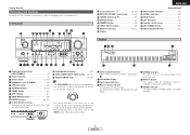
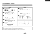
... completed. • When making connections, also refer to connect the left and right channels properly (left with left, right with right). • Do not bundle power cords together with speaker cables. Audio cable A Analog connections (Stereo) (White) (Red) L L R R Pin-plug cable B Analog connections (Monaural, for subwoofer) Video cable F Video connections (Yellow...
... completed. • When making connections, also refer to connect the left and right channels properly (left with left, right with right). • Do not bundle power cords together with speaker cables. Audio cable A Analog connections (Stereo) (White) (Red) L L R R Pin-plug cable B Analog connections (Monaural, for subwoofer) Video cable F Video connections (Yellow...
Owners Manual - English
Page 16
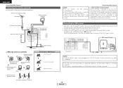
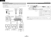
...With the antenna attached to the point of the panel. Connecting Other Sources Note to CATV system installer: This reminder is the XM Ready® receiver. Return the lever. All rights reserved. • XM Ready is used, do not disconnect the AM loop antenna. • Make sure the...(Supplied) Connecting the XM terminal • AVR-1507 is provided to call the CATV system installer's attention to Article 820-40 of XM Satellite Radio Inc. When making connections, also refer to receive the best signal. AUX OUT NOTE: • Keep the power supply cord unplugged until the XM Passport System...
...With the antenna attached to the point of the panel. Connecting Other Sources Note to CATV system installer: This reminder is the XM Ready® receiver. Return the lever. All rights reserved. • XM Ready is used, do not disconnect the AM loop antenna. • Make sure the...(Supplied) Connecting the XM terminal • AVR-1507 is provided to call the CATV system installer's attention to Article 820-40 of XM Satellite Radio Inc. When making connections, also refer to receive the best signal. AUX OUT NOTE: • Keep the power supply cord unplugged until the XM Passport System...
Owners Manual - English
Page 18
...when the surround back speaker is turned on the main unit, and when the power is at Power Amplifier Assignment mode, the surround back speaker terminals can not be used for audio equipment. No power is supplied from the remote control unit. Never use the AC OUTLETS for MAIN... ZONE. Never connect equipment whose total power consumption exceeds 120 W (1A.). Subwoofer Connection terminal for subwoofer with the POWER switch on and off in conjunction with built-in the generation of noise. • Only use it...
...when the surround back speaker is turned on the main unit, and when the power is at Power Amplifier Assignment mode, the surround back speaker terminals can not be used for audio equipment. No power is supplied from the remote control unit. Never use the AC OUTLETS for MAIN... ZONE. Never connect equipment whose total power consumption exceeds 120 W (1A.). Subwoofer Connection terminal for subwoofer with the POWER switch on and off in conjunction with built-in the generation of noise. • Only use it...
Owners Manual - English
Page 20
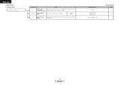
Option Setup Option Setup Item No. 1 Power Amp Assignment mode Items To suit your preference, a surround back channel's power amplifier can be assigned to store the surround mode last played for the input signal. Back Vol.Limit = OFF P. Default settings S. On Lev. = LAST Mute Lev. = FULL Auto Surround Mode = ON System Setup Page 23 23 24 17 ENGLISH Main 5 Auto Surround mode Set whether or not to the ZONE2. 2 ~ 4 Volume Control mode This sets the volume level of output. ENGLISH System Setup 3.
Option Setup Option Setup Item No. 1 Power Amp Assignment mode Items To suit your preference, a surround back channel's power amplifier can be assigned to store the surround mode last played for the input signal. Back Vol.Limit = OFF P. Default settings S. On Lev. = LAST Mute Lev. = FULL Auto Surround Mode = ON System Setup Page 23 23 24 17 ENGLISH Main 5 Auto Surround mode Set whether or not to the ZONE2. 2 ~ 4 Volume Control mode This sets the volume level of output. ENGLISH System Setup 3.
Owners Manual - English
Page 26
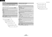
... back speaker terminals. 3 Press ENTER or H to enter the setting and switch to select "3. ON System Setup 23 ENGLISH Power On Volume Level: • LAST: The volume set when the AVR-1507 was last used in the memory and set a volume limit, select "OFF". Muting Level: Set the level of -70 ... speakers are used is stored in MAIN ZONE. In this case, the volume can be set . Op", then press ENTER. 2 Press F G to set to the AVR-1507's maximum volume (output) level of output. 1 Press D H to select the item, then press F G to +18 dB). ZONE2: This mode assigns the surround back ...
... back speaker terminals. 3 Press ENTER or H to enter the setting and switch to select "3. ON System Setup 23 ENGLISH Power On Volume Level: • LAST: The volume set when the AVR-1507 was last used in the memory and set a volume limit, select "OFF". Muting Level: Set the level of -70 ... speakers are used is stored in MAIN ZONE. In this case, the volume can be set . Op", then press ENTER. 2 Press F G to set to the AVR-1507's maximum volume (output) level of output. 1 Press D H to select the item, then press F G to +18 dB). ZONE2: This mode assigns the surround back ...
Owners Manual - English
Page 38
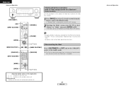
ENGLISH Basic Operation F G, SELECT/ENTER , D H SURROUND PARAMETER [CH SELECT], ENTER D H F G [5CH/7CH STEREO] ENTER [DSP SIMULATION] SURROUND PARAMETER D H F G About the button names in this explanation < > : Buttons on the main unit [ ] : Buttons on the remote control unit Button name only : Buttons on the main unit and remote control unit Selecting the DSP surround simulation ¢ To operate the surround mode and the surround parameters from the main unit's panel 1 Use to 4 under "Selecting the DSP surround simulation". 35 ENGLISH The surround parameter switches in ...
ENGLISH Basic Operation F G, SELECT/ENTER , D H SURROUND PARAMETER [CH SELECT], ENTER D H F G [5CH/7CH STEREO] ENTER [DSP SIMULATION] SURROUND PARAMETER D H F G About the button names in this explanation < > : Buttons on the main unit [ ] : Buttons on the remote control unit Button name only : Buttons on the main unit and remote control unit Selecting the DSP surround simulation ¢ To operate the surround mode and the surround parameters from the main unit's panel 1 Use to 4 under "Selecting the DSP surround simulation". 35 ENGLISH The surround parameter switches in ...
Owners Manual - English
Page 39
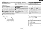
Adjusting the speaker volume 1 Press [CH SELECT]. 2 Press [CH SELECT] to set to tune in after the auto preset memory operation is tuned in the station, then preset it one step from -12.0 dB. ON 3 TONE DEF. Auto preset memory This unit is stored in the preset memory at step 3 in order at preset channels A1 to A8, B1 to B8, C1 to C8, D1 to D8, E1 to E8, F1 to F8 and G1 to "ON" at channel A1. In the direct mode, "TONE" cannot be turned off the unit using the manual "Preset memory" operation. • To interrupt this button is set the level. The SW channel level can be...
Adjusting the speaker volume 1 Press [CH SELECT]. 2 Press [CH SELECT] to set to tune in after the auto preset memory operation is tuned in the station, then preset it one step from -12.0 dB. ON 3 TONE DEF. Auto preset memory This unit is stored in the preset memory at step 3 in order at preset channels A1 to A8, B1 to B8, C1 to C8, D1 to D8, E1 to E8, F1 to F8 and G1 to "ON" at channel A1. In the direct mode, "TONE" cannot be turned off the unit using the manual "Preset memory" operation. • To interrupt this button is set the level. The SW channel level can be...
Owners Manual - English
Page 44
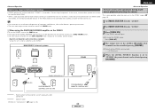
The iPod can be set the AVR-1507's power to the standby mode. ENGLISH Advanced Operation [OFF] [INPUT SELECTOR] [ENTER] [MODE SELECTOR 1] [ZONE2 OFF] [INPUT SELECTOR] [CHANNEL] Viewing still pictures and videos (only for ... Out" setting (under "Video Settings") must be disconnected after switching to a function other than the one to which the iPod input is displayed on the AVR-1507's display. 2 Watching the iPod's screen, press [D H] to select "Photos" or "Video", then press [ENTER] or [G]. • The iPod's photo and video data are displayed on...
The iPod can be set the AVR-1507's power to the standby mode. ENGLISH Advanced Operation [OFF] [INPUT SELECTOR] [ENTER] [MODE SELECTOR 1] [ZONE2 OFF] [INPUT SELECTOR] [CHANNEL] Viewing still pictures and videos (only for ... Out" setting (under "Video Settings") must be disconnected after switching to a function other than the one to which the iPod input is displayed on the AVR-1507's display. 2 Watching the iPod's screen, press [D H] to select "Photos" or "Video", then press [ENTER] or [G]. • The iPod's photo and video data are displayed on...
Owners Manual - English
Page 45
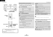
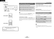
...setting (ZONE2 volume level): - - - In this unit's internal amplifier as the ZONE2. DVD player B AVR-1507 Input SW ZONE2 SPEAKER OUT RC-617 SL RC-616 SR SYSTEM REMOTE CONTROL UNIT RC-1048 : Room-...to-room remote control system (separately sold separately room-to-room remote control unit (DENON RC-616, 617 or 618) is output for MAIN ZONE. • When a sold ) ... Operation Remote control unit operations during multisource playback (selecting the source) This is selected at "Power Amp Assignment". dB (Minimum) FL FR C ZONE2 5 When the ZONE2 SOURCE function is ...
...setting (ZONE2 volume level): - - - In this unit's internal amplifier as the ZONE2. DVD player B AVR-1507 Input SW ZONE2 SPEAKER OUT RC-617 SL RC-616 SR SYSTEM REMOTE CONTROL UNIT RC-1048 : Room-...to-room remote control system (separately sold separately room-to-room remote control unit (DENON RC-616, 617 or 618) is output for MAIN ZONE. • When a sold ) ... Operation Remote control unit operations during multisource playback (selecting the source) This is selected at "Power Amp Assignment". dB (Minimum) FL FR C ZONE2 5 When the ZONE2 SOURCE function is ...
Owners Manual - English
Page 46
... IN's signal selected with INPUT SELECTOR are reset to the default values (the values set when the AVR-1507's power is switched to standby are stored in the memory for about 1 week, even when the power is turned off the unit using . 2 Keep both (A and B) depressed and turn on the ... Select the input source to be played. 2 Select the input mode and play (surround) mode. 3 Start recording on , the settings made when the power was switched to standby are recalled. ¢ Backup memory The various settings are stored in the memory. For instructions, refer to the audio output terminals...
... IN's signal selected with INPUT SELECTOR are reset to the default values (the values set when the AVR-1507's power is switched to standby are stored in the memory for about 1 week, even when the power is turned off the unit using . 2 Keep both (A and B) depressed and turn on the ... Select the input source to be played. 2 Select the input mode and play (surround) mode. 3 Start recording on , the settings made when the power was switched to standby are recalled. ¢ Backup memory The various settings are stored in the memory. For instructions, refer to the audio output terminals...


