
Getting Started Guide
Page 5
...drives or two optional 3.5-inch, internal SAS hard drives. (An optional SAS controller card is 1600x1200 with 65,536 colors. • Systems management circuitry that monitors operation of the system fans as well as critical system voltages and temperatures. • Back-panel connectors including...MHz PCI-X half-length expansion slot. A riser card supporting one x8 lane-width PCI-Express (PCIe) half-length expansion slot. This optional SAS controller also supports RAID levels 0 and 1.) • An optional slimline IDE optical drive. • An optional external USB diskette drive. •...
...drives or two optional 3.5-inch, internal SAS hard drives. (An optional SAS controller card is 1600x1200 with 65,536 colors. • Systems management circuitry that monitors operation of the system fans as well as critical system voltages and temperatures. • Back-panel connectors including...MHz PCI-X half-length expansion slot. A riser card supporting one x8 lane-width PCI-Express (PCIe) half-length expansion slot. This optional SAS controller also supports RAID levels 0 and 1.) • An optional slimline IDE optical drive. • An optional external USB diskette drive. •...
Hardware Owner's Manual
Page 4
Disabling a Forgotten Password 33 Baseboard Management Controller Configuration 33 Entering the BMC Setup Module 34 BMC Setup Module Options 34 3 Installing System Components 35 Recommended Tools 35 Inside the System 36 Removing ... the System 38 Closing the System 39 Cooling Shroud 39 Removing the Cooling Shroud 39 Replacing the Cooling Shroud 40 Cooling Fan Modules 40 Removing a Cooling Fan Module 40 Replacing a Cooling Fan Module 41 Power Supply 42 Removing the Power Supply 42 Installing the Power Supply 43 Expansion Cards 44 Installing an Expansion...
Disabling a Forgotten Password 33 Baseboard Management Controller Configuration 33 Entering the BMC Setup Module 34 BMC Setup Module Options 34 3 Installing System Components 35 Recommended Tools 35 Inside the System 36 Removing ... the System 38 Closing the System 39 Cooling Shroud 39 Removing the Cooling Shroud 39 Replacing the Cooling Shroud 40 Cooling Fan Modules 40 Removing a Cooling Fan Module 40 Replacing a Cooling Fan Module 41 Power Supply 42 Removing the Power Supply 42 Installing the Power Supply 43 Expansion Cards 44 Installing an Expansion...

Hardware Owner's Manual
Page 6
... Supply 74 Troubleshooting System Cooling Problems 75 Troubleshooting a Fan 75 Troubleshooting System Memory 76 Troubleshooting an Optical Drive 78 Troubleshooting a Hard Drive 78 Troubleshooting a SAS RAID Controller Card 79 Troubleshooting an Expansion Card 80 Troubleshooting the Microprocessors 82 5 Running the System Diagnostics 85 Using Dell PowerEdge Diagnostics 85 System Diagnostics Features 85 When to...
... Supply 74 Troubleshooting System Cooling Problems 75 Troubleshooting a Fan 75 Troubleshooting System Memory 76 Troubleshooting an Optical Drive 78 Troubleshooting a Hard Drive 78 Troubleshooting a SAS RAID Controller Card 79 Troubleshooting an Expansion Card 80 Troubleshooting the Microprocessors 82 5 Running the System Diagnostics 85 Using Dell PowerEdge Diagnostics 85 System Diagnostics Features 85 When to...

Hardware Owner's Manual
Page 35
...; Front bezel • System cover • Cooling shroud • Cooling fan modules • Power supply • Expansion cards • System memory • Processors • Optical drive • Hard drives • Boot drive • SAS controller card • System battery • Risers • Control panel assembly • System board Recommended Tools You may need...
...; Front bezel • System cover • Cooling shroud • Cooling fan modules • Power supply • Expansion cards • System memory • Processors • Optical drive • Hard drives • Boot drive • SAS controller card • System battery • Risers • Control panel assembly • System board Recommended Tools You may need...

Hardware Owner's Manual
Page 63
... Allow time for complete information about safety precautions, working inside the system. See "Removing Memory Modules" on page 58. 6 Disconnect the two fan module power cables from the system board. See "Opening and Closing the System" on page 42. 8 If applicable, disconnect the optical drive ...out of the chassis. b While pulling the release pin, slide the system-board tray toward the front of the socket. 9 Disconnect the control panel cable from the chassis. NOTE: While removing the memory modules, record the memory module socket locations to cool before handling them. See ...
... Allow time for complete information about safety precautions, working inside the system. See "Removing Memory Modules" on page 58. 6 Disconnect the two fan module power cables from the system board. See "Opening and Closing the System" on page 42. 8 If applicable, disconnect the optical drive ...out of the chassis. b While pulling the release pin, slide the system-board tray toward the front of the socket. 9 Disconnect the control panel cable from the chassis. NOTE: While removing the memory modules, record the memory module socket locations to cool before handling them. See ...

Hardware Owner's Manual
Page 64
...system board attached to the system board. See Figure 6-2. 7 Reinstall the power supply. See "Removing and Installing a Cooling Fan Module" on page 44. 10 Reconnect the two fan module power cables to the system board. See Figure 6-2. 6 If applicable, connect the optical drive cable to system-board ... 43. 8 Replace the riser board. See "Installing Memory Modules" on page 48. 3 Lower the system-board tray into position. 5 Connect the control panel cable to the system board. See "Installing a Processor" on the bottom of the chassis. 4 Slide the system-board tray toward the back of...
...system board attached to the system board. See Figure 6-2. 7 Reinstall the power supply. See "Removing and Installing a Cooling Fan Module" on page 44. 10 Reconnect the two fan module power cables to the system board. See Figure 6-2. 6 If applicable, connect the optical drive cable to system-board ... 43. 8 Replace the riser board. See "Installing Memory Modules" on page 48. 3 Lower the system-board tray into position. 5 Connect the control panel cable to the system board. See "Installing a Processor" on the bottom of the chassis. 4 Slide the system-board tray toward the back of...
Hardware Owner's Manual
Page 93
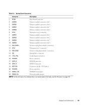
... 2 9 DIMM3 Memory module connector, slot 3 10 DIMM4 Memory module connector, slot 4 11 FAN_MOD2 System cooling fan module 2 connector 12 CPU1 Microprocessor 1 connector 13 FAN_MOD1 System cooling fan module 1 connector 14 IDE Optical drive connector 15 CTRL_PNL Control panel connector 16 POWER1 Power connector 17 SATA_B SATA B connector 18 SATA_A SATA A connector 19 BATTERY...
... 2 9 DIMM3 Memory module connector, slot 3 10 DIMM4 Memory module connector, slot 4 11 FAN_MOD2 System cooling fan module 2 connector 12 CPU1 Microprocessor 1 connector 13 FAN_MOD1 System cooling fan module 1 connector 14 IDE Optical drive connector 15 CTRL_PNL Control panel connector 16 POWER1 Power connector 17 SATA_B SATA B connector 18 SATA_A SATA A connector 19 BATTERY...
Hardware Owner's Manual
Page 121
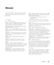
... instructions for communications between the processor and peripheral devices • Miscellaneous functions, such as system messages bit - Baseboard management controller. Unless the operating system fails to the system. bootable diskette - A standard interface for Information Interchange. A battery that is...Celsius. Glossary 121 Your system's BIOS contains programs stored on . Your system contains an expansion bus that includes power supplies and fans. bus - A fast storage area that contains a processor, memory, and a hard drive. American National Standards Institute. A ...
... instructions for communications between the processor and peripheral devices • Miscellaneous functions, such as system messages bit - Baseboard management controller. Unless the operating system fails to the system. bootable diskette - A standard interface for Information Interchange. A battery that is...Celsius. Glossary 121 Your system's BIOS contains programs stored on . Your system contains an expansion bus that includes power supplies and fans. bus - A fast storage area that contains a processor, memory, and a hard drive. American National Standards Institute. A ...
Hardware Owner's Manual
Page 129
...alert messages, 22 B back-panel features, 13 baseboard management controller. battery replacing, 59 troubleshooting, 74 bezel removing, 37 replacing, 37 BMC configuration, 33 setup module, 10 boot device configuring, 57 cooling fan modules removing, 40 replacing, 41 troubleshooting, 75 cooling shroud ...removing, 39 replacing, 40 cover closing, 39 opening, 38 D Dell contacting, 99-100 diagnostic messages, 22 diagnostics advanced testing options, ...
...alert messages, 22 B back-panel features, 13 baseboard management controller. battery replacing, 59 troubleshooting, 74 bezel removing, 37 replacing, 37 BMC configuration, 33 setup module, 10 boot device configuring, 57 cooling fan modules removing, 40 replacing, 41 troubleshooting, 75 cooling shroud ...removing, 39 replacing, 40 cover closing, 39 opening, 38 D Dell contacting, 99-100 diagnostic messages, 22 diagnostics advanced testing options, ...

Hardware Owner's Manual
Page 130
I indicators back-panel, 13 front-panel, 11 NIC, 14 power, 13 installing control panel assembly, 62 expansion card, 44 expansion-card riser board, 59 memory modules, 48 optical drive, 54 processor, 50, 52 SAS/SATA hard drives, 56 ... troubleshooting, 74 PowerNow!, 28 processor installing, 52 replacing, 50 troubleshooting, 82 upgrades, 50 PXE boot entering, 10 R RAID controller installing, 56 troubleshooting, 79 recommended tools, 35 removing bezel, 37 control panel assembly, 61 cooling fan module, 40 cover, 38 expansion card, 45 expansion-card riser board, 58 memory modules, 49 optical drive, 54...
I indicators back-panel, 13 front-panel, 11 NIC, 14 power, 13 installing control panel assembly, 62 expansion card, 44 expansion-card riser board, 59 memory modules, 48 optical drive, 54 processor, 50, 52 SAS/SATA hard drives, 56 ... troubleshooting, 74 PowerNow!, 28 processor installing, 52 replacing, 50 troubleshooting, 82 upgrades, 50 PXE boot entering, 10 R RAID controller installing, 56 troubleshooting, 79 recommended tools, 35 removing bezel, 37 control panel assembly, 61 cooling fan module, 40 cover, 38 expansion card, 45 expansion-card riser board, 58 memory modules, 49 optical drive, 54...

Hardware Owner's Manual
Page 131
...fan module, 41 power supply, 43 processor, 50 system battery, 59 S safety, 67 SAS configuration utility entering, 10 SAS hard drives, 55 SAS RAID controller installing, 56 troubleshooting, 79 SATA hard drives, 55 serial I/O device troubleshooting, 71 setup password, 30 assigning, 32 changing, 33 enabling, 32 startup keystrokes, 10 support contacting Dell... troubleshooting (continued) mouse, 70 NIC, 72 optical drive, 78 power problems, 68 power supply, 74 processor, 82 RAID controller, 79 serial I/O device, 71 start-up routine, 67 system battery, 74 system cooling problems, 75 USB device, 71 ...
...fan module, 41 power supply, 43 processor, 50 system battery, 59 S safety, 67 SAS configuration utility entering, 10 SAS hard drives, 55 SAS RAID controller installing, 56 troubleshooting, 79 SATA hard drives, 55 serial I/O device troubleshooting, 71 setup password, 30 assigning, 32 changing, 33 enabling, 32 startup keystrokes, 10 support contacting Dell... troubleshooting (continued) mouse, 70 NIC, 72 optical drive, 78 power problems, 68 power supply, 74 processor, 82 RAID controller, 79 serial I/O device, 71 start-up routine, 67 system battery, 74 system cooling problems, 75 USB device, 71 ...


