
Getting Started Guide
Page 5
... An optional slimline IDE optical drive. • An optional external USB diskette drive. • A 600-W power supply. • Four dual-rotor fan modules. This PCI-X slot also supports legacy PCI expansion cards. • Two integrated Gb Ethernet NICs, capable of supporting 10-Mbps, 100-Mbps,...drives. (An optional SAS controller card is 1600x1200 with 65,536 colors. • Systems management circuitry that monitors operation of the system fans as well as critical system voltages and temperatures. • Back-panel connectors including serial, video, two USB connectors, and two NIC ...
... An optional slimline IDE optical drive. • An optional external USB diskette drive. • A 600-W power supply. • Four dual-rotor fan modules. This PCI-X slot also supports legacy PCI expansion cards. • Two integrated Gb Ethernet NICs, capable of supporting 10-Mbps, 100-Mbps,...drives. (An optional SAS controller card is 1600x1200 with 65,536 colors. • Systems management circuitry that monitors operation of the system fans as well as critical system voltages and temperatures. • Back-panel connectors including serial, video, two USB connectors, and two NIC ...
Hardware Owner's Manual
Page 4
... the System 38 Closing the System 39 Cooling Shroud 39 Removing the Cooling Shroud 39 Replacing the Cooling Shroud 40 Cooling Fan Modules 40 Removing a Cooling Fan Module 40 Replacing a Cooling Fan Module 41 Power Supply 42 Removing the Power Supply 42 Installing the Power Supply 43 Expansion Cards 44 Installing an Expansion...
... the System 38 Closing the System 39 Cooling Shroud 39 Removing the Cooling Shroud 39 Replacing the Cooling Shroud 40 Cooling Fan Modules 40 Removing a Cooling Fan Module 40 Replacing a Cooling Fan Module 41 Power Supply 42 Removing the Power Supply 42 Installing the Power Supply 43 Expansion Cards 44 Installing an Expansion...

Hardware Owner's Manual
Page 6
... 74 Troubleshooting System Cooling Problems 75 Troubleshooting a Fan 75 Troubleshooting System Memory 76 Troubleshooting an Optical Drive 78 Troubleshooting a Hard Drive 78 Troubleshooting a SAS RAID Controller Card 79 Troubleshooting an Expansion Card 80 Troubleshooting the Microprocessors 82 5 Running the System Diagnostics 85 Using Dell PowerEdge Diagnostics 85 System Diagnostics Features 85 When to...
... 74 Troubleshooting System Cooling Problems 75 Troubleshooting a Fan 75 Troubleshooting System Memory 76 Troubleshooting an Optical Drive 78 Troubleshooting a Hard Drive 78 Troubleshooting a SAS RAID Controller Card 79 Troubleshooting an Expansion Card 80 Troubleshooting the Microprocessors 82 5 Running the System Diagnostics 85 Using Dell PowerEdge Diagnostics 85 System Diagnostics Features 85 When to...
Hardware Owner's Manual
Page 22
... then follow the instructions in that you to respond before the system continues a task. Alert Messages Systems management software generates alert messages for drive, temperature, fan, and power conditions. Alert messages include information, status, warning, and failure messages for your system. For example, before you format a diskette, a message will warn you...
... then follow the instructions in that you to respond before the system continues a task. Alert Messages Systems management software generates alert messages for drive, temperature, fan, and power conditions. Alert messages include information, status, warning, and failure messages for your system. For example, before you format a diskette, a message will warn you...

Hardware Owner's Manual
Page 35
Installing System Components This section describes how to install the following system components: • Front bezel • System cover • Cooling shroud • Cooling fan modules • Power supply • Expansion cards • System memory • Processors • Optical drive • Hard drives • Boot drive • SAS controller card &#...
Installing System Components This section describes how to install the following system components: • Front bezel • System cover • Cooling shroud • Cooling fan modules • Power supply • Expansion cards • System memory • Processors • Optical drive • Hard drives • Boot drive • SAS controller card &#...
Hardware Owner's Manual
Page 36
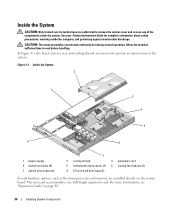
... information, see "Expansion Cards" on the system board. Inside the System 2 1 3 4 5 8 6 1 power supply 4 memory modules (8) 7 optical drive (optional) 7 2 cooling shroud 3 expansion card 5 heatsink/microprocessor (2) 6 cooling fan modules (2) 8 3.5-inch hard drive bays (2) Several hardware options, such as the microprocessors and memory, are installed directly on page 44. 36 Installing System Components The...
... information, see "Expansion Cards" on the system board. Inside the System 2 1 3 4 5 8 6 1 power supply 4 memory modules (8) 7 optical drive (optional) 7 2 cooling shroud 3 expansion card 5 heatsink/microprocessor (2) 6 cooling fan modules (2) 8 3.5-inch hard drive bays (2) Several hardware options, such as the microprocessors and memory, are installed directly on page 44. 36 Installing System Components The...
Hardware Owner's Manual
Page 40
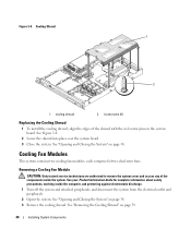
... into place over the system board. 3 Close the system. See "Removing the Cooling Shroud" on the system board. Cooling Fan Modules This system contains two cooling fan modules, each comprised of the components inside the computer, and protecting against electrostatic discharge. 1 Turn off the system and attached peripherals..., and disconnect the system from the electrical outlet and peripherals. 2 Open the system. Removing a Cooling Fan Module CAUTION: Only trained service technicians are authorized to remove the system cover and access any of two dual-rotor...
... into place over the system board. 3 Close the system. See "Removing the Cooling Shroud" on the system board. Cooling Fan Modules This system contains two cooling fan modules, each comprised of the components inside the computer, and protecting against electrostatic discharge. 1 Turn off the system and attached peripherals..., and disconnect the system from the electrical outlet and peripherals. 2 Open the system. Removing a Cooling Fan Module CAUTION: Only trained service technicians are authorized to remove the system cover and access any of two dual-rotor...
Hardware Owner's Manual
Page 41
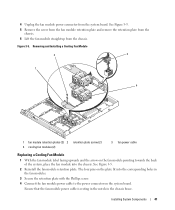
... power cable to the power connector on the fan module pointing towards the back of the system, place the fan module into the chassis. Removing and Installing a Cooling Fan Module 2 3 1 4 1 fan module retention plates (2) 2 4 cooling fan modules (2) retention plate screw (2) 3 fan power cable Replacing a Cooling Fan Module 1 With the fan module label facing upwards and the arrow on...
... power cable to the power connector on the fan module pointing towards the back of the system, place the fan module into the chassis. Removing and Installing a Cooling Fan Module 2 3 1 4 1 fan module retention plates (2) 2 4 cooling fan modules (2) retention plate screw (2) 3 fan power cable Replacing a Cooling Fan Module 1 With the fan module label facing upwards and the arrow on...

Hardware Owner's Manual
Page 63
... cover and access any cables from the system board back panel. 4 Remove the cooling shroud. See "Removing Memory Modules" on page 58. 6 Disconnect the two fan module power cables from the system board. See your Product Information Guide for complete information about safety precautions, working inside the system. NOTE: While removing...
... cover and access any cables from the system board back panel. 4 Remove the cooling shroud. See "Removing Memory Modules" on page 58. 6 Disconnect the two fan module power cables from the system board. See your Product Information Guide for complete information about safety precautions, working inside the system. NOTE: While removing...

Hardware Owner's Manual
Page 64
See "Installing a Processor" on page 44. 10 Reconnect the two fan module power cables to the system board. Figure 3-16. System Board Removal 1 1 2 2 1 system board release pin 2 system board attached to the system board. See "Installing ... panel cable to the system board. See "Installing an Expansion-Card Riser" on page 41. 11 Replace the cooling shroud. See "Removing and Installing a Cooling Fan Module" on page 59. 9 Replace any expansion card(s). See "Installing the Power Supply" on page 43. 8 Replace the riser board.
See "Installing a Processor" on page 44. 10 Reconnect the two fan module power cables to the system board. Figure 3-16. System Board Removal 1 1 2 2 1 system board release pin 2 system board attached to the system board. See "Installing ... panel cable to the system board. See "Installing an Expansion-Card Riser" on page 41. 11 Replace the cooling shroud. See "Removing and Installing a Cooling Fan Module" on page 59. 9 Replace any expansion card(s). See "Installing the Power Supply" on page 43. 8 Replace the riser board.
Hardware Owner's Manual
Page 73
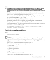
... for complete information about safety precautions, working inside the computer and protecting against electrostatic discharge. 1 Open the system. See "Using Dell PowerEdge Diagnostics" on page 38. 2 Ensure that the following components are properly installed: • Cooling shroud • Expansion card and... riser • Processor(s) and heatsink(s) • Memory modules • Fans 3 Ensure that you removed. See "Opening and Closing the System" on the system and attached peripherals. See "Opening and Closing...
... for complete information about safety precautions, working inside the computer and protecting against electrostatic discharge. 1 Open the system. See "Using Dell PowerEdge Diagnostics" on page 38. 2 Ensure that the following components are properly installed: • Cooling shroud • Expansion card and... riser • Processor(s) and heatsink(s) • Memory modules • Fans 3 Ensure that you removed. See "Opening and Closing the System" on the system and attached peripherals. See "Opening and Closing...

Hardware Owner's Manual
Page 75
...is removed. • Ambient temperature is too high. • External airflow is not resolved, see ""Getting Help" on page 95." Troubleshooting a Fan Problem • System-status indicator is not blinking green and the system does not power up. 2 Replace the faulty power supply with a new ... on page 43. 4 Replace the power supply with a new power supply. See "Troubleshooting a Fan" on page 42. If the problem is obstructed. • Cables inside the system obstruct airflow. • A cooling fan has failed. See "Power Supply" on page 75. See "Power Supply" on page 42. 5...
...is removed. • Ambient temperature is too high. • External airflow is not resolved, see ""Getting Help" on page 95." Troubleshooting a Fan Problem • System-status indicator is not blinking green and the system does not power up. 2 Replace the faulty power supply with a new ... on page 43. 4 Replace the power supply with a new power supply. See "Troubleshooting a Fan" on page 42. If the problem is obstructed. • Cables inside the system obstruct airflow. • A cooling fan has failed. See "Power Supply" on page 75. See "Power Supply" on page 42. 5...
Hardware Owner's Manual
Page 76
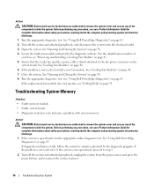
... and access any of the components inside the system. See "Opening and Closing the System" on page 38. 4 Locate the faulty fan module indicated by the diagnostic program. See "Using Dell PowerEdge Diagnostics" on page 40. 7 Close the system. See "Opening and Closing the System" on page 38. 8 Run the appropriate diagnostic test...
... and access any of the components inside the system. See "Opening and Closing the System" on page 38. 4 Locate the faulty fan module indicated by the diagnostic program. See "Using Dell PowerEdge Diagnostics" on page 40. 7 Close the system. See "Opening and Closing the System" on page 38. 8 Run the appropriate diagnostic test...
Hardware Owner's Manual
Page 93
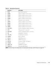
... 1 8 DIMM2 Memory module connector, slot 2 9 DIMM3 Memory module connector, slot 3 10 DIMM4 Memory module connector, slot 4 11 FAN_MOD2 System cooling fan module 2 connector 12 CPU1 Microprocessor 1 connector 13 FAN_MOD1 System cooling fan module 1 connector 14 IDE Optical drive connector 15 CTRL_PNL Control panel connector 16 POWER1 Power connector 17 SATA_B SATA B connector...
... 1 8 DIMM2 Memory module connector, slot 2 9 DIMM3 Memory module connector, slot 3 10 DIMM4 Memory module connector, slot 4 11 FAN_MOD2 System cooling fan module 2 connector 12 CPU1 Microprocessor 1 connector 13 FAN_MOD1 System cooling fan module 1 connector 14 IDE Optical drive connector 15 CTRL_PNL Control panel connector 16 POWER1 Power connector 17 SATA_B SATA B connector...
Hardware Owner's Manual
Page 121
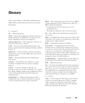
... used in a special section of your system, back up important start-up your system. Your system contains an expansion bus that includes power supplies and fans. A fast storage area that is located. A - Software designed to help you can retrieve the data from RAM faster than from the hard drive. American Standard...
... used in a special section of your system, back up important start-up your system. Your system contains an expansion bus that includes power supplies and fans. A fast storage area that is located. A - Software designed to help you can retrieve the data from RAM faster than from the hard drive. American Standard...
Hardware Owner's Manual
Page 129
..., 80 expansion-card riser board available options, 44 connectors, 94 installing, 59 PCI buses, 94 removing, 58 external devices connecting, 13 F fan modules, 40 front-panel features, 11 G guidelines for memory installation, 46 H hard drive (SAS/SATA) boot device, 57 installing, 56 ...37 BMC configuration, 33 setup module, 10 boot device configuring, 57 cooling fan modules removing, 40 replacing, 41 troubleshooting, 75 cooling shroud removing, 39 replacing, 40 cover closing, 39 opening, 38 D Dell contacting, 99-100 diagnostic messages, 22 diagnostics advanced testing options, 87 testing...
..., 80 expansion-card riser board available options, 44 connectors, 94 installing, 59 PCI buses, 94 removing, 58 external devices connecting, 13 F fan modules, 40 front-panel features, 11 G guidelines for memory installation, 46 H hard drive (SAS/SATA) boot device, 57 installing, 56 ...37 BMC configuration, 33 setup module, 10 boot device configuring, 57 cooling fan modules removing, 40 replacing, 41 troubleshooting, 75 cooling shroud removing, 39 replacing, 40 cover closing, 39 opening, 38 D Dell contacting, 99-100 diagnostic messages, 22 diagnostics advanced testing options, 87 testing...

Hardware Owner's Manual
Page 130
... troubleshooting, 82 upgrades, 50 PXE boot entering, 10 R RAID controller installing, 56 troubleshooting, 79 recommended tools, 35 removing bezel, 37 control panel assembly, 61 cooling fan module, 40 cover, 38 expansion card, 45 expansion-card riser board, 58 memory modules, 49 optical drive, 54 power supply, 42 system battery, 59 system...
... troubleshooting, 82 upgrades, 50 PXE boot entering, 10 R RAID controller installing, 56 troubleshooting, 79 recommended tools, 35 removing bezel, 37 control panel assembly, 61 cooling fan module, 40 cover, 38 expansion card, 45 expansion-card riser board, 58 memory modules, 49 optical drive, 54 power supply, 42 system battery, 59 system...

Hardware Owner's Manual
Page 131
...fan module, 41 power supply, 43 processor, 50 system battery, 59 S safety, 67 SAS configuration utility entering, 10 SAS hard drives, 55 SAS RAID controller installing, 56 troubleshooting, 79 SATA hard drives, 55 serial I/O device troubleshooting, 71 setup password, 30 assigning, 32 changing, 33 enabling, 32 startup keystrokes, 10 support contacting Dell..., 27 navigation keys, 24 options, 24 System Securtiy screen, 29 using, 24 T tools needed, 35 troubleshooting cooling fan modules, 75 damaged system, 73 equipment check, 68 expansion card, 80 external connections, 69 hard drive, 78 keyboard,...
...fan module, 41 power supply, 43 processor, 50 system battery, 59 S safety, 67 SAS configuration utility entering, 10 SAS hard drives, 55 SAS RAID controller installing, 56 troubleshooting, 79 SATA hard drives, 55 serial I/O device troubleshooting, 71 setup password, 30 assigning, 32 changing, 33 enabling, 32 startup keystrokes, 10 support contacting Dell..., 27 navigation keys, 24 options, 24 System Securtiy screen, 29 using, 24 T tools needed, 35 troubleshooting cooling fan modules, 75 damaged system, 73 equipment check, 68 expansion card, 80 external connections, 69 hard drive, 78 keyboard,...


