
Getting Started Guide
Page 5
... Started With Your System 3 A riser card supporting one 3.3-V, 64-bit, 133-MHz PCI-X half-length expansion slot. This optional SAS controller also supports RAID levels 0 and 1.) • An optional slimline IDE optical drive. • An optional external USB diskette drive. • A 600-W power supply. • Four dual-rotor fan modules. The video subsystem includes a minimum of 16 MB of the system fans as well as critical system voltages and temperatures. • Back-panel connectors...
... Started With Your System 3 A riser card supporting one 3.3-V, 64-bit, 133-MHz PCI-X half-length expansion slot. This optional SAS controller also supports RAID levels 0 and 1.) • An optional slimline IDE optical drive. • An optional external USB diskette drive. • A 600-W power supply. • Four dual-rotor fan modules. The video subsystem includes a minimum of 16 MB of the system fans as well as critical system voltages and temperatures. • Back-panel connectors...
Hardware Owner's Manual
Page 16
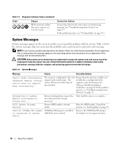
... against electrostatic discharge. Remote BIOS update attempt failed. is in a configuration that supports node interleaving. Corrective Action Ensure that the memory modules are disabled! CAUTION: Only trained service technicians are functioning properly. Table 1-6. Node Interleaving The memory configuration does not Ensure that all network connections are authorized to remove the system cover and access any of the message and recommended action. support node interleaving. NVRAM_CLR jumper NVRAM_CLR jumper is being processed...
... against electrostatic discharge. Remote BIOS update attempt failed. is in a configuration that supports node interleaving. Corrective Action Ensure that the memory modules are disabled! CAUTION: Only trained service technicians are functioning properly. Table 1-6. Node Interleaving The memory configuration does not Ensure that all network connections are authorized to remove the system cover and access any of the message and recommended action. support node interleaving. NVRAM_CLR jumper NVRAM_CLR jumper is being processed...
Hardware Owner's Manual
Page 17
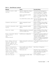
Remote configuration update attempt failed Fatal error caused a system reset: Please check the system event log for the specific cause, then see "Troubleshooting System Memory" on page 76. Faulty or improperly installed diskette drive. If the problem persists, see "Troubleshooting a USB Device" on page 71. Loose diskette drive interface cable. Faulty or improperly inserted diskette. If the problem inserted in a valid configuration. faulty system board. Check the system event log for details. Reconnect the diskette drive USB cable. If the problem persists...
Remote configuration update attempt failed Fatal error caused a system reset: Please check the system event log for the specific cause, then see "Troubleshooting System Memory" on page 76. Faulty or improperly installed diskette drive. If the problem persists, see "Troubleshooting a USB Device" on page 71. Loose diskette drive interface cable. Faulty or improperly inserted diskette. If the problem inserted in a valid configuration. faulty system board. Check the system event log for details. Reconnect the diskette drive USB cable. If the problem persists...
Hardware Owner's Manual
Page 19
..., install the operating system on your operating system documentation. See your hard drive. No timer tick interrupt Faulty system board. Reseat the PCIe card in the specified slot number. Reseat the PCIe card in the specified slot number. PCI BIOS failed to the expansion cards. Ensure checksum failure is n Faulty or improperly installed PCIe card in the specified slot. faulty system board. About Your System 19 See "Using the System Setup Program" on page 80. PCIe Degraded Link Width Error: Embedded Bus...
..., install the operating system on your operating system documentation. See your hard drive. No timer tick interrupt Faulty system board. Reseat the PCIe card in the specified slot number. Reseat the PCIe card in the specified slot number. PCI BIOS failed to the expansion cards. Ensure checksum failure is n Faulty or improperly installed PCIe card in the specified slot. faulty system board. About Your System 19 See "Using the System Setup Program" on page 80. PCIe Degraded Link Width Error: Embedded Bus...
Hardware Owner's Manual
Page 28
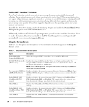
... Enabled without PXE default) Enables or disables the system's integrated NIC2. feature, run the System Setup Program and enable the Demand-Based Power Management option on this menu screen if your system.) To enable the PowerNow! driver to install the PowerNow! Table 2-5. Disabling the USB ports makes system resources available for NIC1. MAC Address Displays the MAC address for other devices. This field does not have user-selectable settings. 28 Using the System Setup Program Changes...
... Enabled without PXE default) Enables or disables the system's integrated NIC2. feature, run the System Setup Program and enable the Demand-Based Power Management option on this menu screen if your system.) To enable the PowerNow! driver to install the PowerNow! Table 2-5. Disabling the USB ports makes system resources available for NIC1. MAC Address Displays the MAC address for other devices. This field does not have user-selectable settings. 28 Using the System Setup Program Changes...
Hardware Owner's Manual
Page 29
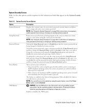
... System Password Setup Password Password Status Power Button NMI Button Description Displays the current status of your system using the system password feature. Setting the Setup Password option to Enabled prevents the system password from being changed or disabled at system start -up . The button is set to Disabled. In this state, you can disable the system password at system start -up by pressing and then change the password using the System Password option. In this button halts the operating system and displays a diagnostic screen...
... System Password Setup Password Password Status Power Button NMI Button Description Displays the current status of your system using the system password feature. Setting the Setup Password option to Enabled prevents the system password from being changed or disabled at system start -up . The button is set to Disabled. In this state, you can disable the system password at system start -up by pressing and then change the password using the System Password option. In this button halts the operating system and displays a diagnostic screen...
Hardware Owner's Manual
Page 30
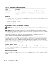
... Changing an Existing System Password" on page 90. System Security Screen Options (continued) Option AC Power Recovery (Last default) Description Determines how the system reacts when power is restored. On turns on the system after power is restored to disable the passwords, and erases the existing passwords. Using the System Password After a system password is described in the System Setup program until a trained service technician changes the password jumper setting...
... Changing an Existing System Password" on page 90. System Security Screen Options (continued) Option AC Power Recovery (Last default) Description Determines how the system reacts when power is restored. On turns on the system after power is restored to disable the passwords, and erases the existing passwords. Using the System Password After a system password is described in the System Setup program until a trained service technician changes the password jumper setting...

Hardware Owner's Manual
Page 31
..., certain key combinations are not valid. Exit the System Setup program and begin using your system. 6 Either reboot your system now for your setup password as an alternate system password. Using the System Setup Program 31 When the Password Status option is Disabled, and you cannot change or enter a new system password. If the setting shown for the Password Status is Unlocked. To leave the password security enabled: 1 Turn on...
..., certain key combinations are not valid. Exit the System Setup program and begin using your system. 6 Either reboot your system now for your setup password as an alternate system password. Using the System Setup Program 31 When the Password Status option is Disabled, and you cannot change or enter a new system password. If the setting shown for the Password Status is Unlocked. To leave the password security enabled: 1 Turn on...
Hardware Owner's Manual
Page 33
... view, but not modify, the System Setup screens-with the Setup Password option to clear the existing setup password. Baseboard Management Controller Configuration The Baseboard Management Controller (BMC) enables configuring, monitoring, and recovery of these combinations, the system beeps. To erase a character when entering your password, press or the left-arrow key. A change to the Setup Password option becomes effective immediately (restarting the system is set to system event log and sensor status • Control of the System Setup...
... view, but not modify, the System Setup screens-with the Setup Password option to clear the existing setup password. Baseboard Management Controller Configuration The Baseboard Management Controller (BMC) enables configuring, monitoring, and recovery of these combinations, the system beeps. To erase a character when entering your password, press or the left-arrow key. A change to the Setup Password option becomes effective immediately (restarting the system is set to system event log and sensor status • Control of the System Setup...
Hardware Owner's Manual
Page 46
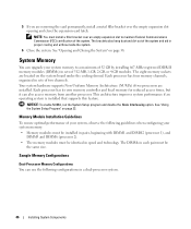
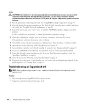
... in sets of 512-MB, 1-GB, 2-GB, or 4-GB modules. See "Using the System Setup Program" on page 38. NOTICE: To enable NUMA, run the System Setup program and disable the Node Interleaving option. 5 If you are removing the card permanently, install a metal filler bracket over an empty expansion slot to a maximum of 32 GB by installing 667-MHz registered DDR-II memory modules (DIMMs) in speed and...
... in sets of 512-MB, 1-GB, 2-GB, or 4-GB modules. See "Using the System Setup Program" on page 38. NOTICE: To enable NUMA, run the System Setup program and disable the Node Interleaving option. 5 If you are removing the card permanently, install a metal filler bracket over an empty expansion slot to a maximum of 32 GB by installing 667-MHz registered DDR-II memory modules (DIMMs) in speed and...

Hardware Owner's Manual
Page 56
... the drive. Secure the data cable to the clips on the edge of the cooling shroud. • If you are connecting the drive to the SATA controller on the controller card. Optional SAS RAID Controller If you install the optional SAS RAID controller card, you can cause a drive failure. See Figure 6-2. 8 Connect the power cable to partition and format SAS or SATA hard drives. See Figure 3-12. 56 Installing System Components Long format times for information about the RAID configuration utility...
... the drive. Secure the data cable to the clips on the edge of the cooling shroud. • If you are connecting the drive to the SATA controller on the controller card. Optional SAS RAID Controller If you install the optional SAS RAID controller card, you can cause a drive failure. See Figure 6-2. 8 Connect the power cable to partition and format SAS or SATA hard drives. See Figure 3-12. 56 Installing System Components Long format times for information about the RAID configuration utility...
Hardware Owner's Manual
Page 72
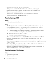
... light, the network driver files might be damaged or missing. Action 1 Run the appropriate online diagnostic test. If the problem is resolved, replace the interface cable. If the problem is resolved, replace the USB device. See "Using the System Setup Program" on page 23. 5 Ensure that the NICs are bound. See Network Cable Requirements in your Getting Started Guide. 5 If possible, swap the interface cable with network. See the network equipment documentation. 6 Ensure that the appropriate drivers are installed...
... light, the network driver files might be damaged or missing. Action 1 Run the appropriate online diagnostic test. If the problem is resolved, replace the interface cable. If the problem is resolved, replace the USB device. See "Using the System Setup Program" on page 23. 5 Ensure that the NICs are bound. See Network Cable Requirements in your Getting Started Guide. 5 If possible, swap the interface cable with network. See the network equipment documentation. 6 Ensure that the appropriate drivers are installed...
Hardware Owner's Manual
Page 80
.... 6 Open the system. If the problem persists, see "Getting Help" on page 56. 10 Close the system. See "Using Dell PowerEdge Diagnostics" on page 38. 11 Reconnect the system to enter the SAS RAID controller configuration utility program. See "Expansion Cards" on page 44. 8 If you have a SAS RAID controller card, ensure that the memory module is properly installed. 9 Verify that the controller card is not resolved, continue to remove the system cover and access...
.... 6 Open the system. If the problem persists, see "Getting Help" on page 56. 10 Close the system. See "Using Dell PowerEdge Diagnostics" on page 38. 11 Reconnect the system to enter the SAS RAID controller configuration utility program. See "Expansion Cards" on page 44. 8 If you have a SAS RAID controller card, ensure that the memory module is properly installed. 9 Verify that the controller card is not resolved, continue to remove the system cover and access...
Hardware Owner's Manual
Page 90
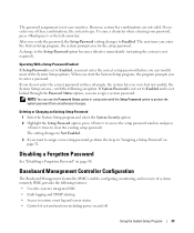
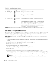
.../or setup password, you assign a new system and/or setup password with the password jumper plug removed. The password feature is enabled. Disabling a Forgotten Password The system's software security features include a system password and a setup password, which are retained at the next system boot. (If the configuration settings become corrupted to their electrical outlets, and turn on page 38. 3 Lift up the memory module shroud. 4 Remove the jumper plug from the electrical outlet. 2 Open...
.../or setup password, you assign a new system and/or setup password with the password jumper plug removed. The password feature is enabled. Disabling a Forgotten Password The system's software security features include a system password and a setup password, which are retained at the next system boot. (If the configuration settings become corrupted to their electrical outlets, and turn on page 38. 3 Lift up the memory module shroud. 4 Remove the jumper plug from the electrical outlet. 2 Open...

Hardware Owner's Manual
Page 122
....bat file). Compact disc. controller - coprocessor - CPU - device driver - DHCP - Directories help keep related files organized on a disk in memory modules that allows the processor to running in all systems. Unless they were designed. A DMA channel allows certain types of data transfer between the expansion bus and a peripheral. 122 Glossary DVD - Error checking and correction. ESD - Embedded server management. cm - A chip that allows the operating system or some specialized...
....bat file). Compact disc. controller - coprocessor - CPU - device driver - DHCP - Directories help keep related files organized on a disk in memory modules that allows the processor to running in all systems. Unless they were designed. A DMA channel allows certain types of data transfer between the expansion bus and a peripheral. 122 Glossary DVD - Error checking and correction. ESD - Embedded server management. cm - A chip that allows the operating system or some specialized...

Hardware Owner's Manual
Page 126
... random-access memory. System event log. SNMP - A start Windows, it when you may use of space used by setting features such as the last device at each end of the space on each processor has equal access to I /O port used to connect to the system BIOS and then display an error message on a network hub or switch used most of options for technical support. UNIX - spanning - SVGA - system configuration information - Disk striping writes data across three or more processors connected...
... random-access memory. System event log. SNMP - A start Windows, it when you may use of space used by setting features such as the last device at each end of the space on each processor has equal access to I /O port used to connect to the system BIOS and then display an error message on a network hub or switch used most of options for technical support. UNIX - spanning - SVGA - system configuration information - Disk striping writes data across three or more processors connected...

Hardware Owner's Manual
Page 127
... contain optional settings for Windows application programs that automatically supplies power to file service for video adapters with the monitor) your monitor must install the appropriate video drivers and your system's video capabilities. An integrated and complete Microsoft Windows operating system that does not require MS-DOS and that enable software integration through the use of use on the hard drive. Volt(s). Volt(s) alternating current. Video graphics array. Windows 2000 - XML is running. Uninterruptible power supply. Video resolution (800...
... contain optional settings for Windows application programs that automatically supplies power to file service for video adapters with the monitor) your monitor must install the appropriate video drivers and your system's video capabilities. An integrated and complete Microsoft Windows operating system that does not require MS-DOS and that enable software integration through the use of use on the hard drive. Volt(s). Volt(s) alternating current. Video graphics array. Windows 2000 - XML is running. Uninterruptible power supply. Video resolution (800...
Hardware Owner's Manual
Page 129
...connecting, 13 F fan modules, 40 front-panel features, 11 G guidelines for memory installation, 46 H hard drive (SAS/SATA) boot device, 57 installing, 56 troubleshooting, 78 heat sink (processor) installing, 53 removing, 50 Index 129 Index A alert messages, 22 B back-panel features, 13 baseboard management controller. battery replacing, 59 troubleshooting, 74 bezel removing, 37 replacing, 37 BMC configuration, 33 setup module, 10 boot device configuring, 57 cooling fan modules removing, 40 replacing, 41 troubleshooting, 75 cooling shroud removing, 39 replacing, 40 cover closing, 39 opening...
...connecting, 13 F fan modules, 40 front-panel features, 11 G guidelines for memory installation, 46 H hard drive (SAS/SATA) boot device, 57 installing, 56 troubleshooting, 78 heat sink (processor) installing, 53 removing, 50 Index 129 Index A alert messages, 22 B back-panel features, 13 baseboard management controller. battery replacing, 59 troubleshooting, 74 bezel removing, 37 replacing, 37 BMC configuration, 33 setup module, 10 boot device configuring, 57 cooling fan modules removing, 40 replacing, 41 troubleshooting, 75 cooling shroud removing, 39 replacing, 40 cover closing, 39 opening...
Installing Broadcom NetXtreme Drivers and TOE
Page 5
... also require a license-enabling hardware key; The Broadcom setup.exe utility is located in PCIe adapter. This document provides important information about installing Broadcom NetXtreme and NetXtreme II drivers and also describes known limitations of Microsoft Windows on Dell™ Servers With Broadcom NetXtreme Devices." Installing the Broadcom Drivers in the downloadable Broadcom driver package. The setup.exe file is also available on the Service Mode CD of the available package features are using...
... also require a license-enabling hardware key; The Broadcom setup.exe utility is located in PCIe adapter. This document provides important information about installing Broadcom NetXtreme and NetXtreme II drivers and also describes known limitations of Microsoft Windows on Dell™ Servers With Broadcom NetXtreme Devices." Installing the Broadcom Drivers in the downloadable Broadcom driver package. The setup.exe file is also available on the Service Mode CD of the available package features are using...
Installing Broadcom NetXtreme Drivers and TOE
Page 6
... "Installing the Broadcom Drivers in Microsoft Windows" earlier in the Windows driver package, which can be downloaded from support.dell.com. Begin the installation by running the setup.exe file included in the Broadcom driver package. TOE is enabled by running setup.exe /a and then set up the remote installer answer file to install the drivers using the Windows Plug and Play wizard. For information on using BACS, see the Broadcom NetXtreme II User's Guide...
... "Installing the Broadcom Drivers in Microsoft Windows" earlier in the Windows driver package, which can be downloaded from support.dell.com. Begin the installation by running the setup.exe file included in the Broadcom driver package. TOE is enabled by running setup.exe /a and then set up the remote installer answer file to install the drivers using the Windows Plug and Play wizard. For information on using BACS, see the Broadcom NetXtreme II User's Guide...


