
Glossary
Page 1
Alternating current. backup - A module that includes power supplies and fans. Baseboard management controller. bus - Certificate authority. cm - Ampere(s). ambient temperature - ANSI - asset tag - The modules are mounted into a chassis that contains ...interchange of CIM data with controllers for security or tracking purposes. Your system contains an expansion bus that keeps a copy of a system. Dell™ Glossary NOTE: For additional information on storage terminology, visit the Storage Networking Industry Association's website at www.snia.org and click ...
Alternating current. backup - A module that includes power supplies and fans. Baseboard management controller. bus - Certificate authority. cm - Ampere(s). ambient temperature - ANSI - asset tag - The modules are mounted into a chassis that contains ...interchange of CIM data with controllers for security or tracking purposes. Your system contains an expansion bus that keeps a copy of a system. Dell™ Glossary NOTE: For additional information on storage terminology, visit the Storage Networking Industry Association's website at www.snia.org and click ...

Glossary
Page 3
... protocol. g - G - A video mode that implements communication between the system board and storage devices. Hz - IDE - Integrated Dell Remote Access Controller. InfiniBand offers point-to insert or install a device, typically a hard drive or an internal cooling fan, into the host system while the system is the data path and physical interface between the...
... protocol. g - G - A video mode that implements communication between the system board and storage devices. Hz - IDE - Integrated Dell Remote Access Controller. InfiniBand offers point-to insert or install a device, typically a hard drive or an internal cooling fan, into the host system while the system is the data path and physical interface between the...

Hardware Owner's Manual
Page 6
... Controller Card 105 System Memory 106 General Memory Module Installation Guidelines 106 Mode-Specific Guidelines 106 Installing Memory Modules 109 Removing Memory Modules 111 Cooling Fans 112 Removing a Cooling Fan 112 6 Contents
... Controller Card 105 System Memory 106 General Memory Module Installation Guidelines 106 Mode-Specific Guidelines 106 Installing Memory Modules 109 Removing Memory Modules 111 Cooling Fans 112 Removing a Cooling Fan 112 6 Contents

Hardware Owner's Manual
Page 7
Installing a Cooling Fan 113 iDRAC6 Express Card (Optional 114 Installing an iDRAC6 Express Card 114 Removing an iDRAC6 Express Card 116 iDRAC6 Enterprise Card (Optional 117 Installing an ...
Installing a Cooling Fan 113 iDRAC6 Express Card (Optional 114 Installing an iDRAC6 Express Card 114 Removing an iDRAC6 Express Card 116 iDRAC6 Enterprise Card (Optional 117 Installing an ...

Hardware Owner's Manual
Page 9
Troubleshooting a Fan 152 Troubleshooting System Memory 153 Troubleshooting an Internal USB Key 155 Troubleshooting an Optical Drive 156 Troubleshooting a Tape Backup Unit 157 Troubleshooting a Hard Drive 158 ...
Troubleshooting a Fan 152 Troubleshooting System Memory 153 Troubleshooting an Internal USB Key 155 Troubleshooting an Optical Drive 156 Troubleshooting a Tape Backup Unit 157 Troubleshooting a Hard Drive 158 ...

Hardware Owner's Manual
Page 27
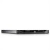
...to the system for 10 seconds and restart the system. See "Troubleshooting System Cooling Problems" on page 169. Table 1-2. CPU Power Fault. Fan module ## RPM exceeding range. Corrective Actions Reseat the processor. If the problem persists, see "Getting Help" on page 151. Check LCD for... the system. About Your System 27 Memory Regulator # One of over-heating. One of intended operating range. Check fan. Fan redundancy The system is outside of specified fan in specified module is no longer lost. If the problem persists, see "Getting Help" on page 169. See ...
...to the system for 10 seconds and restart the system. See "Troubleshooting System Cooling Problems" on page 169. Table 1-2. CPU Power Fault. Fan module ## RPM exceeding range. Corrective Actions Reseat the processor. If the problem persists, see "Getting Help" on page 151. Check LCD for... the system. About Your System 27 Memory Regulator # One of over-heating. One of intended operating range. Check fan. Fan redundancy The system is outside of specified fan in specified module is no longer lost. If the problem persists, see "Getting Help" on page 169. See ...
Hardware Owner's Manual
Page 37
... the system. can often specify a very precise fault condition that the problem is not installed in this table, see the Glossary at support.dell.com/manuals. NOTE: For the full name of range, the LCD displays the fault; LCD Status Messages (Optional) (continued) Code Text... power supply. Table 1-2. Check PSU and config. Removing LCD Status Messages (Optional) For faults associated with sensors, such as temperature, voltage, fans, and so on the LCD can boot if throttled. The system configuration requires more power Check PSU and than what the power system supply can...
... the system. can often specify a very precise fault condition that the problem is not installed in this table, see the Glossary at support.dell.com/manuals. NOTE: For the full name of range, the LCD displays the fault; LCD Status Messages (Optional) (continued) Code Text... power supply. Table 1-2. Check PSU and config. Removing LCD Status Messages (Optional) For faults associated with sensors, such as temperature, voltage, fans, and so on the LCD can boot if throttled. The system configuration requires more power Check PSU and than what the power system supply can...
Hardware Owner's Manual
Page 52
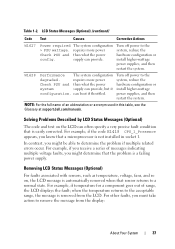
... to a possible problem and prompts you run diagnostic tests on your system. Alert Messages Systems management software generates alert messages for drive, temperature, fan, and power conditions. See "Running the Embedded System Diagnostics" on the diskette. Diagnostics Messages The system diagnostic utilities may lose all data on ...page 162 for more information, see the systems management software documentation at support.dell.com/manuals. 52 About Your System NOTE: Warning messages are generated by typing y (yes) or n (no).
... to a possible problem and prompts you run diagnostic tests on your system. Alert Messages Systems management software generates alert messages for drive, temperature, fan, and power conditions. See "Running the Embedded System Diagnostics" on the diskette. Diagnostics Messages The system diagnostic utilities may lose all data on ...page 162 for more information, see the systems management software documentation at support.dell.com/manuals. 52 About Your System NOTE: Warning messages are generated by typing y (yes) or n (no).

Hardware Owner's Manual
Page 56
..." on page 63, "Using the System Password" on page 68, and "Using the Setup Password" on page 62. Displays a screen to each of the processor, fans, and memory modules with the NumLock mode activated on page 57. See "Power Management Screen" on page 70. Displays a screen to enable or disable the...
..." on page 63, "Using the System Password" on page 68, and "Using the Setup Password" on page 62. Displays a screen to each of the processor, fans, and memory modules with the NumLock mode activated on page 57. See "Power Management Screen" on page 70. Displays a screen to enable or disable the...

Hardware Owner's Manual
Page 62
In this screen as follows: • OS Control sets the CPU power to OS DBPM, the fan power to Minimum Power, and the memory power to Maximum Performance. Memory Power and Performance Management Options are OS DBPM, System DBPM, ... the power settings on processor utilization. • Maximum Performance sets all processor performance information is passed from the system BIOS to Maximum Performance. Fan Power and Performance Management Options are OS Control, Active Power Controller, Custom, or Maximum Performance. The operating system sets the processor performance based ...
In this screen as follows: • OS Control sets the CPU power to OS DBPM, the fan power to Minimum Power, and the memory power to Maximum Performance. Memory Power and Performance Management Options are OS DBPM, System DBPM, ... the power settings on processor utilization. • Maximum Performance sets all processor performance information is passed from the system BIOS to Maximum Performance. Fan Power and Performance Management Options are OS Control, Active Power Controller, Custom, or Maximum Performance. The operating system sets the processor performance based ...
Hardware Owner's Manual
Page 76
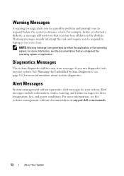
Figure 3-1. Inside the System 11 10 1 2 3 9 8 7 1 cooling shroud 3 expansion-card risers (2) 5 memory modules (6) 7 control panel board 9 hard drives (4) 11 power supply shroud 4 5 6 2 power supply bays (2) 4 heat sink/processor 6 optical drive 8 display module 10 system cooling fans (5) 76 Installing System Components
Figure 3-1. Inside the System 11 10 1 2 3 9 8 7 1 cooling shroud 3 expansion-card risers (2) 5 memory modules (6) 7 control panel board 9 hard drives (4) 11 power supply shroud 4 5 6 2 power supply bays (2) 4 heat sink/processor 6 optical drive 8 display module 10 system cooling fans (5) 76 Installing System Components

Hardware Owner's Manual
Page 101
... board. Damage due to cool before you touch it. The system may only be done by your product documentation, or as directed by the cooling fan modules, which are positioned directly beneath the cooling shroud. Installing System Components 101 Ensure that the memory modules and heat sink have had sufficient time... the processor, heat sink, and memory modules, and provides air flow to these components. Read and follow the safety instructions that is not authorized by Dell is facilitated by the online or telephone service and support team.
... board. Damage due to cool before you touch it. The system may only be done by your product documentation, or as directed by the cooling fan modules, which are positioned directly beneath the cooling shroud. Installing System Components 101 Ensure that the memory modules and heat sink have had sufficient time... the processor, heat sink, and memory modules, and provides air flow to these components. Read and follow the safety instructions that is not authorized by Dell is facilitated by the online or telephone service and support team.

Hardware Owner's Manual
Page 102
See "Opening and Closing the System" on the system board. 3 Push the cooling shroud down until all edges are secured to the system board. 4 Close the system. Figure 3-13. Installing and Removing the Cooling Shroud 1 2 4 3 1 power distribution board shroud 2 3 tabs (2) 4 system board shroud fan bay numbers Installing the Cooling Shroud 1 Orient the cooling shroud with the numbered fan bays as a guide. 2 Align the cooling shroud posts with the slots on page 78. 102 Installing System Components
See "Opening and Closing the System" on the system board. 3 Push the cooling shroud down until all edges are secured to the system board. 4 Close the system. Figure 3-13. Installing and Removing the Cooling Shroud 1 2 4 3 1 power distribution board shroud 2 3 tabs (2) 4 system board shroud fan bay numbers Installing the Cooling Shroud 1 Orient the cooling shroud with the numbered fan bays as a guide. 2 Align the cooling shroud posts with the slots on page 78. 102 Installing System Components

Hardware Owner's Manual
Page 112
.... Damage due to their power sources, and turn them on page 101. 4 Disconnect the fan's power cable from the system. Read and follow the safety instructions that is not authorized by Dell is the same. 1 Turn off the system, including any attached peripherals, and disconnect the ...system from the fan assembly. NOTE: The procedure for the fan to easily identify and replace the proper fan by your product documentation, or as applicable. ...
.... Damage due to their power sources, and turn them on page 101. 4 Disconnect the fan's power cable from the system. Read and follow the safety instructions that is not authorized by Dell is the same. 1 Turn off the system, including any attached peripherals, and disconnect the ...system from the fan assembly. NOTE: The procedure for the fan to easily identify and replace the proper fan by your product documentation, or as applicable. ...

Hardware Owner's Manual
Page 113
Installing System Components 113 See Figure 3-16. 3 Connect the fan's power cable to the power connector on page 102. Removing and Installing a Fan 1 2 1 fan 2 power cable Installing a Cooling Fan 1 Ensure that the side with the power cable faces toward the back of the system. 2 Lower the fan into the fan assembly until the fan is oriented correctly. See "Installing the Cooling Shroud" on the system board. 4 Replace the cooling shroud or power distribution board shroud as applicable. Orient the fan module so that the fan is fully seated. Figure 3-16.
Installing System Components 113 See Figure 3-16. 3 Connect the fan's power cable to the power connector on page 102. Removing and Installing a Fan 1 2 1 fan 2 power cable Installing a Cooling Fan 1 Ensure that the side with the power cable faces toward the back of the system. 2 Lower the fan into the fan assembly until the fan is oriented correctly. See "Installing the Cooling Shroud" on the system board. 4 Replace the cooling shroud or power distribution board shroud as applicable. Orient the fan module so that the fan is fully seated. Figure 3-16.
Hardware Owner's Manual
Page 138
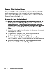
...then lift the board out. You should only perform troubleshooting and simple repairs as authorized in your system directly behind the power supply fan modules. Power Distribution Board The power distribution board is not covered by your warranty. See Figure 3-26. 138 Installing System Components ...Read and follow the safety instructions that is not authorized by Dell is located in your product documentation, or as directed by the online or telephone service and support team. Removing the Power Distribution ...
...then lift the board out. You should only perform troubleshooting and simple repairs as authorized in your system directly behind the power supply fan modules. Power Distribution Board The power distribution board is not covered by your warranty. See Figure 3-26. 138 Installing System Components ...Read and follow the safety instructions that is not authorized by Dell is located in your product documentation, or as directed by the online or telephone service and support team. Removing the Power Distribution ...

Hardware Owner's Manual
Page 139
Figure 3-26. Power Distribution Board 6 5 1 2 4 3 1 screws (2) 3 power-distribution board 5 fan module cable connectors (2) 2 power supply cables (2) 4 standoffs (2) 6 fan module power cables (2) Installing System Components 139
Figure 3-26. Power Distribution Board 6 5 1 2 4 3 1 screws (2) 3 power-distribution board 5 fan module cable connectors (2) 2 power supply cables (2) 4 standoffs (2) 6 fan module power cables (2) Installing System Components 139

Hardware Owner's Manual
Page 140
See Figure 3-26. 3 Install the two screws that is not authorized by Dell is not covered by your product documentation, or as directed by a certified service technician. See "Installing the Cooling Shroud" on page 102. 6 Orient the power ... in your warranty. You should only perform troubleshooting and simple repairs as authorized in Figure 3-26. 5 Locate the hinged interior catches on page 141) and fan cable connectors to the system board (see "System Board" on either side of the shroud and align and seat the power distribution board shroud, rotating...
See Figure 3-26. 3 Install the two screws that is not authorized by Dell is not covered by your product documentation, or as directed by a certified service technician. See "Installing the Cooling Shroud" on page 102. 6 Orient the power ... in your warranty. You should only perform troubleshooting and simple repairs as authorized in Figure 3-26. 5 Locate the hinged interior catches on page 141) and fan cable connectors to the system board (see "System Board" on either side of the shroud and align and seat the power distribution board shroud, rotating...
Hardware Owner's Manual
Page 149
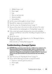
... or telephone service and support team. Damage due to the electrical outlet and turn on page 78. 2 Ensure that is not authorized by Dell is not covered by your product documentation, or as directed by a certified service technician. See "Opening the System" on the system. •...; iDRAC6 Express card • Power supply • Fans • Processor and heat sink • Memory modules • System Battery 4 Let the system dry thoroughly for at least 24 hours. 5 Reinstall the...
... or telephone service and support team. Damage due to the electrical outlet and turn on page 78. 2 Ensure that is not authorized by Dell is not covered by your product documentation, or as directed by a certified service technician. See "Opening the System" on the system. •...; iDRAC6 Express card • Power supply • Fans • Processor and heat sink • Memory modules • System Battery 4 Let the system dry thoroughly for at least 24 hours. 5 Reinstall the...
Hardware Owner's Manual
Page 151
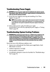
... Supplies" on page 152. Read and follow the safety instructions that is not authorized by Dell is not covered by replacing the power supply, see "Getting Help" on page 169. See "Troubleshooting a Fan" on page 125. Troubleshooting Power Supply CAUTION: At least one power supply installed for extended...or back filler bracket is removed. • Ambient temperature is too high. • External airflow is obstructed. • An individual cooling fan is removed or has failed. The power indicator turns green to signify that none of time can cause the system to servicing that came with...
... Supplies" on page 152. Read and follow the safety instructions that is not authorized by Dell is not covered by replacing the power supply, see "Getting Help" on page 169. See "Troubleshooting a Fan" on page 125. Troubleshooting Power Supply CAUTION: At least one power supply installed for extended...or back filler bracket is removed. • Ambient temperature is too high. • External airflow is obstructed. • An individual cooling fan is removed or has failed. The power indicator turns green to signify that none of time can cause the system to servicing that came with...


