
Hardware Owner's Manual
Page 8
SAS Backplane 135 Removing the SAS Backplane 135 Installing the SAS Backplane 137 Power Distribution Board 138 Removing the Power Distribution Board 138 Replacing the Power Distribution Board 140 System Board 141 Removing the System Board 141 Installing the System Board 143 4 Troubleshooting Your System 145 Safety First-For You and Your System ...Device 147 Troubleshooting a NIC 147 Troubleshooting a Wet System 148 Troubleshooting a Damaged System 149 Troubleshooting the System Battery 150 Troubleshooting Power Supply 151 Troubleshooting System Cooling Problems 151 8 Contents
SAS Backplane 135 Removing the SAS Backplane 135 Installing the SAS Backplane 137 Power Distribution Board 138 Removing the Power Distribution Board 138 Replacing the Power Distribution Board 140 System Board 141 Removing the System Board 141 Installing the System Board 143 4 Troubleshooting Your System 145 Safety First-For You and Your System ...Device 147 Troubleshooting a NIC 147 Troubleshooting a Wet System 148 Troubleshooting a Damaged System 149 Troubleshooting the System Battery 150 Troubleshooting Power Supply 151 Troubleshooting System Cooling Problems 151 8 Contents

Hardware Owner's Manual
Page 101
... by Dell is facilitated by a certified service technician. Read and follow the safety instructions that came with the cooling shroud removed. See Figure 3-13. Cooling Shroud The system board shroud covers the processor, heat sink, and memory modules, and provides air flow to cool before you touch it. The power distribution board shroud covers the power distribution board...
... by Dell is facilitated by a certified service technician. Read and follow the safety instructions that came with the cooling shroud removed. See Figure 3-13. Cooling Shroud The system board shroud covers the processor, heat sink, and memory modules, and provides air flow to cool before you touch it. The power distribution board shroud covers the power distribution board...

Hardware Owner's Manual
Page 102
See "Opening and Closing the System" on the system board. 3 Push the cooling shroud down until all edges are secured to the system board. 4 Close the system. Figure 3-13. Installing and Removing the Cooling Shroud 1 2 4 3 1 power distribution board shroud 2 3 tabs (2) 4 system board shroud fan bay numbers Installing the Cooling Shroud 1 Orient the cooling shroud with the numbered fan bays as a guide. 2 Align the cooling shroud posts with the slots on page 78. 102 Installing System Components
See "Opening and Closing the System" on the system board. 3 Push the cooling shroud down until all edges are secured to the system board. 4 Close the system. Figure 3-13. Installing and Removing the Cooling Shroud 1 2 4 3 1 power distribution board shroud 2 3 tabs (2) 4 system board shroud fan bay numbers Installing the Cooling Shroud 1 Orient the cooling shroud with the numbered fan bays as a guide. 2 Align the cooling shroud posts with the slots on page 78. 102 Installing System Components

Hardware Owner's Manual
Page 112
... fan module is not covered by a certified service technician. See "Cooling Shroud" on page 78. 3 Remove the cooling shroud or power distribution board shroud as directed by noting the fan numbers on . CAUTION: Many repairs may only be done by your product documentation, or as applicable.... Read and follow the safety instructions that is not authorized by Dell is the same. 1 Turn off the system, including any attached peripherals, and disconnect the system from the system. 7 Close the system. ...
... fan module is not covered by a certified service technician. See "Cooling Shroud" on page 78. 3 Remove the cooling shroud or power distribution board shroud as directed by noting the fan numbers on . CAUTION: Many repairs may only be done by your product documentation, or as applicable.... Read and follow the safety instructions that is not authorized by Dell is the same. 1 Turn off the system, including any attached peripherals, and disconnect the system from the system. 7 Close the system. ...

Hardware Owner's Manual
Page 113
Orient the fan module so that the fan is fully seated. Figure 3-16. Installing System Components 113 Removing and Installing a Fan 1 2 1 fan 2 power cable Installing a Cooling Fan 1 Ensure that the side with the power cable faces toward the back of the system. 2 Lower the fan into the fan assembly until the fan is oriented correctly. See "Installing the Cooling Shroud" on the system board. 4 Replace the cooling shroud or power distribution board shroud as applicable. See Figure 3-16. 3 Connect the fan's power cable to the power connector on page 102.
Orient the fan module so that the fan is fully seated. Figure 3-16. Installing System Components 113 Removing and Installing a Fan 1 2 1 fan 2 power cable Installing a Cooling Fan 1 Ensure that the side with the power cable faces toward the back of the system. 2 Lower the fan into the fan assembly until the fan is oriented correctly. See "Installing the Cooling Shroud" on the system board. 4 Replace the cooling shroud or power distribution board shroud as applicable. See Figure 3-16. 3 Connect the fan's power cable to the power connector on page 102.

Hardware Owner's Manual
Page 126
Figure 3-21. 2 Disconnect the power cable from the power distribution board and clear the chassis. NOTE: You may have to release it interferes with power-supply removal. For information about the cable management arm, see the system's rack documentation. 3 Press the release latch and pull the power supply straight out to unlatch and lift the optional cable...
Figure 3-21. 2 Disconnect the power cable from the power distribution board and clear the chassis. NOTE: You may have to release it interferes with power-supply removal. For information about the cable management arm, see the system's rack documentation. 3 Press the release latch and pull the power supply straight out to unlatch and lift the optional cable...
Hardware Owner's Manual
Page 138
... Dell is located in your product documentation, or as authorized in your warranty. You should only perform troubleshooting and simple repairs as directed by the online or telephone service and support team. Damage due to the power supplies through the power distribution shroud that came with the product. 1 Remove the power supplies from the system board...
... Dell is located in your product documentation, or as authorized in your warranty. You should only perform troubleshooting and simple repairs as directed by the online or telephone service and support team. Damage due to the power supplies through the power distribution shroud that came with the product. 1 Remove the power supplies from the system board...

Hardware Owner's Manual
Page 139
Figure 3-26. Power Distribution Board 6 5 1 2 4 3 1 screws (2) 3 power-distribution board 5 fan module cable connectors (2) 2 power supply cables (2) 4 standoffs (2) 6 fan module power cables (2) Installing System Components 139
Figure 3-26. Power Distribution Board 6 5 1 2 4 3 1 screws (2) 3 power-distribution board 5 fan module cable connectors (2) 2 power supply cables (2) 4 standoffs (2) 6 fan module power cables (2) Installing System Components 139

Hardware Owner's Manual
Page 140
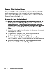
... to servicing that is not authorized by Dell is not covered by your product documentation, or as directed by a certified service technician. See Figure 3-26. 4 Connect the power distribution cables to the system board (see "System Board" on page 141) and fan cable ...the two screws that came with the product. 1 Unpack the new power distribution board assembly. 2 Align the power distribution board with the fan markings on the chassis. Read and follow the safety instructions that secure the power distribution board to the fan modules and replace the shroud. See "Installing the...
... to servicing that is not authorized by Dell is not covered by your product documentation, or as directed by a certified service technician. See Figure 3-26. 4 Connect the power distribution cables to the system board (see "System Board" on page 141) and fan cable ...the two screws that came with the product. 1 Unpack the new power distribution board assembly. 2 Align the power distribution board with the fan markings on the chassis. Read and follow the safety instructions that secure the power distribution board to the fan modules and replace the shroud. See "Installing the...


