Rack Installation Guide
Page 8
... where loss of a rack; The procedures for trained service technicians installing one or more systems in most industry-standard rack cabinets. the slide rails can be extremely heavy and move easily on page 18. 6 Four-Post Rack Installation One rack kit is required for support and to prevent the cabinet from the rack. • Use caution when pressing the component rail release latches and sliding...
... where loss of a rack; The procedures for trained service technicians installing one or more systems in most industry-standard rack cabinets. the slide rails can be extremely heavy and move easily on page 18. 6 Four-Post Rack Installation One rack kit is required for support and to prevent the cabinet from the rack. • Use caution when pressing the component rail release latches and sliding...
Rack Installation Guide
Page 30
... up , and load the heaviest item in the rack first. • Make sure that provides power to the rack. Recommended Tools and Supplies • #2 Phillips screwdriver • 3/8-inch wrench or nut driver (if changing bracket to flush-mount configuration) • Masking tape or felt-tip pen to others . Using the rack kit for another system may be very large and heavy...
... up , and load the heaviest item in the rack first. • Make sure that provides power to the rack. Recommended Tools and Supplies • #2 Phillips screwdriver • 3/8-inch wrench or nut driver (if changing bracket to flush-mount configuration) • Masking tape or felt-tip pen to others . Using the rack kit for another system may be very large and heavy...

Getting Started Guide
Page 6
... remote access controller for remote systems management, which is installed on the dedicated slot on the optional bezel. • An integrated Trusted Platform Module (TPM) version 1.2 used for the two redundant PSUs (hot-plug hard drives and redundant PSU configuration). • Serial connector for console redirection support. • Security features, including chassis-intrusion detection and keylock on the system board. • Optional USB flash drive emulates a diskette drive or hard drive. • One 400-W power supply (optional redundant power supply available...
... remote access controller for remote systems management, which is installed on the dedicated slot on the optional bezel. • An integrated Trusted Platform Module (TPM) version 1.2 used for the two redundant PSUs (hot-plug hard drives and redundant PSU configuration). • Serial connector for console redirection support. • Security features, including chassis-intrusion detection and keylock on the system board. • Optional USB flash drive emulates a diskette drive or hard drive. • One 400-W power supply (optional redundant power supply available...

Hardware Owner's Manual (PDF)
Page 35
... more memory is disabled: than one DIMM is request has been detected complete. Replace the diskette. See "Troubleshooting a Diskette Drive" on page 135. Decreasing available memory Faulty or improperly installed memory modules. Faulty diskette, faulty or improperly connected diskette/tape drive interface cable, or loose power cable. Remote Configuration Wait until the process is present, DIMMs must be installed in the System Setup program, or loose diskette/tape drive interface cable, or loose power cable. BIOS Update Attempt Remote BIOS update Failed! See...
... more memory is disabled: than one DIMM is request has been detected complete. Replace the diskette. See "Troubleshooting a Diskette Drive" on page 135. Decreasing available memory Faulty or improperly installed memory modules. Faulty diskette, faulty or improperly connected diskette/tape drive interface cable, or loose power cable. Remote Configuration Wait until the process is present, DIMMs must be installed in the System Setup program, or loose diskette/tape drive interface cable, or loose power cable. BIOS Update Attempt Remote BIOS update Failed! See...

Hardware Owner's Manual (PDF)
Page 38
... drive. USB Key" on page 137 and "Troubleshooting a Hard Drive" on setting the order of boot devices. No timer tick interrupt Faulty system board. PCI BIOS failed to expansion card(s) loose; If Cables to install PCIe device BIOS Reseat the expansion card(s). (Option ROM) checksum Ensure that all appropriate failure detected during cables are securely connected shadowing. No boot sector on page 147. to the expansion card(s). If the problem drive, or hard-drive persists, see "Troubleshooting Expansion Cards" on hard drive Incorrect configuration settings...
... drive. USB Key" on page 137 and "Troubleshooting a Hard Drive" on setting the order of boot devices. No timer tick interrupt Faulty system board. PCI BIOS failed to expansion card(s) loose; If Cables to install PCIe device BIOS Reseat the expansion card(s). (Option ROM) checksum Ensure that all appropriate failure detected during cables are securely connected shadowing. No boot sector on page 147. to the expansion card(s). If the problem drive, or hard-drive persists, see "Troubleshooting Expansion Cards" on hard drive Incorrect configuration settings...

Hardware Owner's Manual (PDF)
Page 51
... model number, drive type, and size of the device attached to boot from the network. Integrated Devices Screen Table 2-6 lists the options and descriptions for the information fields that appear on the SATA Configuration screen. NOTE: When a SAS Card is plugged out, the SATA Configuration screen settings will be loaded to Port A. Integrated Devices Screen Options Option Internal USB Port (On default) Embedded Gb NICx (NIC1 default: Enabled with iSCSI Boot, and Disabled. The SATA controller field displays ATA Mode...
... model number, drive type, and size of the device attached to boot from the network. Integrated Devices Screen Table 2-6 lists the options and descriptions for the information fields that appear on the SATA Configuration screen. NOTE: When a SAS Card is plugged out, the SATA Configuration screen settings will be loaded to Port A. Integrated Devices Screen Options Option Internal USB Port (On default) Embedded Gb NICx (NIC1 default: Enabled with iSCSI Boot, and Disabled. The SATA controller field displays ATA Mode...

Hardware Owner's Manual (PDF)
Page 56
... the System Setup program until a trained service technician changes the password jumper setting to Setup System and Setup Password Features NOTICE: The password features provide a basic level of protection, such as data encryption programs. NOTICE: Anyone can access the data stored on page 59). To change settings in "Disabling a Forgotten Password" on your system unlocked so that someone can disable the password by changing a jumper setting. This procedure is a concern, operate your system...
... the System Setup program until a trained service technician changes the password jumper setting to Setup System and Setup Password Features NOTICE: The password features provide a basic level of protection, such as data encryption programs. NOTICE: Anyone can access the data stored on page 59). To change settings in "Disabling a Forgotten Password" on your system unlocked so that someone can disable the password by changing a jumper setting. This procedure is a concern, operate your system...

Hardware Owner's Manual (PDF)
Page 57
...-arrow key. However, certain key combinations are not valid. Using the System Password After a system password is Enabled. When a system password is assigned, the setting shown for the Password Status is in the field. If the Password Status option is Disabled, and you cannot change the system password. Using the System Setup Program 57 You can change the system password. If you assign a system password, enter the System Setup program and check...
...-arrow key. However, certain key combinations are not valid. Using the System Password After a system password is Enabled. When a system password is assigned, the setting shown for the Password Status is in the field. If the Password Status option is Disabled, and you cannot change the system password. Using the System Setup Program 57 You can change the system password. If you assign a system password, enter the System Setup program and check...

Hardware Owner's Manual (PDF)
Page 66
.... Using a riser card, the system can accommodate two expansion cards. 3 system board shroud 4 5 left riser 6 7 SAS RAID external controller 8 daughter card battery and memory module 9 SAS internal RAID controller 10 daughter card 11 RAC card 12 13 CPU/heatsink 14 15 SAS/SATA backplane cable 16 connector 17 hot plug hard drive bays 0 and 1 18 19 LCD control panel 20 21 control panel assembly 22 23 power distribution board 24 redundant power supplies (optional) SAS external controller daughter card center riser SAS card connector memory modules (6) dual fan module...
.... Using a riser card, the system can accommodate two expansion cards. 3 system board shroud 4 5 left riser 6 7 SAS RAID external controller 8 daughter card battery and memory module 9 SAS internal RAID controller 10 daughter card 11 RAC card 12 13 CPU/heatsink 14 15 SAS/SATA backplane cable 16 connector 17 hot plug hard drive bays 0 and 1 18 19 LCD control panel 20 21 control panel assembly 22 23 power distribution board 24 redundant power supplies (optional) SAS external controller daughter card center riser SAS card connector memory modules (6) dual fan module...

Hardware Owner's Manual (PDF)
Page 73
... use with the SAS/SATA backplane board. NOTICE: Do not turn off or reboot your system while the drive is configured correctly to support hot-plug drive removal and insertion. 3 Connect the SAS cable to the connector on the expansion card and route the cable through the SAS/SATA backplane board. See "Opening and Closing the System" on page 100 and Figure 6-4. NOTICE: Before attempting to remove or install a drive while the system is running, see the documentation for the SAS controller...
... use with the SAS/SATA backplane board. NOTICE: Do not turn off or reboot your system while the drive is configured correctly to support hot-plug drive removal and insertion. 3 Connect the SAS cable to the connector on the expansion card and route the cable through the SAS/SATA backplane board. See "Opening and Closing the System" on page 100 and Figure 6-4. NOTICE: Before attempting to remove or install a drive while the system is running, see the documentation for the SAS controller...

Hardware Owner's Manual (PDF)
Page 90
... use the internal USB connector, the Internal USB Port option must configure the USB memory key with your Product Information Guide for the system to the power plug at the back of the cable into a power distribution unit (PDU) or power outlet. The power supply status indicator will turn green to the power supply. Internal USB Memory Key The system provides an internal USB connector located on page 46. Loop the power cable and use with a USB flash memory key. See "System Setup Options" on the front control board for...
... use the internal USB connector, the Internal USB Port option must configure the USB memory key with your Product Information Guide for the system to the power plug at the back of the cable into a power distribution unit (PDU) or power outlet. The power supply status indicator will turn green to the power supply. Internal USB Memory Key The system provides an internal USB connector located on page 46. Loop the power cable and use with a USB flash memory key. See "System Setup Options" on the front control board for...
Hardware Owner's Manual (PDF)
Page 95
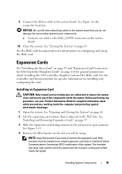
... SAS controller daughter card and the RAC card. Installing an Expansion Card CAUTION: Only trained service technicians are authorized to remove the system cover and access any procedure, see your Product Information Guide for specific information on page 97. 3 Slide the expansion-card sliding retainer to the retracted or open position. NOTE: Keep this bracket if you do not damage the surrounding system board components. 9 Connect the ribbon cable...
... SAS controller daughter card and the RAC card. Installing an Expansion Card CAUTION: Only trained service technicians are authorized to remove the system cover and access any procedure, see your Product Information Guide for specific information on page 97. 3 Slide the expansion-card sliding retainer to the retracted or open position. NOTE: Keep this bracket if you do not damage the surrounding system board components. 9 Connect the ribbon cable...

Hardware Owner's Manual (PDF)
Page 130
... "Entering the System Setup Program" on page 45. 5 Ensure that all network cables are all expansion cards installed in the system. See "Removing an Expansion Card" on the network are of an integrated NIC, see "Getting Help" on the switch or hub. • Change the autonegotiation setting, if possible. • Use another connector on page 165. If the problem persists, see the documentation for the NIC card. 3 Ensure that the...
... "Entering the System Setup Program" on page 45. 5 Ensure that all network cables are all expansion cards installed in the system. See "Removing an Expansion Card" on the network are of an integrated NIC, see "Getting Help" on the switch or hub. • Change the autonegotiation setting, if possible. • Use another connector on page 165. If the problem persists, see the documentation for the NIC card. 3 Ensure that the...
Hardware Owner's Manual (PDF)
Page 134
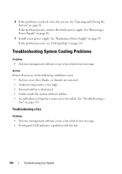
... cover, drive blanks, or shrouds are removed. • Ambient temperature is too high. • External airflow is obstructed. • Cables inside the system obstruct airflow. • An individual cooling fan is resolved, close the system. See "Replacing a Power Supply" on page 68. See "Opening and Closing the System" on page 89. Troubleshooting a Fan Problem • Systems management software issues a fan-related error message. • Front panel LCD indicates a problem with...
... cover, drive blanks, or shrouds are removed. • Ambient temperature is too high. • External airflow is obstructed. • Cables inside the system obstruct airflow. • An individual cooling fan is resolved, close the system. See "Replacing a Power Supply" on page 68. See "Opening and Closing the System" on page 89. Troubleshooting a Fan Problem • Systems management software issues a fan-related error message. • Front panel LCD indicates a problem with...

Hardware Owner's Manual (PDF)
Page 137
... be good. Troubleshooting an Internal USB Key Problem • System cannot read data from its electrical outlet, and turn on the system and attached peripherals. 11 Enter the System Setup program and check the system memory setting. 8 Reseat the memory modules in the first DIMM socket with a module of the same type and capacity that appears and the diagnostic indicators on the front of memory installed still does not...
... be good. Troubleshooting an Internal USB Key Problem • System cannot read data from its electrical outlet, and turn on the system and attached peripherals. 11 Enter the System Setup program and check the system memory setting. 8 Reseat the memory modules in the first DIMM socket with a module of the same type and capacity that appears and the diagnostic indicators on the front of memory installed still does not...
Hardware Owner's Manual (PDF)
Page 143
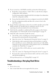
... SAS controller card or SAS RAID controller are installed and are securely seated in the System Setup program. b Open the system. d Verify that the hard drive has been configured correctly for information about the configuration utility. Troubleshooting a Hot-plug Hard Drive Problem • Device driver error. • One or more information. 5 Verify that the cable connections between the hard drive(s) and the drive controller are correct, whether the connections are to the electrical outlet, and turn on the system board, a SAS expansion card, or a SAS RAID controller...
... SAS controller card or SAS RAID controller are installed and are securely seated in the System Setup program. b Open the system. d Verify that the hard drive has been configured correctly for information about the configuration utility. Troubleshooting a Hot-plug Hard Drive Problem • Device driver error. • One or more information. 5 Verify that the cable connections between the hard drive(s) and the drive controller are correct, whether the connections are to the electrical outlet, and turn on the system board, a SAS expansion card, or a SAS RAID controller...

Hardware Owner's Manual (PDF)
Page 147
... inside the system. If the problem persists, go to remove the system cover and access any recommended actions provided by the diagnostics. Problem • Error message indicates a problem with an expansion card. • Expansion card performs incorrectly or not at all. Before performing any procedure, see "Getting Help" on page 68. 4 Ensure that the cable connections between the SAS/SATA backplane and the SAS controller are authorized to the next...
... inside the system. If the problem persists, go to remove the system cover and access any recommended actions provided by the diagnostics. Problem • Error message indicates a problem with an expansion card. • Expansion card performs incorrectly or not at all. Before performing any procedure, see "Getting Help" on page 68. 4 Ensure that the cable connections between the SAS/SATA backplane and the SAS controller are authorized to the next...

Hardware Owner's Manual (PDF)
Page 151
...; Display, print, or save test results. • Temporarily suspend testing if an error is detected or terminate testing when a user-defined error limit is a suite of menus and options for systems running supported Microsoft® Windows® and Linux operating systems are unable to fix the problem yourself, service and support personnel can use diagnostics test results to run the diagnostics before calling for technical assistance. For information about using the PowerEdge Diagnostics, then use the online Dell...
...; Display, print, or save test results. • Temporarily suspend testing if an error is detected or terminate testing when a user-defined error limit is a suite of menus and options for systems running supported Microsoft® Windows® and Linux operating systems are unable to fix the problem yourself, service and support personnel can use diagnostics test results to run the diagnostics before calling for technical assistance. For information about using the PowerEdge Diagnostics, then use the online Dell...
Hardware Owner's Manual (PDF)
Page 177
... you must install the appropriate video drivers and your monitor must support the resolution. An integrated and complete Microsoft Windows operating system that does not require MS-DOS and that enable software integration through the use of XML Web services. XML Web services are installed on the hard drive. Video graphics array. A start Windows, it consults the win.ini file to display at a specific graphics resolution, you start -up and down. Windows Powered - VDC - VGA...
... you must install the appropriate video drivers and your monitor must support the resolution. An integrated and complete Microsoft Windows operating system that does not require MS-DOS and that enable software integration through the use of XML Web services. XML Web services are installed on the hard drive. Video graphics array. A start Windows, it consults the win.ini file to display at a specific graphics resolution, you start -up and down. Windows Powered - VDC - VGA...
Hardware Owner's Manual (PDF)
Page 182
... SAS/SATA backplane board connectors, 160 SD card troubleshooting, 137 securing your system, 53, 58 setup password, 59 182 Index power supplies indicators, 20 removing, 88 replacing, 89 power supply troubleshooting, 133 power supply fan assembly installing, 88 removing, 86 processor replacing, 106 troubleshooting, 149 R RAC card, 92 installing, 94 removing, 92 RAID controller card. recommended tools, 63 removing backplane board, 100 CD drive, 79 control panel assembly, 113 cooling shroud, 71 expansion cards, 96 hard drive blank, 73 hard drive from a drive carrier, 77 hard drives, 74 memory...
... SAS/SATA backplane board connectors, 160 SD card troubleshooting, 137 securing your system, 53, 58 setup password, 59 182 Index power supplies indicators, 20 removing, 88 replacing, 89 power supply troubleshooting, 133 power supply fan assembly installing, 88 removing, 86 processor replacing, 106 troubleshooting, 149 R RAC card, 92 installing, 94 removing, 92 RAID controller card. recommended tools, 63 removing backplane board, 100 CD drive, 79 control panel assembly, 113 cooling shroud, 71 expansion cards, 96 hard drive blank, 73 hard drive from a drive carrier, 77 hard drives, 74 memory...


