Information Update - Dell OpenManage™ Server Support Kit Version 4.3 (.pdf)
Page 1
...See Figure 1. Damage due to servicing that you should be connected only one way. 5 Install the DRAC 4/P card into a Dell PowerEdge™ system. This document provides special instructions for an illustration of your DRAC 4/P expansion card. Your system's Product Information Guide ...AC power supply before installing your system, including turning off , but still attached to the system's RAC connector on the system board. Installing the DRAC 4/P NOTICE: Read these installation instructions before installing the DRAC 4/P card. 2 Open the system. www.dell.com | support.dell.com...
...See Figure 1. Damage due to servicing that you should be connected only one way. 5 Install the DRAC 4/P card into a Dell PowerEdge™ system. This document provides special instructions for an illustration of your DRAC 4/P expansion card. Your system's Product Information Guide ...AC power supply before installing your system, including turning off , but still attached to the system's RAC connector on the system board. Installing the DRAC 4/P NOTICE: Read these installation instructions before installing the DRAC 4/P card. 2 Open the system. www.dell.com | support.dell.com...

Getting Started Guide
Page 5
... a peripheral drive bay. • Support for PCI-X and PCIe RAC connectors. • Optional USB flash drive emulates a diskette drive or hard drive. • One 345-W power supply. Getting Started Guide 3 Quad-Core Intel Xeon Processor 3200 Series. • A minimum of 512 MB of 667-MHz or 800-MHz DDR2 SDRAM memory, upgradable...
... a peripheral drive bay. • Support for PCI-X and PCIe RAC connectors. • Optional USB flash drive emulates a diskette drive or hard drive. • One 345-W power supply. Getting Started Guide 3 Quad-Core Intel Xeon Processor 3200 Series. • A minimum of 512 MB of 667-MHz or 800-MHz DDR2 SDRAM memory, upgradable...
Getting Started Guide
Page 6
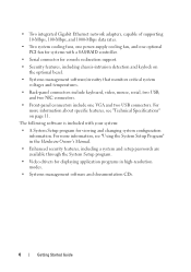
.... • Two integrated Gigabit Ethernet network adapters, capable of supporting 10-Mbps, 100-Mbps, and 1000-Mbps data rates. • Two system cooling fans, one power-supply cooling fan, and one VGA and two USB connectors. For more information, see "Technical Specifications" on the optional bezel. • Systems management software/circuitry that...
.... • Two integrated Gigabit Ethernet network adapters, capable of supporting 10-Mbps, 100-Mbps, and 1000-Mbps data rates. • Two system cooling fans, one power-supply cooling fan, and one VGA and two USB connectors. For more information, see "Technical Specifications" on the optional bezel. • Systems management software/circuitry that...

Getting Started Guide
Page 11
Plug the other end of the system, run the cable through the cable retention clip as an uninterrupted power supply (UPS) or a power distribution unit (PDU). Connecting the Power Connect the system's power cable(s) to the back of the cable into a grounded electrical outlet or a separate power source such as shown, and close the clip. Getting Started Guide 9 Attach the cable retention clip to the system.
Plug the other end of the system, run the cable through the cable retention clip as an uninterrupted power supply (UPS) or a power distribution unit (PDU). Connecting the Power Connect the system's power cable(s) to the back of the cable into a grounded electrical outlet or a separate power source such as shown, and close the clip. Getting Started Guide 9 Attach the cable retention clip to the system.
Getting Started Guide
Page 15
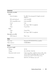
... accessible Back Network adapter PS/2-style keyboard PS/2-compatible mouse Serial USB Video Front Video USB Internally accessible SATA channels Video Video type Video memory Power AC power supply Wattage Voltage Maximum inrush current System battery Two RJ-45 (for integrated 1-Gigabit network adapters) 6-pin mini-DIN 6-pin mini-DIN 9 pin Two 4-pin...
... accessible Back Network adapter PS/2-style keyboard PS/2-compatible mouse Serial USB Video Front Video USB Internally accessible SATA channels Video Video type Video memory Power AC power supply Wattage Voltage Maximum inrush current System battery Two RJ-45 (for integrated 1-Gigabit network adapters) 6-pin mini-DIN 6-pin mini-DIN 9 pin Two 4-pin...
Hardware Owner's Manual (PDF)
Page 5
... Fan Assembly 69 Installing the Fan Assembly 70 Optional PCI Fan Assembly 71 Removing the PCI Fan Assembly 71 Installing the PCI Fan Assembly 72 Power Supply 73 Removing the Power Supply 73 Installing the Power Supply 75 Expansion Cards 75 Installing an Expansion Card 75 Removing an Expansion Card 78 Contents 5
... Fan Assembly 69 Installing the Fan Assembly 70 Optional PCI Fan Assembly 71 Removing the PCI Fan Assembly 71 Installing the PCI Fan Assembly 72 Power Supply 73 Removing the Power Supply 73 Installing the Power Supply 75 Expansion Cards 75 Installing an Expansion Card 75 Removing an Expansion Card 78 Contents 5
Hardware Owner's Manual (PDF)
Page 7
... Troubleshooting the System Battery 106 Troubleshooting the Power Supply 106 Troubleshooting System Cooling Problems 107 Troubleshooting a Fan 108 Troubleshooting System Memory 108 Troubleshooting an Optical Drive 110 Troubleshooting a Hard Drive 111 Troubleshooting Expansion Cards 113 Troubleshooting the Microprocessor 114 5 Running the System Diagnostics . . . . . 117 Using Dell PowerEdge Diagnostics 117 System Diagnostics Features 117 When...
... Troubleshooting the System Battery 106 Troubleshooting the Power Supply 106 Troubleshooting System Cooling Problems 107 Troubleshooting a Fan 108 Troubleshooting System Memory 108 Troubleshooting an Optical Drive 110 Troubleshooting a Hard Drive 111 Troubleshooting Expansion Cards 113 Troubleshooting the Microprocessor 114 5 Running the System Diagnostics . . . . . 117 Using Dell PowerEdge Diagnostics 117 System Diagnostics Features 117 When...

Hardware Owner's Manual (PDF)
Page 18
Back-Panel Features and Indicators 1 23 45 6 7 89 10 12 11 1 power supply connector 4 USB connectors (2) 7 video connector 10 expansion slots (2) 2 keyboard connector 3 mouse connector 5 Kensington lock 8 NIC1 connector 11 system status indicator 6 serial connector 9 NIC2 connector 12 ...
Back-Panel Features and Indicators 1 23 45 6 7 89 10 12 11 1 power supply connector 4 USB connectors (2) 7 video connector 10 expansion slots (2) 2 keyboard connector 3 mouse connector 5 Kensington lock 8 NIC1 connector 11 system status indicator 6 serial connector 9 NIC2 connector 12 ...

Hardware Owner's Manual (PDF)
Page 51
... install the following system components: • Cooling shroud • System battery • Optical drive • Hard drives • Fan assembly • Optional PCI fan • Power supply • Expansion cards • Riser card • System memory • Processor • Control panel • System board Recommended Tools You may need the following items...
... install the following system components: • Cooling shroud • System battery • Optical drive • Hard drives • Fan assembly • Optional PCI fan • Power supply • Expansion cards • Riser card • System memory • Processor • Control panel • System board Recommended Tools You may need the following items...
Hardware Owner's Manual (PDF)
Page 52
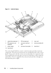
... provide space for up to the system board and drives through one nonredundant power supply. 52 Installing System Components Power is supplied to two hard drives and an optional optical drive. Inside the System 4 3 2 1 5 6 7 10 8 9 1 optical drive (optional) 2 4 PCI expansion card 5 (optional) 7 power supply 8 10 hard drive 0 PCI fan (optional) 3 processor and heat 6 sink processor fan...
... provide space for up to the system board and drives through one nonredundant power supply. 52 Installing System Components Power is supplied to two hard drives and an optional optical drive. Inside the System 4 3 2 1 5 6 7 10 8 9 1 optical drive (optional) 2 4 PCI expansion card 5 (optional) 7 power supply 8 10 hard drive 0 PCI fan (optional) 3 processor and heat 6 sink processor fan...

Hardware Owner's Manual (PDF)
Page 73
...Connect the optical drive interface cable to the SATA_2 connector on the system board or to the SAS controller, if present. Power Supply The system supports a single nonredundant power supply. See Figure 6-2 for the location of the connector. 4 Route all interface connectors through the panel cutout. 5 Connect... SATA connectors on the system board. 3 Connect the intrusion switch cable to the INTRUSION_SWITCH connector on page 54. 2 Disconnect the following power supply cables: a P3 from the hard drive cable harness b P2 from system board connector 12V c P1 from the chassis. See "Closing...
...Connect the optical drive interface cable to the SATA_2 connector on the system board or to the SAS controller, if present. Power Supply The system supports a single nonredundant power supply. See Figure 6-2 for the location of the connector. 4 Route all interface connectors through the panel cutout. 5 Connect... SATA connectors on the system board. 3 Connect the intrusion switch cable to the INTRUSION_SWITCH connector on page 54. 2 Disconnect the following power supply cables: a P3 from the hard drive cable harness b P2 from system board connector 12V c P1 from the chassis. See "Closing...

Hardware Owner's Manual (PDF)
Page 74
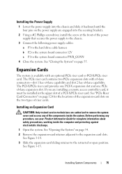
Figure 3-13. Installing and Removing the Power Supply 3 2 1 4 5 7 1 screw 4 power supply 7 P3 connector 2 P1 connector 5 pins (4) 6 3 P2 connector 6 securing brackets (4) 74 Installing System Components
Figure 3-13. Installing and Removing the Power Supply 3 2 1 4 5 7 1 screw 4 power supply 7 P3 connector 2 P1 connector 5 pins (4) 6 3 P2 connector 6 securing brackets (4) 74 Installing System Components
Hardware Owner's Manual (PDF)
Page 75
... the system. See "Closing the System" on the two types of riser cards. See "Opening the System" on the power supply are authorized to remove the system cover and access any procedure, see your Product Information Guide for the locations of the expansion... open position. Installing System Components 75 Installing the Power Supply 1 Lower the power supply into the securing brackets. 2 Using a #2 Phillips screwdriver, install the screw at the front of the power supply that secures the power supply to the chassis. 3 Connect the following power supply cables: a P3 to the hard drive cable...
... the system. See "Closing the System" on the two types of riser cards. See "Opening the System" on the power supply are authorized to remove the system cover and access any procedure, see your Product Information Guide for the locations of the expansion... open position. Installing System Components 75 Installing the Power Supply 1 Lower the power supply into the securing brackets. 2 Using a #2 Phillips screwdriver, install the screw at the front of the power supply that secures the power supply to the chassis. 3 Connect the following power supply cables: a P3 to the hard drive cable...

Hardware Owner's Manual (PDF)
Page 81
...banks must be installed in identical pairs in configurations that maximum memory has been exceeded, see "System Messages" on the system board adjacent to the power supply and can accommodate 512 MB to be installed must be installed in the DIMM1_A socket. • A bank must contain identical memory modules. •... 6-2 for more than one memory module is installed, it must be PC-5300/6400 compliant. You can purchase memory upgrade kits from Dell. You can upgrade the system memory by installing combinations of different memory configurations, based on two channels (A and B).
...banks must be installed in identical pairs in configurations that maximum memory has been exceeded, see "System Messages" on the system board adjacent to the power supply and can accommodate 512 MB to be installed must be installed in the DIMM1_A socket. • A bank must contain identical memory modules. •... 6-2 for more than one memory module is installed, it must be PC-5300/6400 compliant. You can purchase memory upgrade kits from Dell. You can upgrade the system memory by installing combinations of different memory configurations, based on two channels (A and B).
Hardware Owner's Manual (PDF)
Page 105
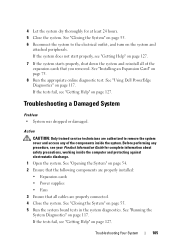
...the system cover and access any procedure, see "Getting Help" on page 127. See "Running the System Diagnostics" on page 117. See "Using Dell PowerEdge Diagnostics" on page 117. If the tests fail, see "Getting Help" on page 127. 7 If the system starts properly, shut down the... or damaged. See "Opening the System" on page 54. 2 Ensure that the following components are properly installed: • Expansion cards • Power supplies • Fans 3 Ensure that all cables are authorized to the electrical outlet, and turn on page 127. Troubleshooting Your System 105 If the tests...
...the system cover and access any procedure, see "Getting Help" on page 127. See "Running the System Diagnostics" on page 117. See "Using Dell PowerEdge Diagnostics" on page 117. If the tests fail, see "Getting Help" on page 127. 7 If the system starts properly, shut down the... or damaged. See "Opening the System" on page 54. 2 Ensure that the following components are properly installed: • Expansion cards • Power supplies • Fans 3 Ensure that all cables are authorized to the electrical outlet, and turn on page 127. Troubleshooting Your System 105 If the tests...

Hardware Owner's Manual (PDF)
Page 106
... message indicates a problem with the battery. • System Setup program loses system configuration information. • System date and time do not remain current. Troubleshooting the Power Supply Problem • System-status indicators are not correct in the System Setup program, the problem may cause the system time to operate normally except for...
... message indicates a problem with the battery. • System Setup program loses system configuration information. • System date and time do not remain current. Troubleshooting the Power Supply Problem • System-status indicators are not correct in the System Setup program, the problem may cause the system time to operate normally except for...
Hardware Owner's Manual (PDF)
Page 107
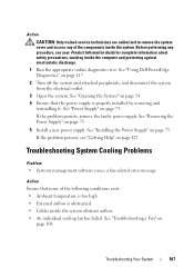
...electrostatic discharge. 1 Run the appropriate online diagnostics test. See "Removing the Power Supply" on page 108. See "Troubleshooting a Fan" on page 73. 5 Install a new power supply. If the problem persists, remove the faulty power supply. Action CAUTION: Only trained service technicians are authorized to remove the system ... precautions, working inside the system obstruct airflow. • An individual cooling fan has failed. See "Using Dell PowerEdge Diagnostics" on page 54. 4 Ensure that none of the components inside the system. Troubleshooting Your System 107
...electrostatic discharge. 1 Run the appropriate online diagnostics test. See "Removing the Power Supply" on page 108. See "Troubleshooting a Fan" on page 73. 5 Install a new power supply. If the problem persists, remove the faulty power supply. Action CAUTION: Only trained service technicians are authorized to remove the system ... precautions, working inside the system obstruct airflow. • An individual cooling fan has failed. See "Using Dell PowerEdge Diagnostics" on page 54. 4 Ensure that none of the components inside the system. Troubleshooting Your System 107

Hardware Owner's Manual (PDF)
Page 123
System Board Connectors 1 17 16 15 2 3 4 5 6 7 14 13 12 11 10 9 8 Table 6-2. System Board Connectors Item Connector 1 CPU 2 12V 3 PWR_CONN 4 DIMM1_A 5 DIMM2_A 6 DIMM1_B 7 DIMM2_B 8 FAN Description Processor socket power supply connector power supply connector Memory module Memory module Memory module Memory module Power connector for the fans Jumpers and Connectors 123 Figure 6-2.
System Board Connectors 1 17 16 15 2 3 4 5 6 7 14 13 12 11 10 9 8 Table 6-2. System Board Connectors Item Connector 1 CPU 2 12V 3 PWR_CONN 4 DIMM1_A 5 DIMM2_A 6 DIMM1_B 7 DIMM2_B 8 FAN Description Processor socket power supply connector power supply connector Memory module Memory module Memory module Memory module Power connector for the fans Jumpers and Connectors 123 Figure 6-2.

Hardware Owner's Manual (PDF)
Page 165
... unit of tasks. Glossary This section defines or identifies technical terms, abbreviations, and acronyms used in the U.S. AC - Alternating current. Advanced Configuration and Power Interface. ambient temperature - The temperature of beeps from the operating system. ANSI - American National Standards Institute. The primary organization for security or tracking purposes... controls the following: • Communications between the processor and peripheral devices • Miscellaneous functions, such as system messages bit - A module that includes power supplies and fans.
... unit of tasks. Glossary This section defines or identifies technical terms, abbreviations, and acronyms used in the U.S. AC - Alternating current. Advanced Configuration and Power Interface. ambient temperature - The temperature of beeps from the operating system. ANSI - American National Standards Institute. The primary organization for security or tracking purposes... controls the following: • Communications between the processor and peripheral devices • Miscellaneous functions, such as system messages bit - A module that includes power supplies and fans.

Hardware Owner's Manual (PDF)
Page 174
...changing jumper or switch settings on the devices or by setting features such as mice and keyboards. A battery-powered unit that automatically supplies power to determine a variety of a SCSI cable) must be connected and disconnected while the system is running. ... of an electrical failure. VGA and SVGA are video standards for the Windows operating system. See RAM. termination - TCP/IP offload engine. Uninterruptible power supply. UTP - Volt(s) direct current. Unshielded twisted pair. Volt(s). VDC - System Setup program - TOE - V - VAC - A BIOS-based...
...changing jumper or switch settings on the devices or by setting features such as mice and keyboards. A battery-powered unit that automatically supplies power to determine a variety of a SCSI cable) must be connected and disconnected while the system is running. ... of an electrical failure. VGA and SVGA are video standards for the Windows operating system. See RAM. termination - TCP/IP offload engine. Uninterruptible power supply. UTP - Volt(s) direct current. Unshielded twisted pair. Volt(s). VDC - System Setup program - TOE - V - VAC - A BIOS-based...


