
Information and Firmware Update
Page 3
...Dell OpenManage Server Administrator 1-2 Updating the System Management Module Firmware 1-3 Updating the KVM Firmware 1-4 Updating the System Management Module KVM Firmware . . 1-5 Globally Updating the Server Module KVM Firmware . . . . . 1-6 Individually Updating the Server Module KVM Firmware . . . 1-6 Updating the Network Switch... Module Firmware 1-7 Setting Up the Remote System Serial Connection Baud Rate . . 1-7 Configuring the Network Switch Module 1-8 Updating the Diagnostics Component 1-9 Updating the Loader Component...
...Dell OpenManage Server Administrator 1-2 Updating the System Management Module Firmware 1-3 Updating the KVM Firmware 1-4 Updating the System Management Module KVM Firmware . . 1-5 Globally Updating the Server Module KVM Firmware . . . . . 1-6 Individually Updating the Server Module KVM Firmware . . . 1-6 Updating the Network Switch... Module Firmware 1-7 Setting Up the Remote System Serial Connection Baud Rate . . 1-7 Configuring the Network Switch Module 1-8 Updating the Diagnostics Component 1-9 Updating the Loader Component...
Information and Firmware Update
Page 4
... in a Mirrored Configuration . . . . . . 1-15 1-15 1-16 Online Diagnostics SCSI Controller Test Issue When Using a Linux Console 1-16 SCSI Device Errors During System Boot 1-17 Using a Dell-Branded Logitech PS/2 Mouse 1-17 Figures Figure 1-1. Figure 1-4. Figure 1-3. Integrated Mirroring Issues Replacing a System Board When Mirroring Is Enabled . . . . Figure 1-2. Attaching the Drive Shelf Steps...
... in a Mirrored Configuration . . . . . . 1-15 1-15 1-16 Online Diagnostics SCSI Controller Test Issue When Using a Linux Console 1-16 SCSI Device Errors During System Boot 1-17 Using a Dell-Branded Logitech PS/2 Mouse 1-17 Figures Figure 1-1. Figure 1-4. Figure 1-3. Integrated Mirroring Issues Replacing a System Board When Mirroring Is Enabled . . . . Figure 1-2. Attaching the Drive Shelf Steps...
Information and Firmware Update
Page 5
... system BIOS from diskettes • Updating the system BIOS with Dell OpenManage™ Server Administrator • Updating the system management module firmware • Updating the KVM firmware • Updating the network switch module firmware • Replacing the server module battery • Using... Using the system management module to manage server modules • System management module time issues • Logging out of a network switch module HTTP session • Integrated mirroring issues • Online diagnostics SCSI controller test issue when using a Linux console • ...
... system BIOS from diskettes • Updating the system BIOS with Dell OpenManage™ Server Administrator • Updating the system management module firmware • Updating the KVM firmware • Updating the network switch module firmware • Replacing the server module battery • Using... Using the system management module to manage server modules • System management module time issues • Logging out of a network switch module HTTP session • Integrated mirroring issues • Online diagnostics SCSI controller test issue when using a Linux console • ...
Information and Firmware Update
Page 11
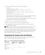
... However, step 2 through step 8 are referenced in each of the network switch module can be updated by typing show version from the Dell Support website at support.dell.com with updating the network switch module firmware. Setting Up the Remote System Serial Connection Baud Rate This procedure... serial connection baud rate for the new connection. 3 On the HyperTerminal toolbar, click Disconnect to disconnect the serial connection to the network switch module. 4 On the HyperTerminal toolbar, click Properties. 5 From the Properties dialog box, click Configure and set up the COM port as...
... However, step 2 through step 8 are referenced in each of the network switch module can be updated by typing show version from the Dell Support website at support.dell.com with updating the network switch module firmware. Setting Up the Remote System Serial Connection Baud Rate This procedure... serial connection baud rate for the new connection. 3 On the HyperTerminal toolbar, click Disconnect to disconnect the serial connection to the network switch module. 4 On the HyperTerminal toolbar, click Properties. 5 From the Properties dialog box, click Configure and set up the COM port as...
Information and Firmware Update
Page 12
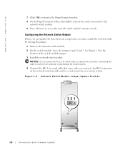
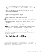
... to the RJ-11 connector on the network switch module and to access the network switch module's remote console. Network Switch Module Jumper Update Position 1-8 Information and Firmware Update See Figure 1-3 for the location of the switch module jumper. 3 Install the network switch module. www.dell.com | support.dell.com 7 Click OK to return to the HyperTerminal...
... to the RJ-11 connector on the network switch module and to access the network switch module's remote console. Network Switch Module Jumper Update Position 1-8 Information and Firmware Update See Figure 1-3 for the location of the switch module jumper. 3 Install the network switch module. www.dell.com | support.dell.com 7 Click OK to return to the HyperTerminal...
Information and Firmware Update
Page 13
...remote system's baud rate to 115200 (see "Setting Up the Remote System Serial Connection Baud Rate"). 12 To update other components, remove the network switch module and move the jumper back to pins 1 and 2 (default). If you wait too long and your operating system begins to load let the... be able to use ERA/MC console redirection to log into the network switch module. Updating the Loader Component 1 With the RJ-11-to-serial cable connected to the network switch module, reset the switch module by unplugging the switch module and then reinserting it . 2 During POST, press to enter the...
...remote system's baud rate to 115200 (see "Setting Up the Remote System Serial Connection Baud Rate"). 12 To update other components, remove the network switch module and move the jumper back to pins 1 and 2 (default). If you wait too long and your operating system begins to load let the... be able to use ERA/MC console redirection to log into the network switch module. Updating the Loader Component 1 With the RJ-11-to-serial cable connected to the network switch module, reset the switch module by unplugging the switch module and then reinserting it . 2 During POST, press to enter the...
Information and Firmware Update
Page 14
...where xxx is updated using the R-J11-to-serial cable. 1 With the RJ-11-to-serial cable connected to the network switch module, reset the switch module by unplugging the switch module and then reinserting it. 2 During POST, press to the remote system (TFTP server). It is recommended that the runtime...do not move the jumper back to -serial cable or the 10/100/1000 BASE-T uplink ports. www.dell.com | support.dell.com 3 Type 0 (zero) for more information about updating the switch module firmware. Updating the Runtime Component NOTE: The runtime component can be able to use ERA/MC console ...
...where xxx is updated using the R-J11-to-serial cable. 1 With the RJ-11-to-serial cable connected to the network switch module, reset the switch module by unplugging the switch module and then reinserting it. 2 During POST, press to the remote system (TFTP server). It is recommended that the runtime...do not move the jumper back to -serial cable or the 10/100/1000 BASE-T uplink ports. www.dell.com | support.dell.com 3 Type 0 (zero) for more information about updating the switch module firmware. Updating the Runtime Component NOTE: The runtime component can be able to use ERA/MC console ...
Information and Firmware Update
Page 15
... ERA/MC console redirection to pins 1 and 2 (default). NOTE: If you do not move the jumper back to log into the network switch module. Replacing the Server Module Battery CAUTION: Only trained service technicians are not updating any key to continue, and proceed to "Updating the Diagnostics... 9600 (see "Setting Up the Remote System Serial Connection Baud Rate"). 12 To update other components, press any other components, remove the network switch module and move the jumper back to pins 1 and 2, you are authorized to download the file. See your System Information Guide for complete...
... ERA/MC console redirection to pins 1 and 2 (default). NOTE: If you do not move the jumper back to log into the network switch module. Replacing the Server Module Battery CAUTION: Only trained service technicians are not updating any key to continue, and proceed to "Updating the Diagnostics... 9600 (see "Setting Up the Remote System Serial Connection Baud Rate"). 12 To update other components, press any other components, remove the network switch module and move the jumper back to pins 1 and 2, you are authorized to download the file. See your System Information Guide for complete...
Information and Firmware Update
Page 19
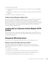
...mirroring are displayed. If the time is not set the system management module's time as soon as possible after connecting the system to the network switch module and using a Web console HTTP session, you out. If the integrated mirroring option is stored on . This will be corrected in ...USB diskette drive. 4 Connect the USB diskette drive to the server module and turn it on the system board. Logging Out of a Network Switch Module HTTP Session When connected to AC power, resetting the system management module, or updating the firmware. Replacing a System Board When Mirroring Is...
...mirroring are displayed. If the time is not set the system management module's time as soon as possible after connecting the system to the network switch module and using a Web console HTTP session, you out. If the integrated mirroring option is stored on . This will be corrected in ...USB diskette drive. 4 Connect the USB diskette drive to the server module and turn it on the system board. Logging Out of a Network Switch Module HTTP Session When connected to AC power, resetting the system management module, or updating the firmware. Replacing a System Board When Mirroring Is...

System Configuration Guide
Page 3
... 1-7 Integrating the System Into the Network 1-9 Configuring a Static Channel 1-12 Configuring a Dynamic Channel 1-13 Using the KVM Switch Viewing and Selecting Ports and Servers Selecting Servers Soft Switching OSCAR Navigation Basics Configuring OSCAR Assigning Server Names Changing the Display Behavior Setting OSCAR Screen Saver Security 1-14 1-16 1-17 1-17 1-18 1-19 1-19...
... 1-7 Integrating the System Into the Network 1-9 Configuring a Static Channel 1-12 Configuring a Dynamic Channel 1-13 Using the KVM Switch Viewing and Selecting Ports and Servers Selecting Servers Soft Switching OSCAR Navigation Basics Configuring OSCAR Assigning Server Names Changing the Display Behavior Setting OSCAR Screen Saver Security 1-14 1-16 1-17 1-17 1-18 1-19 1-19...
System Configuration Guide
Page 4
... Back-Panel Features System Management Module Features . . . . . Figure 1-3. Icons on Network Switch OSCAR Navigation Keys Setup Features to Two External Switches Managing the System With the Onboard KVM Switch Managing the System With an Analog KVM Switch Managing the System With a KVM-Over-IP Switch 1-1 1-2 1-5 1-8 1-11 1-14 1-15 1-15 1-16 Tables Table 1-1. Figure 1-9. Table 1-5. Internal...
... Back-Panel Features System Management Module Features . . . . . Figure 1-3. Icons on Network Switch OSCAR Navigation Keys Setup Features to Two External Switches Managing the System With the Onboard KVM Switch Managing the System With an Analog KVM Switch Managing the System With a KVM-Over-IP Switch 1-1 1-2 1-5 1-8 1-11 1-14 1-15 1-15 1-16 Tables Table 1-1. Figure 1-9. Table 1-5. Internal...
System Configuration Guide
Page 5
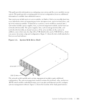
... remote access circuitry and firmware used to six server modules (or blades). The power supplies, fans, system management module, and network switch module are shared resources of the back-panel features. Figure 1-1 shows the drive shelf attached so that includes power supplies, fans, ...a system management module, and at least one network switch module. To function as an individual system encompassing up to two microprocessors, up to two hard drives, and up to configure systems management...
... remote access circuitry and firmware used to six server modules (or blades). The power supplies, fans, system management module, and network switch module are shared resources of the back-panel features. Figure 1-1 shows the drive shelf attached so that includes power supplies, fans, ...a system management module, and at least one network switch module. To function as an individual system encompassing up to two microprocessors, up to two hard drives, and up to configure systems management...
System Configuration Guide
Page 6
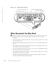
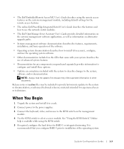
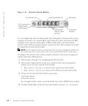
Back-Panel Features network switch module 1 network switch module 2 system management module power supplies (2) fans (4) Other Documents You May Need The System Information Guide provides important safety and regulatory information. www.dell.com | support.dell.com Figure 1-2. Warranty information...BIOS settings and defaults, and technical specifications. • The Dell OpenManage Remote Install User's Guide describes imaging a server module configuration to another server module. • The Dell PowerEdge Expandable RAID Controller 4/im Integrated Mirroring Guide describes using the ...
Back-Panel Features network switch module 1 network switch module 2 system management module power supplies (2) fans (4) Other Documents You May Need The System Information Guide provides important safety and regulatory information. www.dell.com | support.dell.com Figure 1-2. Warranty information...BIOS settings and defaults, and technical specifications. • The Dell OpenManage Remote Install User's Guide describes imaging a server module configuration to another server module. • The Dell PowerEdge Expandable RAID Controller 4/im Integrated Mirroring Guide describes using the ...
System Configuration Guide
Page 7
..., including default settings for the remote access features. • The online Dell PowerEdge Integrated Switch User's Guide describes the features and how to use the network switch modules. • The Dell OpenManage Server Assistant User's Guide provides detailed information on the systems management software...included to provide last-minute updates to select a server module. See "Using the KVM Switch." • The Dell Embedded Remote Access/MC User's Guide describes using the KVM switch. 5 If required, configure the hard drives for experienced users or technicians. NOTE: Always...
..., including default settings for the remote access features. • The online Dell PowerEdge Integrated Switch User's Guide describes the features and how to use the network switch modules. • The Dell OpenManage Server Assistant User's Guide provides detailed information on the systems management software...included to provide last-minute updates to select a server module. See "Using the KVM Switch." • The Dell Embedded Remote Access/MC User's Guide describes using the KVM switch. 5 If required, configure the hard drives for experienced users or technicians. NOTE: Always...
System Configuration Guide
Page 8
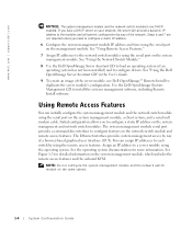
... module. See the operating system documentation for detailed information on the system management and network switch modules. www.dell.com | support.dell.com NOTICE: The system management module and the network switch module(s) are not required unless you need to configure a static IP address. 6 Configure...the User's Guide. 9 To create an image of a browser-based graphical user interface (GUI). Use the Dell OpenManage Systems Management CD to each switch by using the operating system. Using Remote Access Features You can assign IP addresses to install the systems management software...
... module. See the operating system documentation for detailed information on the system management and network switch modules. www.dell.com | support.dell.com NOTICE: The system management module and the network switch module(s) are not required unless you need to configure a static IP address. 6 Configure...the User's Guide. 9 To create an image of a browser-based graphical user interface (GUI). Use the Dell OpenManage Systems Management CD to each switch by using the operating system. Using Remote Access Features You can assign IP addresses to install the systems management software...
System Configuration Guide
Page 9
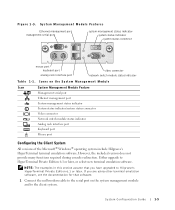
...Module Icon System Management Module Feature Management serial port Ethernet management port System management status indicator System status indicator/system status connector Video connector Network switch module status indicator Analog rack interface port Keyboard port Mouse port Configuring the Client System All versions of the Microsoft® Windows® operating... serial port system management status indicator system status indicator system status connector mouse port keyboard port analog rack interface port video connector network switch module status indicator Table 1-1.
...Module Icon System Management Module Feature Management serial port Ethernet management port System management status indicator System status indicator/system status connector Video connector Network switch module status indicator Analog rack interface port Keyboard port Mouse port Configuring the Client System All versions of the Microsoft® Windows® operating... serial port system management status indicator system status indicator system status connector mouse port keyboard port analog rack interface port video connector network switch module status indicator Table 1-1.
System Configuration Guide
Page 11
...) accesses LOM2 on using these utilities, see the Dell Embedded Remote Access/MC User's Guide and online help. After setting the IP address on a network switch module. For additional information on all of the server modules; The current and static IP addresses are displayed. 19 Type ... recommended that is the local time minus Greenwich Mean Time (GMT) in seconds and offset is shipped with your switch (for example, port management or VLANs), see the Dell Embedded Remote Access/MC User's Guide. System Configuration Guide 1-7 15 At the serial command prompt for the location...
...) accesses LOM2 on using these utilities, see the Dell Embedded Remote Access/MC User's Guide and online help. After setting the IP address on a network switch module. For additional information on all of the server modules; The current and static IP addresses are displayed. 19 Type ... recommended that is the local time minus Greenwich Mean Time (GMT) in seconds and offset is shipped with your switch (for example, port management or VLANs), see the Dell Embedded Remote Access/MC User's Guide. System Configuration Guide 1-7 15 At the serial command prompt for the location...
System Configuration Guide
Page 12
www.dell.com | support.dell.com Figure 1-4. Dell recommends using the RJ11 serial null modem cable connected to the RJ11 serial port on the network switch module. NOTE: Do not connect the RJ11 configuration port to the network switch module console, type: Username-admin Password-admin You are logged.... Do not connect the RJ11 serial cable to any of the network switch modules. • Type connect switch-1 to connect to the top network switch module. • Type connect switch-2 to connect to the bottom network switch module. 3 To log on the system management module to -RJ11 cable is...
www.dell.com | support.dell.com Figure 1-4. Dell recommends using the RJ11 serial null modem cable connected to the RJ11 serial port on the network switch module. NOTE: Do not connect the RJ11 configuration port to the network switch module console, type: Username-admin Password-admin You are logged.... Do not connect the RJ11 serial cable to any of the network switch modules. • Type connect switch-1 to connect to the top network switch module. • Type connect switch-2 to connect to the bottom network switch module. 3 To log on the system management module to -RJ11 cable is...
System Configuration Guide
Page 13
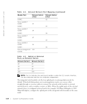
...detailed information on configuration. After the network switch module is present), perform the previous configuration steps. See the online Dell PowerEdge Integrated Switch User's Guide for the configuration. 6 Type quit or exit to logout of the serial switch console. 7 Type ~. Table 1-2 and...It is essentially a self-contained network. For further information, see the Dell PowerEdge Integrated Switch User's Guide. Table 1-2. Integrating the System Into the Network The Dell™ PowerEdge™ 1655MC is recommended that you may use the browser-based GUI, Telnet consoles...
...detailed information on configuration. After the network switch module is present), perform the previous configuration steps. See the online Dell PowerEdge Integrated Switch User's Guide for the configuration. 6 Type quit or exit to logout of the serial switch console. 7 Type ~. Table 1-2 and...It is essentially a self-contained network. For further information, see the Dell PowerEdge Integrated Switch User's Guide. Table 1-2. Integrating the System Into the Network The Dell™ PowerEdge™ 1655MC is recommended that you may use the browser-based GUI, Telnet consoles...
System Configuration Guide
Page 14
... or External Ports on Network Switch Network Switch 1 Network Switch 2 1/7 1/7 1/8 1/8 1/9 1/9 1/10 1/10 NOTE: The 1/x indicates the switch port number x under the ...-duplex or 1000 Mbps full-duplex), configure the uplink ports of the integrated switch module in autonegotiation mode by default. Internal Network Port Mapping (continued) Module ...6 LOM 1 LOM 2 System management module Network Switch 1 Port 1/3 1/4 1/5 1/6 1/11 Network Switch 2 Port 1/2 1/3 1/4 1/5 1/6 Table 1-3. The integrated switch module sets the four uplink ports in the same mode. 1-10 ...
... or External Ports on Network Switch Network Switch 1 Network Switch 2 1/7 1/7 1/8 1/8 1/9 1/9 1/10 1/10 NOTE: The 1/x indicates the switch port number x under the ...-duplex or 1000 Mbps full-duplex), configure the uplink ports of the integrated switch module in autonegotiation mode by default. Internal Network Port Mapping (continued) Module ...6 LOM 1 LOM 2 System management module Network Switch 1 Port 1/3 1/4 1/5 1/6 1/11 Network Switch 2 Port 1/2 1/3 1/4 1/5 1/6 Table 1-3. The integrated switch module sets the four uplink ports in the same mode. 1-10 ...


