Service Manual
Page 11
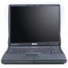
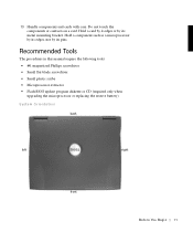
... in this manual require the following tools: • #1 magnetized Phillips screwdriver • Small flat-blade screwdriver • Small plastic scribe • Microprocessor extractor • Flash BIOS update program diskette or CD (required only when upgrading the microprocessor or replacing the reserve battery) System Orientation back left right front B e fo re You...
... in this manual require the following tools: • #1 magnetized Phillips screwdriver • Small flat-blade screwdriver • Small plastic scribe • Microprocessor extractor • Flash BIOS update program diskette or CD (required only when upgrading the microprocessor or replacing the reserve battery) System Orientation back left right front B e fo re You...
Service Manual
Page 49
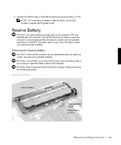
... battery connector Removing and Repl aci ng Part s 49 NOTICE: Read "Preparing to update or flash the BIOS, see the Dell Portable Computer BIOS Update Guide. 3 Update the BIOS using a wrist grounding strap or by using a flash BIOS update program diskette or CD. NOTE: For instructions to Work Inside the Computer" before you remove the... off. Reserve Battery NOTICE: The reserve battery provides power to lose the date and time information as well as all user-specified parameters in the BIOS.
... battery connector Removing and Repl aci ng Part s 49 NOTICE: Read "Preparing to update or flash the BIOS, see the Dell Portable Computer BIOS Update Guide. 3 Update the BIOS using a wrist grounding strap or by using a flash BIOS update program diskette or CD. NOTE: For instructions to Work Inside the Computer" before you remove the... off. Reserve Battery NOTICE: The reserve battery provides power to lose the date and time information as well as all user-specified parameters in the BIOS.
Service Manual
Page 50
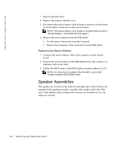
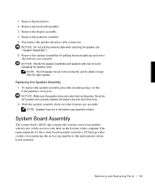
... speaker assembly is not located on the system board assembly located next to update or flash the BIOS, see the Dell Portable Computer BIOS Update Guide. Take note of the bottom case assembly. www.dell.com | support.dell.com 1 Remove the hard drive. 2 Remove the memory module cover. 3 Disconnect the reserve battery cable from the...
... speaker assembly is not located on the system board assembly located next to update or flash the BIOS, see the Dell Portable Computer BIOS Update Guide. Take note of the bottom case assembly. www.dell.com | support.dell.com 1 Remove the hard drive. 2 Remove the memory module cover. 3 Disconnect the reserve battery cable from the...
Service Manual
Page 53
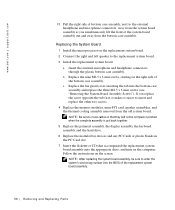
... drive. 2 Remove the keyboard assembly. 3 Remove the display assembly. 4 Remove the palmrest assembly. 5 Disconnect the speaker interface cable connectors. System Board Assembly The system board's BIOS chip contains the system's service tag number, which is longer than the right speaker. NOTE: The left speaker wire properly between the battery bay and...
... drive. 2 Remove the keyboard assembly. 3 Remove the display assembly. 4 Remove the palmrest assembly. 5 Disconnect the speaker interface cable connectors. System Board Assembly The system board's BIOS chip contains the system's service tag number, which is longer than the right speaker. NOTE: The left speaker wire properly between the battery bay and...
Service Manual
Page 56
... PC Card slot. 7 Insert the diskette or CD that they will not be sure to enter the system's service tag number into the BIOS of the replacement system board assembly. 56 Removi ng and Replacing Parts a Insert the external microphone and headphone connectors through the plastic bottom case... assembly into the bottom case assembly and replace the three M2.5 x 5-mm screws (see "Removing the System Board Assembly Screws"). www.dell.com | support.dell.com 13 Pull the right side of bottom case assembly, next to the external headphone and microphone connectors, away from the system board assembly...
... PC Card slot. 7 Insert the diskette or CD that they will not be sure to enter the system's service tag number into the BIOS of the replacement system board assembly. 56 Removi ng and Replacing Parts a Insert the external microphone and headphone connectors through the plastic bottom case... assembly into the bottom case assembly and replace the three M2.5 x 5-mm screws (see "Removing the System Board Assembly Screws"). www.dell.com | support.dell.com 13 Pull the right side of bottom case assembly, next to the external headphone and microphone connectors, away from the system board assembly...


