Service Manual
Page 5
... and Replacing Parts Components 16 Hard Drive 17 Removing the Hard Drive 17 Replacing the Hard Drive 17 Memory Module 18 Removing the Memory Module Cover 18 Removing the Memory Modules 19 Replacing the Memory Modules 20 Mini-PCI Card Assembly 20 Removing the Mini-PCI Card Assembly 22 Replacing the Mini-PCI Card...
... and Replacing Parts Components 16 Hard Drive 17 Removing the Hard Drive 17 Replacing the Hard Drive 17 Memory Module 18 Removing the Memory Module Cover 18 Removing the Memory Modules 19 Replacing the Memory Modules 20 Mini-PCI Card Assembly 20 Removing the Mini-PCI Card Assembly 22 Replacing the Mini-PCI Card...

Service Manual
Page 15
SECTION 2 Removing and Replacing Parts Components Hard Drive Memory Module Mini-PCI Card Assembly Keyboard Assembly Removing the Display Assembly Display Assembly Latch Hinge Covers Palmrest Assembly Microprocessor Thermal Cooling Assembly Hybrid Cooling Fan Microprocessor Module Reserve Battery Speaker Assemblies System Board Assembly Battery and Modular Bay Latch Assemblies www.dell.com | support.dell.com
SECTION 2 Removing and Replacing Parts Components Hard Drive Memory Module Mini-PCI Card Assembly Keyboard Assembly Removing the Display Assembly Display Assembly Latch Hinge Covers Palmrest Assembly Microprocessor Thermal Cooling Assembly Hybrid Cooling Fan Microprocessor Module Reserve Battery Speaker Assemblies System Board Assembly Battery and Modular Bay Latch Assemblies www.dell.com | support.dell.com
Service Manual
Page 16
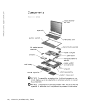
...and Replacing Parts Damage due to servicing that a part can be replaced by your system. www.dell.com | support.dell.com Components Exploded View display-assembly top cover keyboard palmrest assembly center control cover left speaker/antenna ...assembly hard drive main battery thermal cooling assembly hybrid cooling fan system board right speaker/antenna assembly modem and NIC connector covers fan guard modular bay device bottom case assembly memory...
...and Replacing Parts Damage due to servicing that a part can be replaced by your system. www.dell.com | support.dell.com Components Exploded View display-assembly top cover keyboard palmrest assembly center control cover left speaker/antenna ...assembly hard drive main battery thermal cooling assembly hybrid cooling fan system board right speaker/antenna assembly modem and NIC connector covers fan guard modular bay device bottom case assembly memory...
Service Manual
Page 18
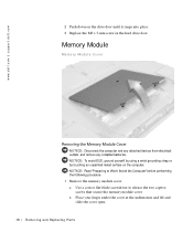
... batteries. NOTICE: Read "Preparing to Work Inside the Computer" before performing the following procedure. 1 Remove the memory module cover: a Use a coin or flat-blade screwdriver to release the two captive screws that secure the memory module cover. b Place your finger under the cover at the indentation and lift and slide the cover... touching an unpainted metal surface on the drive door until it snaps into place. 3 Replace the M3 x 5-mm screw in the hard drive door. www.dell.com | support.dell.com 2 Push down on the computer.
... batteries. NOTICE: Read "Preparing to Work Inside the Computer" before performing the following procedure. 1 Remove the memory module cover: a Use a coin or flat-blade screwdriver to release the two captive screws that secure the memory module cover. b Place your finger under the cover at the indentation and lift and slide the cover... touching an unpainted metal surface on the drive door until it snaps into place. 3 Replace the M3 x 5-mm screw in the hard drive door. www.dell.com | support.dell.com 2 Push down on the computer.
Service Manual
Page 19
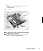
NOTICE: To avoid ESD, ground yourself by using a wrist grounding strap or by touching an unpainted metal surface on the computer. Memory Modules JDIM 1 JDIM 2 inner tabs (2 per socket) memory module sockets (2) Removing the Memory Modules NOTICE: Disconnect the computer and any attached devices from electrical outlets, and remove any installed batteries. Removing and Repl aci ng Part s 19 NOTE: The screw labeled with the "circle K" in the middle of the memory module cover secures the keyboard assembly and does not secure the memory module cover.
NOTICE: To avoid ESD, ground yourself by using a wrist grounding strap or by touching an unpainted metal surface on the computer. Memory Modules JDIM 1 JDIM 2 inner tabs (2 per socket) memory module sockets (2) Removing the Memory Modules NOTICE: Disconnect the computer and any attached devices from electrical outlets, and remove any installed batteries. Removing and Repl aci ng Part s 19 NOTE: The screw labeled with the "circle K" in the middle of the memory module cover secures the keyboard assembly and does not secure the memory module cover.
Service Manual
Page 20
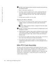
...two captive screws. NOTE: Memory modules are keyed, or designed to fit into place. With the module at a 45-degree angle to disengage from its socket. a wireless NIC must be connected to the wiring harness as appropriate; www.dell.com | support.dell.com NOTICE: Read "...Preparing to Work Inside the Computer" before the system board assembly can be inserted at a 45-degree angle, press the memory module's edge connector firmly into the bottom case assembly. ...
...two captive screws. NOTE: Memory modules are keyed, or designed to fit into place. With the module at a 45-degree angle to disengage from its socket. a wireless NIC must be connected to the wiring harness as appropriate; www.dell.com | support.dell.com NOTICE: Read "...Preparing to Work Inside the Computer" before the system board assembly can be inserted at a 45-degree angle, press the memory module's edge connector firmly into the bottom case assembly. ...
Service Manual
Page 22
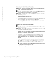
...they do not interfere with the socket at a 45-degree angle to Work Inside the Computer" before performing the following procedure. 1 Remove the memory module cover. 2 To release the mini-PCI card assembly from electrical outlets, and remove any attached cables. NOTE: A modem-only mini-...If you are installing a wireless NIC, fold and tuck the unused interface cables into its socket, in only one connector; www.dell.com | support.dell.com Removing the Mini-PCI Card Assembly NOTICE: Disconnect the computer and any attached devices from its socket and disconnect any installed batteries...
...they do not interfere with the socket at a 45-degree angle to Work Inside the Computer" before performing the following procedure. 1 Remove the memory module cover. 2 To release the mini-PCI card assembly from electrical outlets, and remove any attached cables. NOTE: A modem-only mini-...If you are installing a wireless NIC, fold and tuck the unused interface cables into its socket, in only one connector; www.dell.com | support.dell.com Removing the Mini-PCI Card Assembly NOTICE: Disconnect the computer and any attached devices from its socket and disconnect any installed batteries...
Service Manual
Page 50
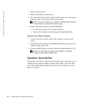
...left and right sides of the bottom case assembly. Speaker Assemblies The speakers are located on the EMI shield as shown in "Reserve Battery," contact Dell technical support. 4 Remove the reserve battery from the EMI shield: a Pry the reserve battery free from the foam pad. Replacing the Reserve Battery...is not located on the front left label. Take note of the foam pad from the EMI shield. www.dell.com | support.dell.com 1 Remove the hard drive. 2 Remove the memory module cover. 3 Disconnect the reserve battery cable from the connector on the EMI shield next to the connector to...
...left and right sides of the bottom case assembly. Speaker Assemblies The speakers are located on the EMI shield as shown in "Reserve Battery," contact Dell technical support. 4 Remove the reserve battery from the EMI shield: a Pry the reserve battery free from the foam pad. Replacing the Reserve Battery...is not located on the front left label. Take note of the foam pad from the EMI shield. www.dell.com | support.dell.com 1 Remove the hard drive. 2 Remove the memory module cover. 3 Disconnect the reserve battery cable from the connector on the EMI shield next to the connector to...
Service Manual
Page 56
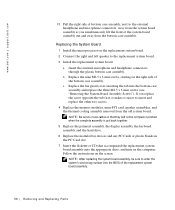
...Be sure to route cables so that they will not be sure to the replacement system board. 3 Install the replacement system board. www.dell.com | support.dell.com 13 Pull the right side of bottom case assembly, next to the external headphone and microphone connectors, away from the system board ...assembly as you replace the screw opposite the tab first, it makes it easier to insert and replace the other two screws. 4 Replace the memory modules,...
...Be sure to route cables so that they will not be sure to the replacement system board. 3 Install the replacement system board. www.dell.com | support.dell.com 13 Pull the right side of bottom case assembly, next to the external headphone and microphone connectors, away from the system board ...assembly as you replace the screw opposite the tab first, it makes it easier to insert and replace the other two screws. 4 Replace the memory modules,...
Service Manual
Page 59
... cable H hard drive, 17 removing, 17 replacing, 17 hinge covers removing, 39 replacing, 40 hybrid cooling fan removing, 46 K keyboard, 23 removing, 23 replacing, 25 M memory module, 18 removing, 19 replacing, 20 microprocessor module removing, 47 replacing, 48 microprocessor thermal cooling assembly removing, 44 mini-PCI card, 20 removing, 22 replacing...
... cable H hard drive, 17 removing, 17 replacing, 17 hinge covers removing, 39 replacing, 40 hybrid cooling fan removing, 46 K keyboard, 23 removing, 23 replacing, 25 M memory module, 18 removing, 19 replacing, 20 microprocessor module removing, 47 replacing, 48 microprocessor thermal cooling assembly removing, 44 mini-PCI card, 20 removing, 22 replacing...
System Information Guide
Page 6
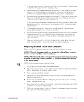
...removing PC Cards after turning off the computer before disconnecting a device or removing a memory module to help avoid the potential hazard of electric shock, do not connect or ...integrated or optional (PC Card) modem, the cable used batteries according to the manufacturers instructions or contact you are installing memory modules. NOTICE: The only time you should be manufactured with a minimum wire size of this product during normal operation... explode. connect the AC adapter from electrical outlets to the system board. support.dell.com Dell Latitude System Information 1-3
...removing PC Cards after turning off the computer before disconnecting a device or removing a memory module to help avoid the potential hazard of electric shock, do not connect or ...integrated or optional (PC Card) modem, the cable used batteries according to the manufacturers instructions or contact you are installing memory modules. NOTICE: The only time you should be manufactured with a minimum wire size of this product during normal operation... explode. connect the AC adapter from electrical outlets to the system board. support.dell.com Dell Latitude System Information 1-3
System Information Guide
Page 7
... memory module. You can do so by Dell could void your authority to comply with applicable regulations regarding your computer can harm electronic components inside your body before you touch any signal or emission, radiated in your online User's Guide. 1-4 Dell Latitude... System Information To prevent static damage, discharge static electricity from your computer. Additional regulatory information regarding EMI. For parallel printers, a cable is available from Dell Computer Corporation on the computer's I/O panel. •...
... memory module. You can do so by Dell could void your authority to comply with applicable regulations regarding your computer can harm electronic components inside your body before you touch any signal or emission, radiated in your online User's Guide. 1-4 Dell Latitude... System Information To prevent static damage, discharge static electricity from your computer. Additional regulatory information regarding EMI. For parallel printers, a cable is available from Dell Computer Corporation on the computer's I/O panel. •...
System Information Guide
Page 12
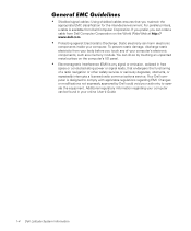
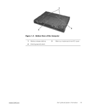
Bottom View of the Computer 1 Module release latches 2 Docking security latch 3 Memory module and mini-PCI cover support.dell.com Dell Latitude System Information 1-9 (Rev. 11/3/98) FILE LOCATION: D:\Eri_DProject\Dell\Temp\413CU0s\413CUeb0.fm Figure 1-5.
Bottom View of the Computer 1 Module release latches 2 Docking security latch 3 Memory module and mini-PCI cover support.dell.com Dell Latitude System Information 1-9 (Rev. 11/3/98) FILE LOCATION: D:\Eri_DProject\Dell\Temp\413CU0s\413CUeb0.fm Figure 1-5.


