Service Manual
Page 11
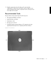
... in this manual require the following tools: • #1 magnetized Phillips screwdriver • Small flat-blade screwdriver • Small plastic scribe • Microprocessor extractor • Flash BIOS update program diskette or CD (required only when upgrading the microprocessor or replacing the reserve battery) System Orientation back left right front B e fo re You...
... in this manual require the following tools: • #1 magnetized Phillips screwdriver • Small flat-blade screwdriver • Small plastic scribe • Microprocessor extractor • Flash BIOS update program diskette or CD (required only when upgrading the microprocessor or replacing the reserve battery) System Orientation back left right front B e fo re You...
Service Manual
Page 49
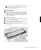
... the computer and any attached devices from electrical outlets, and remove any installed batteries. 3 Update the BIOS using a wrist grounding strap or by using a flash BIOS update program diskette or CD. Removing the battery causes the computer to the computer's RTC and NVRAM when...ESD, ground yourself by touching an unpainted metal surface on the computer. NOTICE: Read "Preparing to update or flash the BIOS, see the Dell Portable Computer BIOS Update Guide. Reserve Battery reserve battery reserve battery cable reserve battery connector Removing and Repl aci ng Part s 49 If ...
... the computer and any attached devices from electrical outlets, and remove any installed batteries. 3 Update the BIOS using a wrist grounding strap or by using a flash BIOS update program diskette or CD. Removing the battery causes the computer to the computer's RTC and NVRAM when...ESD, ground yourself by touching an unpainted metal surface on the computer. NOTICE: Read "Preparing to update or flash the BIOS, see the Dell Portable Computer BIOS Update Guide. Reserve Battery reserve battery reserve battery cable reserve battery connector Removing and Repl aci ng Part s 49 If ...
Service Manual
Page 50
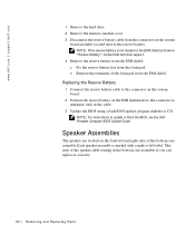
...flash BIOS update program diskette or CD. Take note of the bottom case assembly. Each speaker assembly is not located on the front left label. NOTE: If the reserve battery is marked with a right or left and right sides of the speaker cable routing in "Reserve Battery," contact Dell technical... the connector on the system board. 2 Position the reserve battery on the system board assembly located next to the reserve battery. www.dell.com | support.dell.com 1 Remove the hard drive. 2 Remove the memory module cover. 3 Disconnect the reserve battery cable from the connector on the ...
...flash BIOS update program diskette or CD. Take note of the bottom case assembly. Each speaker assembly is not located on the front left label. NOTE: If the reserve battery is marked with a right or left and right sides of the speaker cable routing in "Reserve Battery," contact Dell technical... the connector on the system board. 2 Position the reserve battery on the system board assembly located next to the reserve battery. www.dell.com | support.dell.com 1 Remove the hard drive. 2 Remove the memory module cover. 3 Disconnect the reserve battery cable from the connector on the ...
Service Manual
Page 53
.... Replacing the Speaker Assembly 1 To replace the speaker assembly, place the mounting ring over the front palmrest screw post. System Board Assembly The system board's BIOS chip contains the system's service tag number, which is longer than the right speaker. NOTICE: Do not pull the antenna cable when removing the speaker...
.... Replacing the Speaker Assembly 1 To replace the speaker assembly, place the mounting ring over the front palmrest screw post. System Board Assembly The system board's BIOS chip contains the system's service tag number, which is longer than the right speaker. NOTICE: Do not pull the antenna cable when removing the speaker...
Service Manual
Page 56
... bottom case assembly. NOTE: Be sure to route cables so that they will not be sure to enter the system's service tag number into the BIOS of the system board assembly out and away from the old system board. b Replace the nine M2.5 x 5-mm screws, starting on the screen. ... on the replacement system board. 2 Connect the right and left speaker to the replacement system board. 3 Install the replacement system board. www.dell.com | support.dell.com 13 Pull the right side of bottom case assembly, next to the external headphone and microphone connectors, away from the system board assembly...
... bottom case assembly. NOTE: Be sure to route cables so that they will not be sure to enter the system's service tag number into the BIOS of the system board assembly out and away from the old system board. b Replace the nine M2.5 x 5-mm screws, starting on the screen. ... on the replacement system board. 2 Connect the right and left speaker to the replacement system board. 3 Install the replacement system board. www.dell.com | support.dell.com 13 Pull the right side of bottom case assembly, next to the external headphone and microphone connectors, away from the system board assembly...


