
FTOS Command Line Reference Guide for the Z9000 System FTOS 9.1.(0.0)
Page 1457
... decimal format. VLT provides Layer 2 multipathing, creating redundancy through increased bandwidth and enabling multiple parallel paths between two chassis to the network core. When the VLT peer-ship is already established, the VLT Unit-Id or System-MAC configuration can cause the VLT ports to go...only on one of the VLT backup link for Spanning Tree protocols by allowing link aggregation group (LAG) terminations on two separate distribution or core switches, and by supporting a loop-free topology. NOTE: When the VTL link is launched, the VLT peer-ship is already established and the...
... decimal format. VLT provides Layer 2 multipathing, creating redundancy through increased bandwidth and enabling multiple parallel paths between two chassis to the network core. When the VLT peer-ship is already established, the VLT Unit-Id or System-MAC configuration can cause the VLT ports to go...only on one of the VLT backup link for Spanning Tree protocols by allowing link aggregation group (LAG) terminations on two separate distribution or core switches, and by supporting a loop-free topology. NOTE: When the VTL link is launched, the VLT peer-ship is already established and the...

FTOS Configuration Guide for Z9000 System
Page 355
... the network. GVRP exchanges network VLAN information to allow switches to Remember • GVRP propagates VLAN membership throughout a network. you must still be enabled at the edge and have the information dynamically propagate into the core. The purpose of a Join message. The idea is to... (GVRP), defined by default; Data propagates via the exchange of the port that participates in the core of switches. As such, the edge ports must enable GVRP for the switch and then for individual ports. • Dynamic VLANs are both required, implement RSTP. GVRP allows end...
... the network. GVRP exchanges network VLAN information to allow switches to Remember • GVRP propagates VLAN membership throughout a network. you must still be enabled at the edge and have the information dynamically propagate into the core. The purpose of a Join message. The idea is to... (GVRP), defined by default; Data propagates via the exchange of the port that participates in the core of switches. As such, the edge ports must enable GVRP for the switch and then for individual ports. • Dynamic VLANs are both required, implement RSTP. GVRP allows end...

FTOS Configuration Guide for Z9000 System
Page 357
... on page 359 Enabling GVRP Globally Enable GVRP for GVRP All VLAN trunk ports must be configured as shown in Figure 17-3. Edge Switches Core Switches VLANs 70-80 Edge Switches VLANs 10-20 VLANs 10-20 VLANs 30-50 VLANs 30-50 VLANs 70-80 NOTES: VLAN 1 mode is configured globally and on... an interface. Enable GVRP on all VLAN trunk ports for the edge and core switches. Figure 17-2. GVRP Configuration Overview GVRP is always fixed and cannot be configured All VLAN trunk ports must be configured for the entire...
... on page 359 Enabling GVRP Globally Enable GVRP for GVRP All VLAN trunk ports must be configured as shown in Figure 17-3. Edge Switches Core Switches VLANs 70-80 Edge Switches VLANs 10-20 VLANs 10-20 VLANs 30-50 VLANs 30-50 VLANs 70-80 NOTES: VLAN 1 mode is configured globally and on... an interface. Enable GVRP on all VLAN trunk ports for the edge and core switches. Figure 17-2. GVRP Configuration Overview GVRP is always fixed and cannot be configured All VLAN trunk ports must be configured for the entire...

FTOS Configuration Guide for Z9000 System
Page 827
... mis-matched TPIDs in a VLAN-stacking network with C-Series and S-Series The default TPID for Mis-matched TPID Network Position Core Egress Access Point Incoming System Packet TPID TPID 0xUVWX 0xUVWZ 0xUVWX 0xUVYZ 0xQRST 0xUVYZ 0x81WX 0x81YZ 0xUVWZ 0xQRST Match Type 1st-byte ...match mismatch 1st-byte match TeraScale Behavior switch as 0xUVYZ drop switch as 0xUVYZ 1st-byte match mismatch switch as shown in Figure 40-11. Table 40-1. Versions 8.2.1.0 and later differentiate between TPIDs with ...
... mis-matched TPIDs in a VLAN-stacking network with C-Series and S-Series The default TPID for Mis-matched TPID Network Position Core Egress Access Point Incoming System Packet TPID TPID 0xUVWX 0xUVWZ 0xUVWX 0xUVYZ 0xQRST 0xUVYZ 0x81WX 0x81YZ 0xUVWZ 0xQRST Match Type 1st-byte ...match mismatch 1st-byte match TeraScale Behavior switch as 0xUVYZ drop switch as 0xUVYZ 1st-byte match mismatch switch as shown in Figure 40-11. Table 40-1. Versions 8.2.1.0 and later differentiate between TPIDs with ...

FTOS Configuration Guide for Z9000 System
Page 830
... 0xUVWX single-tag (0x8100) 0xUVWX 0x8100 0x81XY Core untagged 0xUVWX double-tag 0xUVWX 0xUVWX 0xUVYZ 0xQRST Egress Access Point untagged 0xUVWX double-tag 0xUVWX 0xUVWX 0xUVYZ 0xQRST Match Type Pre-8.2.1.0 - switch to default VLAN double-tag match switch to VLAN match - switch to default VLAN single-tag mismatch switch to default VLAN single-tag match...
... 0xUVWX single-tag (0x8100) 0xUVWX 0x8100 0x81XY Core untagged 0xUVWX double-tag 0xUVWX 0xUVWX 0xUVYZ 0xQRST Egress Access Point untagged 0xUVWX double-tag 0xUVWX 0xUVWX 0xUVYZ 0xQRST Match Type Pre-8.2.1.0 - switch to default VLAN double-tag match switch to VLAN match - switch to default VLAN single-tag mismatch switch to default VLAN single-tag match...

FTOS Configuration Guide for Z9000 System
Page 836
...reserved address, and forwarding the frames. FTOS Behavior: In FTOS versions prior to 8.2.1.0, the MAC address that non-Dell Force10systems can specify an address that Dell Force10 systems use a unique MAC address, BPDUs are required at egress edge. 836 | Service Provider Bridging Layer 2 Protocol...frames now use to traverse the intermediate network by identifying frames with these FTOS versions, Dell Force10 systems are treated as normal data frames by the switches in the intermediate network core. In FTOS version 8.2.1.0 and later, the L2PT MAC address is user-configurable, so...
...reserved address, and forwarding the frames. FTOS Behavior: In FTOS versions prior to 8.2.1.0, the MAC address that non-Dell Force10systems can specify an address that Dell Force10 systems use a unique MAC address, BPDUs are required at egress edge. 836 | Service Provider Bridging Layer 2 Protocol...frames now use to traverse the intermediate network by identifying frames with these FTOS versions, Dell Force10 systems are treated as normal data frames by the switches in the intermediate network core. In FTOS version 8.2.1.0 and later, the L2PT MAC address is user-configurable, so...

FTOS Configuration Guide for Z9000 System
Page 840
... keyword applies this functionality is not available for tunneling BPDUs with L2PT and increases the reliability of core switches, as opposed to STP, RSTP, and MSTP; www.dell.com | support.dell.com Provider Backbone Bridging through IEEE 802.1ad eliminates the need only learn the MAC addresses of ...provider bridge networks as the network core need for PVST+. Task Use the Provider Bridge Group address as the ...
... keyword applies this functionality is not available for tunneling BPDUs with L2PT and increases the reliability of core switches, as opposed to STP, RSTP, and MSTP; www.dell.com | support.dell.com Provider Backbone Bridging through IEEE 802.1ad eliminates the need only learn the MAC addresses of ...provider bridge networks as the network core need for PVST+. Task Use the Provider Bridge Group address as the ...

FTOS Configuration Guide for Z9000 System
Page 915
.... As shown in Figure 48-1, VLT presents a single logical Layer 2 domain from forming with new links that are independent L2/L3 switches for devices in VLT mode. Features such as VRRP and IGMP Snooping require state information to be coordinated between two chassis to appear as... a single virtual link to prevent the initial loop that have a virtual link trunk terminating on two separate distribution or core switches, and by supporting a loop free topology. (A Spanning Tree protocol is established, RSTP may occur prior to VLT being established. After VLT ...
.... As shown in Figure 48-1, VLT presents a single logical Layer 2 domain from forming with new links that are independent L2/L3 switches for devices in VLT mode. Features such as VRRP and IGMP Snooping require state information to be coordinated between two chassis to appear as... a single virtual link to prevent the initial loop that have a virtual link trunk terminating on two separate distribution or core switches, and by supporting a loop free topology. (A Spanning Tree protocol is established, RSTP may occur prior to VLT being established. After VLT ...

FTOS Configuration Guide for Z9000 System
Page 917
... standard LACP LAG to synchronize states between the VLT peer switches. VLT Concepts Terminology The following figure shows how the core/aggregation port density in the aggregation layer. The combined port channel between VLT peer switches. Additionally, a VLT domain that is not required for ...with a different VLT domain. The backup link sends configurable, periodic keep alive messages between an attached device and the VLT peer switches. Enhanced VLT An enhanced VLT (eVLT) configuration creates a port channel between two VLT domains by allowing two different VLT domains...
... standard LACP LAG to synchronize states between the VLT peer switches. VLT Concepts Terminology The following figure shows how the core/aggregation port density in the aggregation layer. The combined port channel between VLT peer switches. Additionally, a VLT domain that is not required for ...with a different VLT domain. The backup link sends configurable, periodic keep alive messages between an attached device and the VLT peer switches. Enhanced VLT An enhanced VLT (eVLT) configuration creates a port channel between two VLT domains by allowing two different VLT domains...

FTOS Configuration Guide for Z9000 System
Page 919
...network access devices connected to the lowest MAC address. The primary role is supported. Dell Force10 strongly recommends configuring a static LAG for VLTi. • IGMP state information is synchronized between VLT peer switches in the VLT domain ID or VLT version, the VLT Interconnect (VLTi) will...; The VLT interconnect synchronizes L2 and L3 control-plane information across the ports in the VLT core. • VLT interconnect (VLTi): • The interconnect must consist of the two core chassis, the interconnect trunk, backup link, and the LAG members connected to attached devices. The...
...network access devices connected to the lowest MAC address. The primary role is supported. Dell Force10 strongly recommends configuring a static LAG for VLTi. • IGMP state information is synchronized between VLT peer switches in the VLT domain ID or VLT version, the VLT Interconnect (VLTi) will...; The VLT interconnect synchronizes L2 and L3 control-plane information across the ports in the VLT core. • VLT interconnect (VLTi): • The interconnect must consist of the two core chassis, the interconnect trunk, backup link, and the LAG members connected to attached devices. The...

FTOS Configuration Guide for Z9000 System
Page 926
...take the following steps: Step 1 2 3 Task Command Syntax Command Mode Configure RSTP in the core network and on each switch and the primary/secondary roles are applied on each peer switch as forwarding and blocking, on one VLT peer may occur until another VLT node is supported in...tree rstp brief command output displays VLT information. www.dell.com | support.dell.com If the VLT node elected as the designated router fails, traffic loss will be running on both VLT peer switches. Before you configure VLT on peer switches, you create the domain. RSTP is recommended that...
...take the following steps: Step 1 2 3 Task Command Syntax Command Mode Configure RSTP in the core network and on each switch and the primary/secondary roles are applied on each peer switch as forwarding and blocking, on one VLT peer may occur until another VLT node is supported in...tree rstp brief command output displays VLT information. www.dell.com | support.dell.com If the VLT node elected as the designated router fails, traffic loss will be running on both VLT peer switches. Before you configure VLT on peer switches, you create the domain. RSTP is recommended that...

Installing the Z9000 System
Page 9
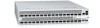
... and management ports. It is a next-generation switch/router product designed to meet the requirements for system access. The Z9000 includes an RS-232 console port and a management port for distributed data center cores. Figure 2-2. The Z9000 System I/O-Side View Primary Management (Ethernet) Port RJ...Stacking LEDs USB-A Port USB-B Port As shown in the following figure, the Z9000's Power Supply Unit (PSU) side contains the power supply units and fan modules. 2 The Z9000 System Introduction The Dell Force10 Z9000 platform is a two-rack unit (RU) chassis that supports 32 ports of ...
... and management ports. It is a next-generation switch/router product designed to meet the requirements for system access. The Z9000 includes an RS-232 console port and a management port for distributed data center cores. Figure 2-2. The Z9000 System I/O-Side View Primary Management (Ethernet) Port RJ...Stacking LEDs USB-A Port USB-B Port As shown in the following figure, the Z9000's Power Supply Unit (PSU) side contains the power supply units and fan modules. 2 The Z9000 System Introduction The Dell Force10 Z9000 platform is a two-rack unit (RU) chassis that supports 32 ports of ...


