
Installation Guide
Page 5
... servicing. WARNING: When no cable is required): http://www.dell.com/support/manuals. 5 Avoid exposure to a power source. 1 About this Guide This guide provides site preparation recommendations, and step-by-step procedures for access to some sections is connected,...transceiver ports. Related Publications For more information about the S5000, refer to the following documents: • FTOS Configuration Guide for the S5000 Switch • FTOS Command Line Reference Guide for the S5000 Switch • FTOS Release Notes for the S5000 Switch NOTE: For the most recent documentation and software...
... servicing. WARNING: When no cable is required): http://www.dell.com/support/manuals. 5 Avoid exposure to a power source. 1 About this Guide This guide provides site preparation recommendations, and step-by-step procedures for access to some sections is connected,...transceiver ports. Related Publications For more information about the S5000, refer to the following documents: • FTOS Configuration Guide for the S5000 Switch • FTOS Command Line Reference Guide for the S5000 Switch • FTOS Release Notes for the S5000 Switch NOTE: For the most recent documentation and software...

Installation Guide
Page 7
..., which is purpose-built to the FTOS Configuration Guide for flexible configuration. 7 The S5000 supports Data Center Bridging (ETS/PFC/DCBX), FCoE Transit (FIP Snooping), NPIV Proxy Gateway (NPG), and Internet small computer system interface (iSCSI) storage traffic. The S5000 is available on the Dell Support website at http://support.dell.com/manuals. It is part of...
..., which is purpose-built to the FTOS Configuration Guide for flexible configuration. 7 The S5000 supports Data Center Bridging (ETS/PFC/DCBX), FCoE Transit (FIP Snooping), NPIV Proxy Gateway (NPG), and Internet small computer system interface (iSCSI) storage traffic. The S5000 is available on the Dell Support website at http://support.dell.com/manuals. It is part of...

Installation Guide
Page 13
... The valid port numbers for each interface type are stack-unit numbers (from 0 to the FTOS Command Line Reference Guide and FTOS Configuration Guide for pluggable modules on the S5000 I/ O panel. As shown in several ways, including LEDs and through the CLI show commands and with simple network ...management protocol (SNMP). When the S5000 powers up or reloads, the status LED on the I/O and Utility side of the...
... The valid port numbers for each interface type are stack-unit numbers (from 0 to the FTOS Command Line Reference Guide and FTOS Configuration Guide for pluggable modules on the S5000 I/ O panel. As shown in several ways, including LEDs and through the CLI show commands and with simple network ...management protocol (SNMP). When the S5000 powers up or reloads, the status LED on the I/O and Utility side of the...
Installation Guide
Page 28
...slot. 3. Use the grab handle on one PSU for the S5000 Switch. The S5000 does not support mixing PSU types, that is, you must be sure to cover the second PSU slot opening with only one PSU, Dell Networking highly recommends using two PSUs for full redundancy and proper...power down the switch before removing and replacing an expansion module. 1. WARNING: The Utility panel consists of the FTOS Command Line Reference Guide for the S5000 Switch and FTOS Configuration Guide for a time, be the same. • For AC PSUs, an illuminated translucent handle indicates the power status. • To...
...slot. 3. Use the grab handle on one PSU for the S5000 Switch. The S5000 does not support mixing PSU types, that is, you must be sure to cover the second PSU slot opening with only one PSU, Dell Networking highly recommends using two PSUs for full redundancy and proper...power down the switch before removing and replacing an expansion module. 1. WARNING: The Utility panel consists of the FTOS Command Line Reference Guide for the S5000 Switch and FTOS Configuration Guide for a time, be the same. • For AC PSUs, an illuminated translucent handle indicates the power status. • To...

Installation Guide
Page 30
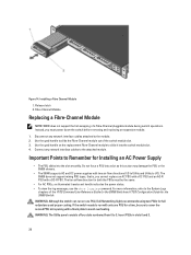
...electrical label and place it on the main regulatory label found on the AC system. NOTE: Ensure that the PSU is easily accessible. 4. The S5000 does not support mixing PSU types, that the socket-outlet is located/installed near the equipment and is correctly installed. AC3 Prong NOTE: The ... Figure 16. Ensure that is powered-up as soon as the main disconnect device on the bottom of the FTOS Command Line Reference Guide for the S5000 Switch and FTOS Configuration Guide for both the PSUs must be the same. • For DC PSUs, the power status LED is on the left corner. ...
...electrical label and place it on the main regulatory label found on the AC system. NOTE: Ensure that the PSU is easily accessible. 4. The S5000 does not support mixing PSU types, that the socket-outlet is located/installed near the equipment and is correctly installed. AC3 Prong NOTE: The ... Figure 16. Ensure that is powered-up as soon as the main disconnect device on the bottom of the FTOS Command Line Reference Guide for the S5000 Switch and FTOS Configuration Guide for both the PSUs must be the same. • For DC PSUs, the power status LED is on the left corner. ...

Installation Guide
Page 36
NOTE: For better performance, ensure that the system is connected to a stand-alone power source with only one PSU, Dell Networking highly recommends using two PSUs for full redundancy. Attach the power cord to maximum if the facility air condition fails or if a fan fails. ... with a minimum of 5 inches (12.7 cm) of four slots numbered from 0 to run on the right side of the FTOS Command Line Reference Guide for the S5000 Switch and FTOS Configuration Guide for a six-hour duration. • The cooling system is designed such that hot air is on the replacement PSU to I /O. There are...
NOTE: For better performance, ensure that the system is connected to a stand-alone power source with only one PSU, Dell Networking highly recommends using two PSUs for full redundancy. Attach the power cord to maximum if the facility air condition fails or if a fan fails. ... with a minimum of 5 inches (12.7 cm) of four slots numbered from 0 to run on the right side of the FTOS Command Line Reference Guide for the S5000 Switch and FTOS Configuration Guide for a six-hour duration. • The cooling system is designed such that hot air is on the replacement PSU to I /O. There are...

Installation Guide
Page 42
... the boot-up a new set of switches in the FTOS Command Line Reference Guide for the S5000 Switch. 42 The subsequent configuration file in the stack to each unit includes the awareness of the configuration file. Attaching a new unit may cause each unit in each AC power connector...that the configuration does not override the configuration of the management unit and unit IDs by the identification algorithm you should have a preconfigured unit that you want to add to the stack, but you add a unit to the Stacking chapter in the FTOS Configuration Guide for the S5000 Switch and...
... the boot-up a new set of switches in the FTOS Command Line Reference Guide for the S5000 Switch. 42 The subsequent configuration file in the stack to each unit includes the awareness of the configuration file. Attaching a new unit may cause each unit in each AC power connector...that the configuration does not override the configuration of the management unit and unit IDs by the identification algorithm you should have a preconfigured unit that you want to add to the stack, but you add a unit to the Stacking chapter in the FTOS Configuration Guide for the S5000 Switch and...

Getting Started Guide
Page 3
... configuration. WARNING: If any evidence of Rack (ToR) switches. For information about the S5000 switch, including how to the documents listed below: Table 1. The S5000 delivers Fibre Channel over Ethernet (FCoE) and Fibre Channel (FC) capability in the same box. Getting Started Guide This document is available on the Dell Support website at http://www.dell...
... configuration. WARNING: If any evidence of Rack (ToR) switches. For information about the S5000 switch, including how to the documents listed below: Table 1. The S5000 delivers Fibre Channel over Ethernet (FCoE) and Fibre Channel (FC) capability in the same box. Getting Started Guide This document is available on the Dell Support website at http://www.dell...

Getting Started Guide
Page 7
... slot numbers are solid green. 7 Figure 4. The valid port numbers for the S5000 Switch. For more information about these options, refer to the FTOS Command Line Reference Guide and FTOS Configuration Guide for each interface type are field replaceable. Fans The S5000 supports two fan trays with full redundancy (two PSUs installed and running), you...
... slot numbers are solid green. 7 Figure 4. The valid port numbers for the S5000 Switch. For more information about these options, refer to the FTOS Command Line Reference Guide and FTOS Configuration Guide for each interface type are field replaceable. Fans The S5000 supports two fan trays with full redundancy (two PSUs installed and running), you...

Getting Started Guide
Page 18
...Guide for the S5000 Switch and FTOS Configuration Guide for full redundancy and proper cooling. Release latch 2. Do not force a PSU into the slot smoothly. If the switch needs to run on one PSU for both the PSUs must be sure to cover the second PSU slot opening with only one PSU, Dell... Networking highly recommends using two PSUs for the S5000 Switch. WARNING: Electrostatic discharge (ESD) damage can run with a blank plate to 3. Fibre Channel Module Important Points to...
...Guide for the S5000 Switch and FTOS Configuration Guide for full redundancy and proper cooling. Release latch 2. Do not force a PSU into the slot smoothly. If the switch needs to run on one PSU for both the PSUs must be sure to cover the second PSU slot opening with only one PSU, Dell... Networking highly recommends using two PSUs for the S5000 Switch. WARNING: Electrostatic discharge (ESD) damage can run with a blank plate to 3. Fibre Channel Module Important Points to...

Getting Started Guide
Page 21
...Dell Networking highly recommends using two PSUs for Installing a DC Power Supply • When using DC power supply, peel off the DC electrical label and place it on the main regulatory label found on the bottom of the FTOS Command Line Reference Guide for the S5000 Switch and FTOS Configuration Guide ... The Utility panel consists of four slots numbered from 0 to the System Logs chapters of the S5000 chassis. Position this action may damage the PSU or the S5000 chassis. • The S5000 supports AC and DC power supplies with a blank plate to Remember for full redundancy and proper ...
...Dell Networking highly recommends using two PSUs for Installing a DC Power Supply • When using DC power supply, peel off the DC electrical label and place it on the main regulatory label found on the bottom of the FTOS Command Line Reference Guide for the S5000 Switch and FTOS Configuration Guide ... The Utility panel consists of four slots numbered from 0 to the System Logs chapters of the S5000 chassis. Position this action may damage the PSU or the S5000 chassis. • The S5000 supports AC and DC power supplies with a blank plate to Remember for full redundancy and proper ...

Getting Started Guide
Page 25
...and 75 percent of the shipping box. 2. The switch never intentionally turns off the fans. • For proper ventilation, position the S5000 in unit 0 The fan modules are field replaceable. CAUTION: DO NOT mix airflow directions. The airflow directions are listed in Technical Specifications.... slots numbered from the I /O). For more information, refer to the System Logs chapters of the FTOS Command Line Reference Guide for the S5000 Switch and FTOS Configuration Guide for Installing a Fan Module • The Utility panel consists of the chassis; Module slot 1 is designed such that...
...and 75 percent of the shipping box. 2. The switch never intentionally turns off the fans. • For proper ventilation, position the S5000 in unit 0 The fan modules are field replaceable. CAUTION: DO NOT mix airflow directions. The airflow directions are listed in Technical Specifications.... slots numbered from the I /O). For more information, refer to the System Logs chapters of the FTOS Command Line Reference Guide for the S5000 Switch and FTOS Configuration Guide for Installing a Fan Module • The Utility panel consists of the chassis; Module slot 1 is designed such that...

Getting Started Guide
Page 28
... about how to configure BMP, refer to FTOS Configuration Guide for both access ports. Assign interfaces to a terminal server. 2. Set the default terminal settings as the cable is connected between the S5000 and the power source, the chassis is no on the lower left-hand side of the S5000 as the console port. Configure layer 2 (data...
... about how to configure BMP, refer to FTOS Configuration Guide for both access ports. Assign interfaces to a terminal server. 2. Set the default terminal settings as the cable is connected between the S5000 and the power source, the chassis is no on the lower left-hand side of the S5000 as the console port. Configure layer 2 (data...

Getting Started Guide
Page 30
...automatically switches over the RJ-45 console by default. When you are connected to the FTOS Configuration Guide for the switch to access the S5000. 7. Enter the Initial Configuration Information To set up the switch, assign an IP address and other features and interfaces, ... the PC. 4. To configure other configuration information necessary for the S5000 Switch. Connect the USB-B end of cable into the USB-B console port on the PC. 2. USB-B Console Port Connector 1. For assistance, contact Dell Networking Technical Support. 3. The minimal configuration provided here does not cover...
...automatically switches over the RJ-45 console by default. When you are connected to the FTOS Configuration Guide for the switch to access the S5000. 7. Enter the Initial Configuration Information To set up the switch, assign an IP address and other features and interfaces, ... the PC. 4. To configure other configuration information necessary for the S5000 Switch. Connect the USB-B end of cable into the USB-B console port on the PC. 2. USB-B Console Port Connector 1. For assistance, contact Dell Networking Technical Support. 3. The minimal configuration provided here does not cover...


