
Owner's Manual
Page 1
Dell™ Dimension™ E521 Owner's Manual Service Tag CD or DVD eject button CD or DVD activity light FlexBay for optional floppy drive or Media Card Reader microphone connector headphone connector diagnostic lights hard-drive activity light power button/ power activity light USB 2.0 connectors (2) cover latch release Model DCSM www.dell.com | support.dell.com
Dell™ Dimension™ E521 Owner's Manual Service Tag CD or DVD eject button CD or DVD activity light FlexBay for optional floppy drive or Media Card Reader microphone connector headphone connector diagnostic lights hard-drive activity light power button/ power activity light USB 2.0 connectors (2) cover latch release Model DCSM www.dell.com | support.dell.com
Owner's Manual
Page 4
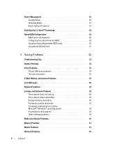
... Standby Mode 26 Hibernate Mode 27 Power Options Properties 27 Enabling Cool 'n' Quiet™ Technology 28 About RAID Configurations 29 RAID Level 1 Configuration 29 Configuring Your Hard Drives for RAID 30 Using ...
... Standby Mode 26 Hibernate Mode 27 Power Options Properties 27 Enabling Cool 'n' Quiet™ Technology 28 About RAID Configurations 29 RAID Level 1 Configuration 29 Configuring Your Hard Drives for RAID 30 Using ...

Owner's Manual
Page 5
Power Problems 43 Printer Problems 44 Scanner Problems 45 Sound and Speaker Problems 46 No sound from speakers 46 No sound from headphones 47 Video and Monitor Problems 47 If the screen is blank 47 If the screen is difficult to read 48 3 Troubleshooting Tools 49 Diagnostic Lights 49 Dell Diagnostics 52 Dell...Drivers 54 Resolving Software and Hardware Incompatibilities 55 Restoring Your Operating System 55 Using Microsoft Windows XP System Restore 56 Using Dell PC Restore 57 Using the Operating System CD 59 4 Removing and Installing Parts 61 Before You Begin 61 Recommended ...
Power Problems 43 Printer Problems 44 Scanner Problems 45 Sound and Speaker Problems 46 No sound from speakers 46 No sound from headphones 47 Video and Monitor Problems 47 If the screen is blank 47 If the screen is difficult to read 48 3 Troubleshooting Tools 49 Diagnostic Lights 49 Dell Diagnostics 52 Dell...Drivers 54 Resolving Software and Hardware Incompatibilities 55 Restoring Your Operating System 55 Using Microsoft Windows XP System Restore 56 Using Dell PC Restore 57 Using the Operating System CD 59 4 Removing and Installing Parts 61 Before You Begin 61 Recommended ...
Owner's Manual
Page 12
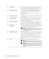
...computer is on the diagnostic code. 5 FlexBay drive 6 microphone connector 7 headphone connector 8 diagnostic lights (4) 9 hard-drive activity light 10 power button, power light 11 USB 2.0 connectors (2) 12 vents Can contain an optional floppy drive or optional Media Card Reader. Use the lights to help you ...use the power button to the computer. 12 Setting Up and Using Your Computer Use the front USB connectors for voice or musical input into ...
...computer is on the diagnostic code. 5 FlexBay drive 6 microphone connector 7 headphone connector 8 diagnostic lights (4) 9 hard-drive activity light 10 power button, power light 11 USB 2.0 connectors (2) 12 vents Can contain an optional floppy drive or optional Media Card Reader. Use the lights to help you ...use the power button to the computer. 12 Setting Up and Using Your Computer Use the front USB connectors for voice or musical input into ...
Owner's Manual
Page 13
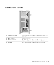
See "Back Panel Connectors" on page 14 for any installed PCI and PCI Express cards. Setting Up and Using Your Computer 13 Access connectors for more information. Back View of the Computer 1 2 3 1 voltage selection switch 2 power connector 3 back panel connectors 4 card slots 4 See the safety instructions in the Product Information Guide for more information. Plug USB, audio, and other devices into the appropriate connector. Insert the power cable.
See "Back Panel Connectors" on page 14 for any installed PCI and PCI Express cards. Setting Up and Using Your Computer 13 Access connectors for more information. Back View of the Computer 1 2 3 1 voltage selection switch 2 power connector 3 back panel connectors 4 card slots 4 See the safety instructions in the Product Information Guide for more information. Plug USB, audio, and other devices into the appropriate connector. Insert the power cable.

Owner's Manual
Page 26
... to automatically activate after a time-out. When a Windows XP Professional computer is on the screen. Standby Mode Standby mode conserves power by . To immediately activate standby mode without a period of inactivity, click the Start button, click Turn Off Computer, and then... button and click Control Panel. 2 Under Pick a category, click Performance and Maintenance. 3 Under or pick a Control Panel icon, click Power Options. NOTE: Selecting the connection method This computer connects directly to the Internet enables the integrated firewall provided with Windows XP Service Pack. 4...
... to automatically activate after a time-out. When a Windows XP Professional computer is on the screen. Standby Mode Standby mode conserves power by . To immediately activate standby mode without a period of inactivity, click the Start button, click Turn Off Computer, and then... button and click Control Panel. 2 Under Pick a category, click Performance and Maintenance. 3 Under or pick a Control Panel icon, click Power Options. NOTE: Selecting the connection method This computer connects directly to the Internet enables the integrated firewall provided with Windows XP Service Pack. 4...

Owner's Manual
Page 27
... • Max Battery - Power Options Properties Define your computer, choose a scheme from batteries for extended periods of the standard Windows schemes installed on the keyboard or moving the mouse does not bring the computer out of the computer memory, Dell creates an appropriately sized hibernate mode... file before it was in the fields below the scheme name. The Power schemes drop-down menu. Pressing a key on your standby mode settings, hibernate ...
... • Max Battery - Power Options Properties Define your computer, choose a scheme from batteries for extended periods of the standard Windows schemes installed on the keyboard or moving the mouse does not bring the computer out of the computer memory, Dell creates an appropriately sized hibernate mode... file before it was in the fields below the scheme name. The Power schemes drop-down menu. Pressing a key on your standby mode settings, hibernate ...

Owner's Manual
Page 28
... problem, always set the hard drive (hard disk) to time-out before the computer exits from standby mode or hibernate mode. • Program the power button to activate standby mode, activate hibernate mode, or turn off hard disks, System stand by, or System hibernates field, and then select a time...-out from the corresponding drop-down menu in the Windows taskbar for quick access. • Set the computer to prompt you defined on the Power Schemes tab, click the Enable hibernate support check box on the keyboard or click the mouse. To program these functions, click an option from ...
... problem, always set the hard drive (hard disk) to time-out before the computer exits from standby mode or hibernate mode. • Program the power button to activate standby mode, activate hibernate mode, or turn off hard disks, System stand by, or System hibernates field, and then select a time...-out from the corresponding drop-down menu in the Windows taskbar for quick access. • Set the computer to prompt you defined on the Power Schemes tab, click the Enable hibernate support check box on the keyboard or click the mouse. To program these functions, click an option from ...
Owner's Manual
Page 35
... DISC - 1 Click the Start button and click Control Panel. 2 Under Pick a category, click Performance and Maintenance. 3 Under or pick a Control Panel icon, click Power Options. 4 From the Power Schemes tab, select Always On. If you write to a digital telephone network. E-Mail, Modem, and Internet Problems CAUTION: Before you begin any of bad...
... DISC - 1 Click the Start button and click Control Panel. 2 Under Pick a category, click Performance and Maintenance. 3 Under or pick a Control Panel icon, click Power Options. 4 From the Power Schemes tab, select Always On. If you write to a digital telephone network. E-Mail, Modem, and Internet Problems CAUTION: Before you begin any of bad...

Owner's Manual
Page 38
... for at least 8 to get a response by pressing a key on page 55. Connect a properly working keyboard to perform an operating system shutdown. ENSURE THAT THE POWER CABLE IS FIRMLY CONNECTED TO THE COMPUTER AND TO THE ELECTRICAL OUTLET The computer stops responding NOTICE: You might lose data if you are unable...
... for at least 8 to get a response by pressing a key on page 55. Connect a properly working keyboard to perform an operating system shutdown. ENSURE THAT THE POWER CABLE IS FIRMLY CONNECTED TO THE COMPUTER AND TO THE ELECTRICAL OUTLET The computer stops responding NOTICE: You might lose data if you are unable...
Owner's Manual
Page 39
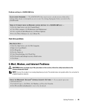
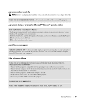
... THE SOFTWARE MANUFACTURER FOR TROUBLESHOOTING INFORMATION - • Ensure that the program is installed and configured properly. • Verify that your mouse, press and hold the power button for an earlier Microsoft® Windows® operating system RUN THE PROGRAM COMPATIBILITY WIZARD - If you are unable to All Programs→ Accessories, and...
... THE SOFTWARE MANUFACTURER FOR TROUBLESHOOTING INFORMATION - • Ensure that the program is installed and configured properly. • Verify that your mouse, press and hold the power button for an earlier Microsoft® Windows® operating system RUN THE PROGRAM COMPATIBILITY WIZARD - If you are unable to All Programs→ Accessories, and...

Owner's Manual
Page 43
... P O W E R L I G H T I S S T E A D Y A M B E R - The computer is either turned off or is not receiving power. • Reseat the power cable into both the power connector on the back of the procedures in this section, follow the safety instructions in standby mode. I F T H E P O W E R L I G H T I... S O F F - A device might be malfunctioning or incorrectly installed. • Ensure that the power strip is in the Product Information Guide. C H E C K Y O U R N E T W O R K S E T T I N G G R E E N - See "...
... P O W E R L I G H T I S S T E A D Y A M B E R - The computer is either turned off or is not receiving power. • Reseat the power cable into both the power connector on the back of the procedures in this section, follow the safety instructions in standby mode. I F T H E P O W E R L I G H T I... S O F F - A device might be malfunctioning or incorrectly installed. • Ensure that the power strip is in the Product Information Guide. C H E C K Y O U R N E T W O R K S E T T I N G G R E E N - See "...

Owner's Manual
Page 44
... H E P R I N T E R D O C U M E N T A T I N T E R F E R E N C E - TE S T T H E E L E C T R I N G A M B E R - The computer is receiving electrical power, but an internal power problem might exist. • Ensure that the printer cables are : • Power, keyboard, and mouse extension cables • Too many devices on page 13. • Ensure that the electrical outlet... Components" on page 15). See "Back View of the Computer" on a power strip • Multiple power strips connected to match the AC power at your printer, contact the printer's manufacturer. NOTE: If you begin any...
... H E P R I N T E R D O C U M E N T A T I N T E R F E R E N C E - TE S T T H E E L E C T R I N G A M B E R - The computer is receiving electrical power, but an internal power problem might exist. • Ensure that the printer cables are : • Power, keyboard, and mouse extension cables • Too many devices on page 13. • Ensure that the electrical outlet... Components" on page 15). See "Back View of the Computer" on a power strip • Multiple power strips connected to match the AC power at your printer, contact the printer's manufacturer. NOTE: If you begin any...

Owner's Manual
Page 47
... turned on the setup diagram for troubleshooting procedures. TE S T T H E E L E C T R I G H T S - See "Diagnostic Lights" on page 11). NOTE: See the monitor documentation for your screen. If the power light is off, firmly press the button to have missing pins.) C H E C K T H E M O N I T O R P O W E R L I N D O W S V O L U M E C O N T ...not muted. Click or double-click the speaker icon in the Product Information Guide. Ensure that the sound is lit or blinking, the monitor has power. A D J U S T T H E W I G H T - Video and Monitor Problems CAUTION: Before you are using a ...
... turned on the setup diagram for troubleshooting procedures. TE S T T H E E L E C T R I G H T S - See "Diagnostic Lights" on page 11). NOTE: See the monitor documentation for your screen. If the power light is off, firmly press the button to have missing pins.) C H E C K T H E M O N I T O R P O W E R L I N D O W S V O L U M E C O N T ...not muted. Click or double-click the speaker icon in the Product Information Guide. Ensure that the sound is lit or blinking, the monitor has power. A D J U S T T H E W I G H T - Video and Monitor Problems CAUTION: Before you are using a ...
Owner's Manual
Page 49
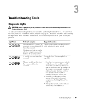
... processor failure has Contact Dell (see "Installing Memory"...has four lights labeled "1," "2," "3," and "4" on the front panel (see "Contacting Dell" on page 11). If the computer starts normally, reinstall an additional module. When ...memory modules installed, remove the modules, reinstall one module (see "Contacting Dell" on page 68), and then restart the computer. Troubleshooting Tools Diagnostic Lights... computer (see "Installing Memory" on page 68). • If the problem persists, contact Dell (see "Front View of the Computer" on page 122). To help you have identified a...
... processor failure has Contact Dell (see "Installing Memory"...has four lights labeled "1," "2," "3," and "4" on the front panel (see "Contacting Dell" on page 11). If the computer starts normally, reinstall an additional module. When ...memory modules installed, remove the modules, reinstall one module (see "Contacting Dell" on page 68), and then restart the computer. Troubleshooting Tools Diagnostic Lights... computer (see "Installing Memory" on page 68). • If the problem persists, contact Dell (see "Front View of the Computer" on page 122). To help you have identified a...

Owner's Manual
Page 50
A possible floppy or hard drive failure has occurred. Reinstall all power and data cables and restart the computer. Suggested Resolution • If the computer has a graphics card, remove the card, reinstall it (see "PCI Express Cards" ... available, install properly working memory of the same type into your computer (see "Installing Memory" on page 68). • If the problem persists, contact Dell (see "Contacting Dell" on page 122). • Ensure that you are installing are detected. Light Pattern Problem Description A possible graphics card failure has occurred. No memory modules...
A possible floppy or hard drive failure has occurred. Reinstall all power and data cables and restart the computer. Suggested Resolution • If the computer has a graphics card, remove the card, reinstall it (see "PCI Express Cards" ... available, install properly working memory of the same type into your computer (see "Installing Memory" on page 68). • If the problem persists, contact Dell (see "Contacting Dell" on page 122). • Ensure that you are installing are detected. Light Pattern Problem Description A possible graphics card failure has occurred. No memory modules...

Owner's Manual
Page 61
...A component can be replaced or-if purchased separately-installed by performing the removal procedure in your operating system, press and hold the power button for removing and installing the components in reverse order. b In the Turn off computer window, click Turn off after the ...Ensure that the following tools: • Small flat-blade screwdriver • Phillips screwdriver • Flash BIOS executable update program on support.dell.com. Removing and Installing Parts 61 If your computer and attached devices did not automatically turn off your computer. 1 Shut down your ...
...A component can be replaced or-if purchased separately-installed by performing the removal procedure in your operating system, press and hold the power button for removing and installing the components in reverse order. b In the Turn off computer window, click Turn off after the ...Ensure that the following tools: • Small flat-blade screwdriver • Phillips screwdriver • Flash BIOS executable update program on support.dell.com. Removing and Installing Parts 61 If your computer and attached devices did not automatically turn off your computer. 1 Shut down your ...

Owner's Manual
Page 62
... and all attached devices from potential damage and to help protect your computer from their electrical outlets, and then press the power button to servicing that is not authorized by Dell is not covered by your computer and then unplug it from the network device. 2 Disconnect any static electricity that both connectors...
... and all attached devices from potential damage and to help protect your computer from their electrical outlets, and then press the power button to servicing that is not authorized by Dell is not covered by your computer and then unplug it from the network device. 2 Disconnect any static electricity that both connectors...

Owner's Manual
Page 64
4 Grip the sides of the procedures in this section, follow the safety instructions in a secure location. Inside View of Your Computer CAUTION: Before you begin any of the computer cover and pivot the cover up, using the bottom hinge tabs as leverage points. 5 Release the cover from the hinge tabs and set it aside in the Product Information Guide. 3 4 2 *1 *May not be present on all computers. 1 floppy drive or Media Reader 4 system board 2 CD or DVD drive 5 hard drive 5 3 power supply 64 Removing and Installing Parts
4 Grip the sides of the procedures in this section, follow the safety instructions in a secure location. Inside View of Your Computer CAUTION: Before you begin any of the computer cover and pivot the cover up, using the bottom hinge tabs as leverage points. 5 Release the cover from the hinge tabs and set it aside in the Product Information Guide. 3 4 2 *1 *May not be present on all computers. 1 floppy drive or Media Reader 4 system board 2 CD or DVD drive 5 hard drive 5 3 power supply 64 Removing and Installing Parts
Owner's Manual
Page 65
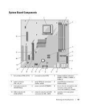
... 6 7 20 8 19 18 9 17 16 15 14 13 12 11 10 1 fan connector (FAN_CPU1) 2 processor socket (CPU) 4 power connector (PW_12V_A1) 7 front-panel connector (FRONTPANEL) 10 USB connectors (2) (USB2_BACK1) 5 serial ATA drive connectors (SATA2, SATA3) 8 power connector (POWER1) 11 network connector and USB connectors (2) (NIC_USB1) 3 memory module connectors (DIMM_1, DIMM_2, DIMM_3, DIMM_4) 6 serial...
... 6 7 20 8 19 18 9 17 16 15 14 13 12 11 10 1 fan connector (FAN_CPU1) 2 processor socket (CPU) 4 power connector (PW_12V_A1) 7 front-panel connector (FRONTPANEL) 10 USB connectors (2) (USB2_BACK1) 5 serial ATA drive connectors (SATA2, SATA3) 8 power connector (POWER1) 11 network connector and USB connectors (2) (NIC_USB1) 3 memory module connectors (DIMM_1, DIMM_2, DIMM_3, DIMM_4) 6 serial...


