Owner's Manual
Page 5
...Reinstalling Drivers 55 Restoring Your Operating System 56 Using Microsoft Windows XP System Restore 56 Using Dell PC Restore by Symantec 57 Resolving Software and Hardware Incompatibilities 58 4 Removing and Installing Parts Before You Begin 59 Recommended Tools 59 Turning Off Your Computer 59 Before... Working Inside Your Computer 60 Front View 61 Back View 63 Front-Panel Door and Hinge Arms 65 Reattaching the Hinge...
...Reinstalling Drivers 55 Restoring Your Operating System 56 Using Microsoft Windows XP System Restore 56 Using Dell PC Restore by Symantec 57 Resolving Software and Hardware Incompatibilities 58 4 Removing and Installing Parts Before You Begin 59 Recommended Tools 59 Turning Off Your Computer 59 Before... Working Inside Your Computer 60 Front View 61 Back View 63 Front-Panel Door and Hinge Arms 65 Reattaching the Hinge...
Owner's Manual
Page 6
... General Installation Guidelines 89 Connecting Drive Cables 89 Hard Drive 90 Removing a Hard Drive 91 Installing a Hard Drive 92 Adding a Second Hard Drive 93 Front-Panel Inserts 94 Floppy Drive 97 Removing a Floppy Drive 97 Installing a Floppy Drive 98 CD/DVD Drive 99 Removing a CD/DVD Drive 100 Installing a CD/DVD Drive 101 Battery...
... General Installation Guidelines 89 Connecting Drive Cables 89 Hard Drive 90 Removing a Hard Drive 91 Installing a Hard Drive 92 Adding a Second Hard Drive 93 Front-Panel Inserts 94 Floppy Drive 97 Removing a Floppy Drive 97 Installing a Floppy Drive 98 CD/DVD Drive 99 Removing a CD/DVD Drive 100 Installing a CD/DVD Drive 101 Battery...
Owner's Manual
Page 19
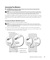
... VGA (blue) connector Setting Up and Using Your Computer 19 If you begin any of them must have VGA connectors, you are connecting two flat-panel monitors, at least one monitor (VGA or DVI) in addition to the TV. If you must have a VGA connector. If you are connecting two ... you may connect only one of the procedures in this section, follow these instructions to connect and enable your computer has integrated video, do not remove the cap to connect the monitor or the monitor will not function. 2 Connect one monitor with a VGA connector and one of the monitors to the...
... VGA (blue) connector Setting Up and Using Your Computer 19 If you begin any of them must have VGA connectors, you are connecting two flat-panel monitors, at least one monitor (VGA or DVI) in addition to the TV. If you must have a VGA connector. If you are connecting two ... you may connect only one of the procedures in this section, follow these instructions to connect and enable your computer has integrated video, do not remove the cap to connect the monitor or the monitor will not function. 2 Connect one monitor with a VGA connector and one of the monitors to the...
Owner's Manual
Page 36
If Work Offline has a checkmark next to it, click the checkmark to remove it and connect to All Programs, and then click Modem Helper. www.dell.com | support.dell.com CHECK THE TELEPHONE LINE CONNECTION - CONNECT THE MODEM DIRECTLY TO THE TELEPHONE WALL JACK - Error Messages CAUTION: ...e-mail program open, click File. If all computers.) VERIFY THAT THE MODEM IS COMMUNICATING WITH WINDOWS - 1 Click the Start button and click Control Panel. 2 Click Printers and Other Hardware. 3 Click Phone and Modem Options. 4 Click the Modems tab. 5 Click the COM port for your Internet ...
If Work Offline has a checkmark next to it, click the checkmark to remove it and connect to All Programs, and then click Modem Helper. www.dell.com | support.dell.com CHECK THE TELEPHONE LINE CONNECTION - CONNECT THE MODEM DIRECTLY TO THE TELEPHONE WALL JACK - Error Messages CAUTION: ...e-mail program open, click File. If all computers.) VERIFY THAT THE MODEM IS COMMUNICATING WITH WINDOWS - 1 Click the Start button and click Control Panel. 2 Click Printers and Other Hardware. 3 Click Phone and Modem Options. 4 Click the Modems tab. 5 Click the COM port for your Internet ...
Owner's Manual
Page 37
...missing an essential file. To remove and then reinstall the program: 1 Click the Start button, click Control Panel, and then click Add or Remove Programs. 2 Select the ... 1394 DEVICE IS RECOGNIZED BY WINDOWS - 1 Click the Start button and click Control Panel. 2 Click Printers and Other Hardware. Insert a bootable floppy disk or CD. S YS T E M D I N G S YS T E M N O T F O U N D - Contact Dell (see page 123). D L L F I S N O T R E A D Y - T H E D E V I C E I L E W A S N O T F O U N D - The drive cannot read the disk. N O T E N O U G H M E M O R Y O R R E S O U R C E S . C L...
...missing an essential file. To remove and then reinstall the program: 1 Click the Start button, click Control Panel, and then click Add or Remove Programs. 2 Select the ... 1394 DEVICE IS RECOGNIZED BY WINDOWS - 1 Click the Start button and click Control Panel. 2 Click Printers and Other Hardware. Insert a bootable floppy disk or CD. S YS T E M D I N G S YS T E M N O T F O U N D - Contact Dell (see page 123). D L L F I S N O T R E A D Y - T H E D E V I C E I L E W A S N O T F O U N D - The drive cannot read the disk. N O T E N O U G H M E M O R Y O R R E S O U R C E S . C L...
Owner's Manual
Page 41
...bent or broken pins and for instructions on page 107. • Run the Dell Diagnostics (see page 73). • Your computer supports DDR2 memory. C L E A N T H E M O U S E - See page 119 for damaged or frayed cables. TE S T T H E M O U S E - Straighten bent pins. 2 Remove mouse extension cables, if used, and connect the mouse directly to the computer...memory supported by your computer, see "Memory" on cleaning the mouse. CHECK THE MOUSE SETTINGS - 1 Click the Start button, click Control Panel, and then click Printers and Other Hardware. 2 Click Mouse. 3 Try adjusting the settings.
...bent or broken pins and for instructions on page 107. • Run the Dell Diagnostics (see page 73). • Your computer supports DDR2 memory. C L E A N T H E M O U S E - See page 119 for damaged or frayed cables. TE S T T H E M O U S E - Straighten bent pins. 2 Remove mouse extension cables, if used, and connect the mouse directly to the computer...memory supported by your computer, see "Memory" on cleaning the mouse. CHECK THE MOUSE SETTINGS - 1 Click the Start button, click Control Panel, and then click Printers and Other Hardware. 2 Click Mouse. 3 Try adjusting the settings.

Owner's Manual
Page 43
... power strip is plugged into an electrical outlet and that the main power cable and front panel cable are : • Power, keyboard, and mouse extension cables • Too many ... strips, and power extension cables to the system board (see page 71). A device might exist. NOTE: If you begin any cards (see page 76). • Remove and then reinstall the graphics card, if applicable (see page 71). See the printer documentation for your location (if applicable). I F T H E P O W E R L I G H T I S B L I N K I O N - E L I M I N A T E I S S T E A D Y A M B E R - I F T H E P O W ...
... power strip is plugged into an electrical outlet and that the main power cable and front panel cable are : • Power, keyboard, and mouse extension cables • Too many ... strips, and power extension cables to the system board (see page 71). A device might exist. NOTE: If you begin any cards (see page 76). • Remove and then reinstall the graphics card, if applicable (see page 71). See the printer documentation for your location (if applicable). I F T H E P O W E R L I G H T I S B L I N K I O N - E L I M I N A T E I S S T E A D Y A M B E R - I F T H E P O W ...
Owner's Manual
Page 62
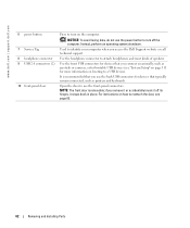
www.dell.com | support.dell.com 6 power button 7 Service Tag 8 headphone connector 9 USB 2.0 connectors (2) 10 front-panel door Press to attach headphones and most kinds of speakers. Used to identify your computer when you remove it or accidentally knock it off the computer. It is removable; NOTE: The ...To avoid losing data, do not use the front-panel connectors. Use the front USB connectors for devices that typically remain connected, such as joysticks or cameras, or for bootable USB devices (see page 65. 62 Removing and Installing Parts Open the door to reattach the ...
www.dell.com | support.dell.com 6 power button 7 Service Tag 8 headphone connector 9 USB 2.0 connectors (2) 10 front-panel door Press to attach headphones and most kinds of speakers. Used to identify your computer when you remove it or accidentally knock it off the computer. It is removable; NOTE: The ...To avoid losing data, do not use the front-panel connectors. Use the front USB connectors for devices that typically remain connected, such as joysticks or cameras, or for bootable USB devices (see page 65. 62 Removing and Installing Parts Open the door to reattach the ...
Owner's Manual
Page 65
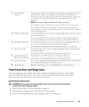
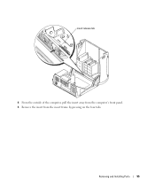
... and connectors for devices that typically remain connected, such as printers and keyboards. If the front-panel door is open and it into the network connector. NOTE: Do not plug a telephone cable ... your network. A click indicates that you have a USB keyboard, plug it off the two hinge arms. Removing and Installing Parts 65 On computers with integrated amplifiers. It is recommended that you use the connector on the ... 2 Disconnect the computer power cable from the electrical outlet. 3 Remove the front-panel door by gently snapping it into a sound or telephony program.
... and connectors for devices that typically remain connected, such as printers and keyboards. If the front-panel door is open and it into the network connector. NOTE: Do not plug a telephone cable ... your network. A click indicates that you have a USB keyboard, plug it off the two hinge arms. Removing and Installing Parts 65 On computers with integrated amplifiers. It is recommended that you use the connector on the ... 2 Disconnect the computer power cable from the electrical outlet. 3 Remove the front-panel door by gently snapping it into a sound or telephony program.
Owner's Manual
Page 66
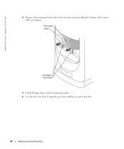
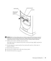
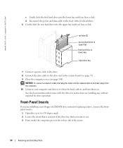
front-panel insert use fingers to pull here 5 Lift both hinge arms to the horizontal position. 6 Use the two view slots to align the pivot bar with your fingers. www.dell.com | support.dell.com 4 Remove the front-panel insert above the door bay area by pulling the bottom of the insert with the two pivot-bar slots. 66 Removing and Installing Parts
front-panel insert use fingers to pull here 5 Lift both hinge arms to the horizontal position. 6 Use the two view slots to align the pivot bar with your fingers. www.dell.com | support.dell.com 4 Remove the front-panel insert above the door bay area by pulling the bottom of the insert with the two pivot-bar slots. 66 Removing and Installing Parts
Owner's Manual
Page 67
Removing and Installing Parts 67 If the hinge arms do not snap back into position on the first attempt, slightly reposition the arms and try again. 8 ... into position. While you until they snap into position, lower and raise the arms two or three times to properly seat them. 9 Reattach the front-panel insert. 10 Reconnect the computer power cable to dissipate any static electricity that could harm internal components. 7 Pull the arms toward you work, periodically touch...
Removing and Installing Parts 67 If the hinge arms do not snap back into position on the first attempt, slightly reposition the arms and try again. 8 ... into position. While you until they snap into position, lower and raise the arms two or three times to properly seat them. 9 Reattach the front-panel insert. 10 Reconnect the computer power cable to dissipate any static electricity that could harm internal components. 7 Pull the arms toward you work, periodically touch...
Owner's Manual
Page 71
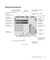
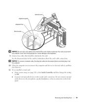
... (PASS) processor and heat-sink connector processor power connector (12V PWR) back of computer hard-drive activity light for add-in cards (SCSI LED) front-panel connector (FRONT PANEL) internal speaker (SPKR) card fan connector (PCI FAN) clear CMOS jumper (CLR CMOS) battery socket (BATTERY) PCI Express x16 card connector front...
... (PASS) processor and heat-sink connector processor power connector (12V PWR) back of computer hard-drive activity light for add-in cards (SCSI LED) front-panel connector (FRONT PANEL) internal speaker (SPKR) card fan connector (PCI FAN) clear CMOS jumper (CLR CMOS) battery socket (BATTERY) PCI Express x16 card connector front...
Owner's Manual
Page 79
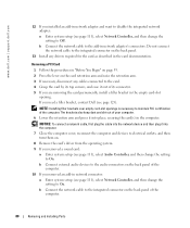
b Connect external audio devices to electrical outlets, and then turn them on the back panel. Removing and Installing Parts 79 alignment guide alignment bar filler bracket retention arm NOTICE: Do not route card cables over the cards can prevent the computer ...
b Connect external audio devices to electrical outlets, and then turn them on the back panel. Removing and Installing Parts 79 alignment guide alignment bar filler bracket retention arm NOTICE: Do not route card cables over the cards can prevent the computer ...
Owner's Manual
Page 80
...computer. 7 Close the computer cover, reconnect the computer and devices to electrical outlets, and then turn them on. 8 Remove the card's driver from the operating system. 9 If you removed an add-in network connector: a Enter system setup (see page 111), select Network Controller, and then change the ...cable to the add-in the computer. Do not connect the network cable to the integrated connector on the back panel of its connector. 5 If you need a filler bracket, contact Dell (see page 111), select Audio Controller, and then change the setting to On. b Connect external audio devices...
...computer. 7 Close the computer cover, reconnect the computer and devices to electrical outlets, and then turn them on. 8 Remove the card's driver from the operating system. 9 If you removed an add-in network connector: a Enter system setup (see page 111), select Network Controller, and then change the ...cable to the add-in the computer. Do not connect the network cable to the integrated connector on the back panel of its connector. 5 If you need a filler bracket, contact Dell (see page 111), select Audio Controller, and then change the setting to On. b Connect external audio devices...
Owner's Manual
Page 85
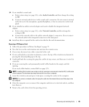
... a filler bracket, contact Dell (see page 123). If you installed a sound card: a Enter system setup (see page 111), select Network Controller, and then change the setting to the microphone, speaker/headphone, or line-in connectors on the back panel. 15 If you are removing the card permanently, install ... and then change the setting to maintain FCC certification of your card includes a retention mechanism, remove the top of the retention mechanism by pressing the tab and pulling up on the back panel. 16 Install any cables connected to the card. 4 If your computer. 7 Lower the ...
... a filler bracket, contact Dell (see page 123). If you installed a sound card: a Enter system setup (see page 111), select Network Controller, and then change the setting to the microphone, speaker/headphone, or line-in connectors on the back panel. 15 If you are removing the card permanently, install ... and then change the setting to maintain FCC certification of your card includes a retention mechanism, remove the top of the retention mechanism by pressing the tab and pulling up on the back panel. 16 Install any cables connected to the card. 4 If your computer. 7 Lower the ...
Owner's Manual
Page 86
... Parts If a card fan is not present in your computer. b Connect external audio devices to the audio connectors on the back panel of the computer. 11 If you removed an add-in the card documentation. b Connect the network cable to the integrated connector on the inside of the computer. 12 Install...111), select Audio Controller, and then change the setting to On. Card Fan NOTICE: PCI Express graphics card that runs at 75 W or higher, contact Dell (see page 123) to find out how to purchase a card fan. CAUTION: Before you begin any of the procedures in this section, follow the ...
... Parts If a card fan is not present in your computer. b Connect external audio devices to the audio connectors on the back panel of the computer. 11 If you removed an add-in the card documentation. b Connect the network cable to the integrated connector on the inside of the computer. 12 Install...111), select Audio Controller, and then change the setting to On. Card Fan NOTICE: PCI Express graphics card that runs at 75 W or higher, contact Dell (see page 123) to find out how to purchase a card fan. CAUTION: Before you begin any of the procedures in this section, follow the ...
Owner's Manual
Page 94
...documentation that you are installing a new floppy or CD/DVD drive instead of replacing a drive, remove the frontpanel inserts. 1 Open the cover to a 90-degree angle. 2 Locate the insert ... drive. 6 Gently slide the new hard drive into the upper bay until you hear a click. www.dell.com | support.dell.com c Gently slide the first hard drive into the lower bay until you hear a click. rail tabs.... 10 Connect your computer and devices to the back of the insert. 94 Removing and Installing Parts Front-Panel Inserts If you want to the system board (see page 71). 9 Close the computer cover (...
...documentation that you are installing a new floppy or CD/DVD drive instead of replacing a drive, remove the frontpanel inserts. 1 Open the cover to a 90-degree angle. 2 Locate the insert ... drive. 6 Gently slide the new hard drive into the upper bay until you hear a click. www.dell.com | support.dell.com c Gently slide the first hard drive into the lower bay until you hear a click. rail tabs.... 10 Connect your computer and devices to the back of the insert. 94 Removing and Installing Parts Front-Panel Inserts If you want to the system board (see page 71). 9 Close the computer cover (...
Owner's Manual
Page 95
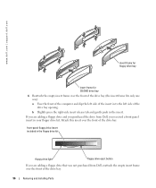
insert release tab 4 From the outside of the computer, pull the insert away from the computer's front panel. 5 Remove the insert from the insert frame by pressing on the four tabs. Removing and Installing Parts 95
insert release tab 4 From the outside of the computer, pull the insert away from the computer's front panel. 5 Remove the insert from the insert frame by pressing on the four tabs. Removing and Installing Parts 95
Owner's Manual
Page 96
... drive insert included in the floppy drive kit floppy drive light floppy drive eject button If you received a front panel insert in your floppy drive kit. www.dell.com | support.dell.com insert frame for floppy drive bay insert frame for CD/DVD drive bay 6 Reattach the empty insert frame over the ... tab and gently push in the insert. If you are adding a floppy drive and you purchased the drive from Dell, you are adding a floppy drive that was not purchased from Dell, reattach the empty insert frame over the front of the drive bay opening. Attach this insert over the front of...
... drive insert included in the floppy drive kit floppy drive light floppy drive eject button If you received a front panel insert in your floppy drive kit. www.dell.com | support.dell.com insert frame for floppy drive bay insert frame for CD/DVD drive bay 6 Reattach the empty insert frame over the ... tab and gently push in the insert. If you are adding a floppy drive and you purchased the drive from Dell, you are adding a floppy drive that was not purchased from Dell, reattach the empty insert frame over the front of the drive bay opening. Attach this insert over the front of...
Owner's Manual
Page 99
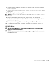
CD/DVD Drive CAUTION: Before you are installing a new floppy drive rather than replacing a drive, remove the front-panel inserts (see page 94). 6 Check all cable connections, and fold cables out of the procedures in this section, follow the safety instructions located .... 8 Connect your computer from the electrical outlet before opening the cover. See the documentation that your computer works correctly by running the Dell Diagnostics (see page 52). Removing and Installing Parts 99 NOTICE: To connect a network cable, first plug the cable in to the network device and then plug it ...
CD/DVD Drive CAUTION: Before you are installing a new floppy drive rather than replacing a drive, remove the front-panel inserts (see page 94). 6 Check all cable connections, and fold cables out of the procedures in this section, follow the safety instructions located .... 8 Connect your computer from the electrical outlet before opening the cover. See the documentation that your computer works correctly by running the Dell Diagnostics (see page 52). Removing and Installing Parts 99 NOTICE: To connect a network cable, first plug the cable in to the network device and then plug it ...


