Owner's Manual
Page 4
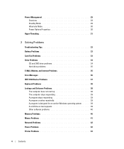
... responding 39 A program crashes repeatedly 39 A program is designed for an earlier Windows operating system. . . . . 39 A solid blue screen appears 39 Other software problems 40 Memory Problems 40 Mouse Problems 41 Network Problems 42 Power Problems 42 Printer Problems 43 4 Contents
... responding 39 A program crashes repeatedly 39 A program is designed for an earlier Windows operating system. . . . . 39 A solid blue screen appears 39 Other software problems 40 Memory Problems 40 Mouse Problems 41 Network Problems 42 Power Problems 42 Printer Problems 43 4 Contents
Owner's Manual
Page 6
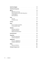
Inside Your Computer 70 System Board Components 71 Memory 72 DDR2 Memory Overview 72 Addressing Memory With 4-GB Configurations 73 Installing Memory 73 Removing Memory 75 Cards 75 PCI Cards 76 PCI Express Cards 81 Card Fan 86 Drives 89 General Installation Guidelines 89 Connecting Drive Cables 89 Hard Drive ...
Inside Your Computer 70 System Board Components 71 Memory 72 DDR2 Memory Overview 72 Addressing Memory With 4-GB Configurations 73 Installing Memory 73 Removing Memory 75 Cards 75 PCI Cards 76 PCI Express Cards 81 Card Fan 86 Drives 89 General Installation Guidelines 89 Connecting Drive Cables 89 Hard Drive ...
Owner's Manual
Page 10
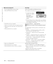
...• Documentation for devices (such as memory, the hard drive, and the operating system • Customer Care - Dell Support Website - Online discussion with other Dell customers • Upgrades - Drivers, patches, and software updates • Reference - The Dell Support website provides several online tools, including:... • Solutions - Contact information, order status, warranty, and repair information • Downloads - www.dell.com | support.dell.com What Are You Looking For? • Service Tag and Express Service Code • Microsoft Windows License Label ...
...• Documentation for devices (such as memory, the hard drive, and the operating system • Customer Care - Dell Support Website - Online discussion with other Dell customers • Upgrades - Drivers, patches, and software updates • Reference - The Dell Support website provides several online tools, including:... • Solutions - Contact information, order status, warranty, and repair information • Downloads - www.dell.com | support.dell.com What Are You Looking For? • Service Tag and Express Service Code • Microsoft Windows License Label ...
Owner's Manual
Page 17
...or DVDs. NOTE: The types of the window, and then click RecordNow Help or RecordNow Tutorial. The DVD-writable drives installed in Dell™ computers can also use Sonic RecordNow for available software patches at the Sonic support website at support.sonic.com. However, DVD-...writable drives do not write to computers that have copyright protection and cannot be copied using too much memory and preventing DVD playback, adjust the display properties. 1 Click the Start button and click Control Panel. 2 Under Pick a category, click Appearance ...
...or DVDs. NOTE: The types of the window, and then click RecordNow Help or RecordNow Tutorial. The DVD-writable drives installed in Dell™ computers can also use Sonic RecordNow for available software patches at the Sonic support website at support.sonic.com. However, DVD-...writable drives do not write to computers that have copyright protection and cannot be copied using too much memory and preventing DVD playback, adjust the display properties. 1 Click the Start button and click Control Panel. 2 Under Pick a category, click Appearance ...
Owner's Manual
Page 30
... Maintenance. 3 Under or pick a Control Panel icon, click Power Options. 4 Define your computer, choose a scheme from hibernate mode. www.dell.com | support.dell.com Hibernate Mode Hibernate mode conserves power by copying system data to a reserved area on the hard drive and then completely turning off the...keyboard and the mouse do not function when the computer is a portable computer that you want to select one of the computer memory, Dell creates an appropriately sized hibernate mode file before it was in the fields below the scheme name. Each scheme has different settings for...
... Maintenance. 3 Under or pick a Control Panel icon, click Power Options. 4 Define your computer, choose a scheme from hibernate mode. www.dell.com | support.dell.com Hibernate Mode Hibernate mode conserves power by copying system data to a reserved area on the hard drive and then completely turning off the...keyboard and the mouse do not function when the computer is a portable computer that you want to select one of the computer memory, Dell creates an appropriately sized hibernate mode file before it was in the fields below the scheme name. Each scheme has different settings for...
Owner's Manual
Page 40
...THE SOFTWARE DOCUMENTATION OR CONTACT THE SOFTWARE MANUFACTURER FOR TROUBLESHOOTING INFORMATION - • Ensure that the program is compatible with the memory. • Run the Dell Diagnostics (see if that resolves the problem. • See the software documentation for information. • Ensure that the program... the minimum hardware requirements needed to see page 52). 40 Solving Problems See the software documentation for minimum memory requirements. IF YOU RECEIVE AN INSUFFICIENT MEMORY MESSAGE - • Save and close any open files and exit any open programs you begin any of...
...THE SOFTWARE DOCUMENTATION OR CONTACT THE SOFTWARE MANUFACTURER FOR TROUBLESHOOTING INFORMATION - • Ensure that the program is compatible with the memory. • Run the Dell Diagnostics (see if that resolves the problem. • See the software documentation for information. • Ensure that the program... the minimum hardware requirements needed to see page 52). 40 Solving Problems See the software documentation for minimum memory requirements. IF YOU RECEIVE AN INSUFFICIENT MEMORY MESSAGE - • Save and close any open files and exit any open programs you begin any of...
Owner's Manual
Page 41
...Memory" on the setup diagram for your computer, and then restart the computer. Connect a properly working mouse to the computer. 3 Shut down or Turn Off, and then press . 3 After the computer turns off, reconnect the mouse cable as shown on page 107. • Run the Dell... S E - TE S T T H E M O U S E - IF YOU EXPERIENCE OTHER MEMORY PROBLEMS - • Reseat the memory modules (see page 73) to ensure that your computer is successfully communicating with the memory. • Ensure that you begin any of memory supported by your computer, see page 73). • Your computer supports DDR2...
...Memory" on the setup diagram for your computer, and then restart the computer. Connect a properly working mouse to the computer. 3 Shut down or Turn Off, and then press . 3 After the computer turns off, reconnect the mouse cable as shown on page 107. • Run the Dell... S E - TE S T T H E M O U S E - IF YOU EXPERIENCE OTHER MEMORY PROBLEMS - • Reseat the memory modules (see page 73) to ensure that your computer is successfully communicating with the memory. • Ensure that you begin any of memory supported by your computer, see page 73). • Your computer supports DDR2...

Owner's Manual
Page 43
... the processor power cable is receiving electrical power, but an internal power problem might be malfunctioning or incorrectly installed. • Remove and then reinstall the memory modules (see page 71). The computer is securely connected to the same electrical outlet Printer Problems CAUTION: Before you need technical assistance for setup and...
... the processor power cable is receiving electrical power, but an internal power problem might be malfunctioning or incorrectly installed. • Remove and then reinstall the memory modules (see page 71). The computer is securely connected to the same electrical outlet Printer Problems CAUTION: Before you need technical assistance for setup and...
Owner's Manual
Page 50
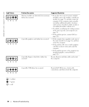
...and then restart the computer. = yellow = green = off 50 Advanced Troubleshooting www.dell.com | support.dell.com Light Pattern ABCD ABCD ABCD Problem Description Suggested Resolution Memory modules are detected, but a memory failure has occurred. • If you have identified a faulty module or reinstalled all... modules without error. • If available, install properly working memory of the same type into your computer (see page 73). • If the problem persists, contact Dell (see page 123). A possible floppy or hard drive failure has occurred. A...
...and then restart the computer. = yellow = green = off 50 Advanced Troubleshooting www.dell.com | support.dell.com Light Pattern ABCD ABCD ABCD Problem Description Suggested Resolution Memory modules are detected, but a memory failure has occurred. • If you have identified a faulty module or reinstalled all... modules without error. • If available, install properly working memory of the same type into your computer (see page 73). • If the problem persists, contact Dell (see page 123). A possible floppy or hard drive failure has occurred. A...
Owner's Manual
Page 51
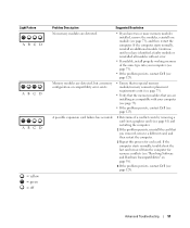
... you have identified a faulty module or reinstalled all modules without error. • If available, install properly working memory of the same type into your computer (see page 73). • If the problem persists, contact Dell (see page 123). If the computer starts normally, reinstall an additional module. Continue until you removed, remove...
... you have identified a faulty module or reinstalled all modules without error. • If available, install properly working memory of the same type into your computer (see page 73). • If the problem persists, contact Dell (see page 123). If the computer starts normally, reinstall an additional module. Continue until you removed, remove...
Owner's Manual
Page 54
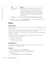
..., click Performance and Maintenance. 3 Click System. 4 In the System Properties window, click the Hardware tab. 54 Advanced Troubleshooting The Dell Diagnostics obtains configuration information for all devices attached to install drivers if you experience a problem with your hardware configuration for the selected device.... The device list may need to your computer or all devices from system setup, memory, and various internal tests, and it displays the information in the device list in the left pane of your problem and...
..., click Performance and Maintenance. 3 Click System. 4 In the System Properties window, click the Hardware tab. 54 Advanced Troubleshooting The Dell Diagnostics obtains configuration information for all devices attached to install drivers if you experience a problem with your hardware configuration for the selected device.... The device list may need to your computer or all devices from system setup, memory, and various internal tests, and it displays the information in the device list in the left pane of your problem and...
Owner's Manual
Page 71
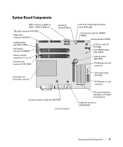
... Board Components SATA connectors (SATA-O, SATA-1, SATA-2, SATA-3) IDE drive connector (PRI IDE) floppy drive connector (FLOPPY) standby power light (AUX_PWR) main power connector (POWER) memory module connectors (1, 2, 3, 4) processor fan connector (CPU FAN) password jumper (PASS) processor and heat-sink connector processor power connector (12V PWR) back of computer hard-drive...
... Board Components SATA connectors (SATA-O, SATA-1, SATA-2, SATA-3) IDE drive connector (PRI IDE) floppy drive connector (FLOPPY) standby power light (AUX_PWR) main power connector (POWER) memory module connectors (1, 2, 3, 4) processor fan connector (CPU FAN) password jumper (PASS) processor and heat-sink connector processor power connector (12V PWR) back of computer hard-drive...
Owner's Manual
Page 72
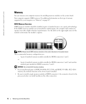
... connector 1, the connector closest to operate, but with a slight reduction in the other connectors. 72 Removing and Installing Parts A pair of matched memory size, speed, and technology. Your computer supports DDR2 memory. See the label on the system board. www.dell.com | support.dell.com Memory You can increase your computer, see "Memory" on page 107.
... connector 1, the connector closest to operate, but with a slight reduction in the other connectors. 72 Removing and Installing Parts A pair of matched memory size, speed, and technology. Your computer supports DDR2 memory. See the label on the system board. www.dell.com | support.dell.com Memory You can increase your computer, see "Memory" on page 107.
Owner's Manual
Page 73
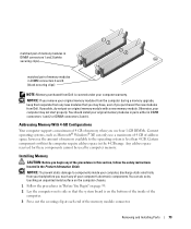
... before you may not start properly. Removing and Installing Parts 73 matched pair of memory modules in DIMM connectors 1 and 2 (white securing clips) matched pair of memory modules in DIMM connectors 3 and 4 (black securing clips) NOTE: Memory purchased from Dell is less than 4 GB. You can only use a maximum of 4 GB of the procedures...
... before you may not start properly. Removing and Installing Parts 73 matched pair of memory modules in DIMM connectors 1 and 2 (white securing clips) matched pair of memory modules in DIMM connectors 3 and 4 (black securing clips) NOTE: Memory purchased from Dell is less than 4 GB. You can only use a maximum of 4 GB of the procedures...
Owner's Manual
Page 74
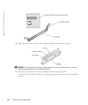
www.dell.com | support.dell.com memory connector closest to processor securing clips (2) connector 4 Align the notch on the bottom of the module. 5 Insert the module into the connector until the module snaps into position. notch memory module cutouts (2) crossbar NOTICE: To avoid damage to each end of the module. 74 Removing... Installing Parts If you insert the module correctly, the securing clips snap into the connector while you apply equal force to the memory module, press the module straight down into the cutouts at each end of the module with the crossbar in the connector.
www.dell.com | support.dell.com memory connector closest to processor securing clips (2) connector 4 Align the notch on the bottom of the module. 5 Insert the module into the connector until the module snaps into position. notch memory module cutouts (2) crossbar NOTICE: To avoid damage to each end of the module. 74 Removing... Installing Parts If you insert the module correctly, the securing clips snap into the connector while you apply equal force to the memory module, press the module straight down into the cutouts at each end of the module with the crossbar in the connector.
Owner's Manual
Page 75
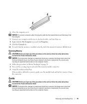
... Begin" on . 8 Right-click the My Computer icon and click Properties. 9 Click the General tab. 10 To verify that the memory is difficult to remove, gently ease the module back and forth to components inside your computer's electronic components. NOTICE: To prevent static damage..., check the amount of the procedures in this section, follow the safety instructions located in the Product Information Guide. Removing Memory CAUTION: Before you touch any of memory (RAM) listed. NOTICE: To connect a network cable, first plug the cable into the computer. 7 Connect your computer...
... Begin" on . 8 Right-click the My Computer icon and click Properties. 9 Click the General tab. 10 To verify that the memory is difficult to remove, gently ease the module back and forth to components inside your computer's electronic components. NOTICE: To prevent static damage..., check the amount of the procedures in this section, follow the safety instructions located in the Product Information Guide. Removing Memory CAUTION: Before you touch any of memory (RAM) listed. NOTICE: To connect a network cable, first plug the cable into the computer. 7 Connect your computer...
Owner's Manual
Page 107
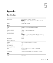
...MHz DDR2 unbuffered SDRAM four 256 MB, 512 MB, or 1 GB, non-ECC 256 MB 4 GB NOTE: See "Addressing Memory With 4-GB Configurations" on your processor) PCI Express Appendix 107 or 1066-MHz data rate (depending on page 73 to the ... Intel 925XE Express eight 24 4-Mb Integrated network interface capable of memory available to verify the amount of 10/100/1000 communication. 800- Appendix Specifications Processor Processor type Cache Memory Type Memory connectors Memory capacities Minimum memory Maximum memory BIOS address Computer Information Chipset DMA channels Interrupt levels BIOS chip (...
...MHz DDR2 unbuffered SDRAM four 256 MB, 512 MB, or 1 GB, non-ECC 256 MB 4 GB NOTE: See "Addressing Memory With 4-GB Configurations" on your processor) PCI Express Appendix 107 or 1066-MHz data rate (depending on page 73 to the ... Intel 925XE Express eight 24 4-Mb Integrated network interface capable of memory available to verify the amount of 10/100/1000 communication. 800- Appendix Specifications Processor Processor type Cache Memory Type Memory connectors Memory capacities Minimum memory Maximum memory BIOS address Computer Information Chipset DMA channels Interrupt levels BIOS chip (...
Owner's Manual
Page 109
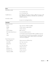
... 2.3 PCI Express x1 PCI Express x16 Telephony (TAPI) two 3.5-inch drive bays two 5.25-inch drive bays Serial ATA drive, floppy drive, Zip drive, USB memory devices, CD drive, CD-RW drive, DVD drive, DVD-RW drive, and DVD and CD-RW combo drive two bays for 1-inch high hard drives...
... 2.3 PCI Express x1 PCI Express x16 Telephony (TAPI) two 3.5-inch drive bays two 5.25-inch drive bays Serial ATA drive, floppy drive, Zip drive, USB memory devices, CD drive, CD-RW drive, DVD drive, DVD-RW drive, and DVD and CD-RW combo drive two bays for 1-inch high hard drives...
Owner's Manual
Page 111
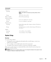
...: Unless you are an expert computer user, do not change a user-selectable option such as the user password • To read the current amount of memory or set or change the settings for future reference. Environmental Temperature: Operating Storage Relative humidity Maximum vibration: Operating Storage Maximum shock: Operating Storage Altitude: Operating...
...: Unless you are an expert computer user, do not change a user-selectable option such as the user password • To read the current amount of memory or set or change the settings for future reference. Environmental Temperature: Operating Storage Relative humidity Maximum vibration: Operating Storage Maximum shock: Operating Storage Altitude: Operating...
Owner's Manual
Page 113
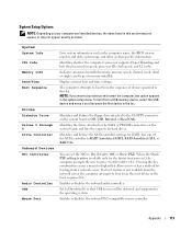
.... When the On w/ PXE setting is not available from the network server, the computer attempts to boot from the sequence of memory installed. Pressing this list. Enables or disables the onboard PS/2-compatible mouse controller. Identifies whether the computer's processor supports Hyper-Threading ... boot device and restart the computer, this section may not appear, or may not appear exactly as listed. Indicates amount of installed memory, memory speed, channel mode (dual or single), and type of devices specified in this key combination causes a menu to display that USB devices...
.... When the On w/ PXE setting is not available from the network server, the computer attempts to boot from the sequence of memory installed. Pressing this list. Enables or disables the onboard PS/2-compatible mouse controller. Identifies whether the computer's processor supports Hyper-Threading ... boot device and restart the computer, this section may not appear, or may not appear exactly as listed. Indicates amount of installed memory, memory speed, channel mode (dual or single), and type of devices specified in this key combination causes a menu to display that USB devices...


