
Owner's Manual
Page 26
...processors, capable of Hyper-Threading technology. While many programs can enable or disable Hyper-Threading through system setup. Contact the software manufacturer for Hyper-Threading and may require an update from the software manufacturer. To determine if your software. For more information on the Dell... Manager window, click the plus (+) sign next to take advantage of performing certain tasks simultaneously. If Hyper-Threading is enabled, the processor is an Intel® technology that you use the Microsoft® Windows® XP Service Pack 1 (SP1) or later operating ...
...processors, capable of Hyper-Threading technology. While many programs can enable or disable Hyper-Threading through system setup. Contact the software manufacturer for Hyper-Threading and may require an update from the software manufacturer. To determine if your software. For more information on the Dell... Manager window, click the plus (+) sign next to take advantage of performing certain tasks simultaneously. If Hyper-Threading is enabled, the processor is an Intel® technology that you use the Microsoft® Windows® XP Service Pack 1 (SP1) or later operating ...
Owner's Manual
Page 37
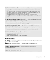
... installed. • Remove and then reinstall the memory modules (see page 61). E L I M I N A T E I O N - C H E C K T H E P R I N T E R D O C U M E N T A T I N T E R F E R E N C E - See the printer documentation for your location (if applicable). • Ensure that the processor power cable is working by testing it with another device, such as a lamp. • Ensure that the power strip is turned on a power strip •...
... installed. • Remove and then reinstall the memory modules (see page 61). E L I M I N A T E I O N - C H E C K T H E P R I N T E R D O C U M E N T A T I N T E R F E R E N C E - See the printer documentation for your location (if applicable). • Ensure that the processor power cable is working by testing it with another device, such as a lamp. • Ensure that the power strip is turned on a power strip •...

Owner's Manual
Page 43
... "D" on condition and the operating system is running. • The computer is in a normal off condition. • None. • If the computer is off . A possible processor failure has occurred. When the computer starts normally, all four lights go off , plug it into a working electrical outlet and press the power button. After...
... "D" on condition and the operating system is running. • The computer is in a normal off condition. • None. • If the computer is off . A possible processor failure has occurred. When the computer starts normally, all four lights go off , plug it into a working electrical outlet and press the power button. After...

Owner's Manual
Page 54
...and Installing Parts CAUTION: To guard against electrical shock, always unplug your computer from potential damage and to ground the system board. www.dell.com | support.dell.com Before Working Inside Your Computer Use the following steps before removing the cover. 4 Remove the computer cover (see page 53). ...your computer (see page 59). CAUTION: Before you begin working inside your computer, ground yourself by touching an unpainted metal surface, such as a processor by its edges, not by your computer. NOTICE: When you begin any static electricity that is not authorized by...
...and Installing Parts CAUTION: To guard against electrical shock, always unplug your computer from potential damage and to ground the system board. www.dell.com | support.dell.com Before Working Inside Your Computer Use the following steps before removing the cover. 4 Remove the computer cover (see page 53). ...your computer (see page 59). CAUTION: Before you begin working inside your computer, ground yourself by touching an unpainted metal surface, such as a processor by its edges, not by your computer. NOTICE: When you begin any static electricity that is not authorized by...
Owner's Manual
Page 61
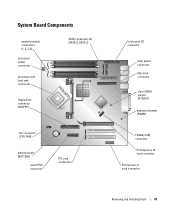
System Board Components memory module connectors (1, 2, 3, 4) processor power connector processor and heat sink connector SATA connectors (2) (SATA-0, SATA-2) floppy drive connector (FLOPPY) fan connector (CPU FAN) battery socket (BATTERY) serial PS/2 connector PCI card connectors front panel I/O connector main power connector IDE drive connector clear CMOS jumper (RTCRST) password jumper (PSWD) FlexBay USB connector PCI Express x16 card connector PCI Express x1 card connector Removing and Installing Parts 61
System Board Components memory module connectors (1, 2, 3, 4) processor power connector processor and heat sink connector SATA connectors (2) (SATA-0, SATA-2) floppy drive connector (FLOPPY) fan connector (CPU FAN) battery socket (BATTERY) serial PS/2 connector PCI card connectors front panel I/O connector main power connector IDE drive connector clear CMOS jumper (RTCRST) password jumper (PSWD) FlexBay USB connector PCI Express x16 card connector PCI Express x1 card connector Removing and Installing Parts 61

Owner's Manual
Page 62
www.dell.com | support.dell.com Memory You can increase your computer, see "Memory" on page 101. A pair of matched memory modules installed in DIMM connectors 1 and 2 and another matched ... a single memory module in the order indicated on the system board. NOTE: Always install DDR2 memory modules in DIMM connector 1, the connector closest to the processor, before you install mixed pairs of memory supported by your computer memory by installing memory modules on the system board. A pair of matched memory size...
www.dell.com | support.dell.com Memory You can increase your computer, see "Memory" on page 101. A pair of matched memory modules installed in DIMM connectors 1 and 2 and another matched ... a single memory module in the order indicated on the system board. NOTE: Always install DDR2 memory modules in DIMM connector 1, the connector closest to the processor, before you install mixed pairs of memory supported by your computer memory by installing memory modules on the system board. A pair of matched memory size...

Owner's Manual
Page 64
www.dell.com | support.dell.com 3 Press out the securing clip at each end of the module with the crossbar in the connector. notch memory module cutouts (2) crossbar NOTICE: To ... the module straight down into the connector while you insert the module correctly, the securing clips snap into position. If you apply equal force to processor securing clips (2) connector 4 Align the notch on the bottom of the module. 64 Removing and Installing Parts memory connector closest to each end of the...
www.dell.com | support.dell.com 3 Press out the securing clip at each end of the module with the crossbar in the connector. notch memory module cutouts (2) crossbar NOTICE: To ... the module straight down into the connector while you insert the module correctly, the securing clips snap into position. If you apply equal force to processor securing clips (2) connector 4 Align the notch on the bottom of the module. 64 Removing and Installing Parts memory connector closest to each end of the...

Owner's Manual
Page 101
..."Addressing Memory With 4-GB Configurations" on your computer configuration) pipelined-burst, eight-way set associative, write-back SRAM 400- Appendix Specifications Processor Processor type Level 1 (L1) cache Level 2 (L2) cache Memory Type Memory connectors Memory capacities Minimum memory Maximum memory BIOS address Computer ...levels BIOS chip (NVRAM) NIC System clock Intel® Pentium® 4 with Hyper-Threading technology NOTE: Not all Pentium 4 processors support Hyper-Threading technology. 16 KB 1 MB (depending on page 63 to verify the amount of 10/100 communication 800-MHz ...
..."Addressing Memory With 4-GB Configurations" on your computer configuration) pipelined-burst, eight-way set associative, write-back SRAM 400- Appendix Specifications Processor Processor type Level 1 (L1) cache Level 2 (L2) cache Memory Type Memory connectors Memory capacities Minimum memory Maximum memory BIOS address Computer ...levels BIOS chip (NVRAM) NIC System clock Intel® Pentium® 4 with Hyper-Threading technology NOTE: Not all Pentium 4 processors support Hyper-Threading technology. 16 KB 1 MB (depending on page 63 to verify the amount of 10/100 communication 800-MHz ...

Owner's Manual
Page 108
... settings. Combination - combination mode, which provides the highest drive performance and optimal flexibility. Identifies whether the computer's processor supports Hyper-Threading and lists the processor bus speed, processor ID, clock speed, and L2 cache. The computer attempts to boot from a network server. To boot from ... the computer prompts you to the SATA connectors on the system board as Off, USB, Internal, or Read Only. www.dell.com | support.dell.com System Setup Options NOTE: Depending on your computer and installed devices, the items listed in this section may not appear...
... settings. Combination - combination mode, which provides the highest drive performance and optimal flexibility. Identifies whether the computer's processor supports Hyper-Threading and lists the processor bus speed, processor ID, clock speed, and L2 cache. The computer attempts to boot from a network server. To boot from ... the computer prompts you to the SATA connectors on the system board as Off, USB, Internal, or Read Only. www.dell.com | support.dell.com System Setup Options NOTE: Depending on your computer and installed devices, the items listed in this section may not appear...

Owner's Manual
Page 109
... COM4). The hard drive operates at the level suggested by the drive manufacturer. • Performance - NOTE: Changing the acoustics setting does not alter your computer's processor supports Hyper-Threading, this field configures the system memory allocation reserved for the integrated video controller. Enables or disables the onboard PS/2-compatible mouse controller...
... COM4). The hard drive operates at the level suggested by the drive manufacturer. • Performance - NOTE: Changing the acoustics setting does not alter your computer's processor supports Hyper-Threading, this field configures the system memory allocation reserved for the integrated video controller. Enables or disables the onboard PS/2-compatible mouse controller...

Owner's Manual
Page 138
...and lights, 104 drives, 103 environmental, 105 expansion bus, 102 memory, 101 physical, 104 power, 104 processor, 101 technical, 101 video, 102 standby mode, 23 support policy, 116 support.dell.com, 10 system board, 61 System Restore, 50 system setup about, 105 entering, 106 options, 108 ...screens, 106 T technical support policy, 116 transferring information to a new computer, 26 troubleshooting Dell Diagnostics, 46 diagnostic lights, 43 Hardware Troubleshooter, 49 restore to previous state, 50 tips, 27 TV connect to computer, 20-21 U USB...
...and lights, 104 drives, 103 environmental, 105 expansion bus, 102 memory, 101 physical, 104 power, 104 processor, 101 technical, 101 video, 102 standby mode, 23 support policy, 116 support.dell.com, 10 system board, 61 System Restore, 50 system setup about, 105 entering, 106 options, 108 ...screens, 106 T technical support policy, 116 transferring information to a new computer, 26 troubleshooting Dell Diagnostics, 46 diagnostic lights, 43 Hardware Troubleshooter, 49 restore to previous state, 50 tips, 27 TV connect to computer, 20-21 U USB...


