Service Manual
Page 2
... claiming the marks and names or their products. A00 Dell Inc. is subject to change without the written permission of Dell Inc.; Model D05M Type D05M001 July 2009 Rev. All... this document to refer to hardware or loss of data if instructions are trademarks of Dell Inc. CAUTION: A CAUTION indicates potential damage to either trademarks or registered trademarks of ..., personal injury, or death. disclaims any manner whatsoever without notice. © 2009 Dell Inc. Notes, Cautions, and Warnings NOTE: A NOTE indicates important information that helps you make better...
... claiming the marks and names or their products. A00 Dell Inc. is subject to change without the written permission of Dell Inc.; Model D05M Type D05M001 July 2009 Rev. All... this document to refer to hardware or loss of data if instructions are trademarks of Dell Inc. CAUTION: A CAUTION indicates potential damage to either trademarks or registered trademarks of ..., personal injury, or death. disclaims any manner whatsoever without notice. © 2009 Dell Inc. Notes, Cautions, and Warnings NOTE: A NOTE indicates important information that helps you make better...
Service Manual
Page 3
Contents 1 Technical Overview 7 Inside View of Your Computer 7 System Board Components 8 2 Before You Begin 11 Technical Specifications 11 Recommended Tools 11 Turning Off Your Computer 11 Safety Instructions 12 3 Computer Cover 15 Removing the Computer Cover 15 Replacing the Computer Cover 16 4 Front Bezel 19 Removing the Front Bezel 19 Replacing the Front Bezel 20 Contents 3
Contents 1 Technical Overview 7 Inside View of Your Computer 7 System Board Components 8 2 Before You Begin 11 Technical Specifications 11 Recommended Tools 11 Turning Off Your Computer 11 Safety Instructions 12 3 Computer Cover 15 Removing the Computer Cover 15 Replacing the Computer Cover 16 4 Front Bezel 19 Removing the Front Bezel 19 Replacing the Front Bezel 20 Contents 3
Service Manual
Page 4
5 Memory Module(s 21 Removing Memory Module(s 21 Replacing Memory Module(s 22 6 PCI and PCI Express Cards 25 Removing PCI and PCI Express Cards 25 Replacing PCI and PCI Express Cards 27 Configuring Your Computer After Removing or Installing a PCI/PCI Express Card 30 7 Drives 31 Removing a Hard Drive 31 Replacing a Hard Drive 33 Removing a Media Card Reader 33 Replacing a Media Card Reader 35 Removing an Optical Drive 37 Replacing an Optical Drive 39 8 Power Switch Module 43 Removing the Power Switch Module 43 Replacing the Power Switch Module 45 4 Contents
5 Memory Module(s 21 Removing Memory Module(s 21 Replacing Memory Module(s 22 6 PCI and PCI Express Cards 25 Removing PCI and PCI Express Cards 25 Replacing PCI and PCI Express Cards 27 Configuring Your Computer After Removing or Installing a PCI/PCI Express Card 30 7 Drives 31 Removing a Hard Drive 31 Replacing a Hard Drive 33 Removing a Media Card Reader 33 Replacing a Media Card Reader 35 Removing an Optical Drive 37 Replacing an Optical Drive 39 8 Power Switch Module 43 Removing the Power Switch Module 43 Replacing the Power Switch Module 45 4 Contents

Service Manual
Page 5
9 Front I/O Panel 47 Removing the Front I/O Panel 47 Replacing the Front I/O Panel 48 10 Processor Fan and Heat Sink Assembly 51 Removing the Processor Fan and Heat Sink Assembly 51 Replacing the Processor Fan and Heat Sink Assembly 53 11 Processor 55 Removing the Processor 55 Replacing the Processor 57 12 System Board 59 Removing the System Board 59 Replacing the System Board 61 13 Power Supply 63 Removing the Power Supply 63 Replacing the Power Supply 64 Contents 5
9 Front I/O Panel 47 Removing the Front I/O Panel 47 Replacing the Front I/O Panel 48 10 Processor Fan and Heat Sink Assembly 51 Removing the Processor Fan and Heat Sink Assembly 51 Replacing the Processor Fan and Heat Sink Assembly 53 11 Processor 55 Removing the Processor 55 Replacing the Processor 57 12 System Board 59 Removing the System Board 59 Replacing the System Board 61 13 Power Supply 63 Removing the Power Supply 63 Replacing the Power Supply 64 Contents 5
Service Manual
Page 6
14 Battery 67 Removing the Battery 67 Replacing the Battery 68 15 System Setup 69 Overview 69 Entering System Setup 69 System Setup Screens 69 System Setup Options 71 Changing Boot Sequence for the Current Boot 74 Changing Boot Sequence for Future Boots . . . . 74 Clearing Forgotten Passwords and CMOS Settings . . 75 Flashing the BIOS 76 6 Contents
14 Battery 67 Removing the Battery 67 Replacing the Battery 68 15 System Setup 69 Overview 69 Entering System Setup 69 System Setup Screens 69 System Setup Options 71 Changing Boot Sequence for the Current Boot 74 Changing Boot Sequence for Future Boots . . . . 74 Clearing Forgotten Passwords and CMOS Settings . . 75 Flashing the BIOS 76 6 Contents
Service Manual
Page 7
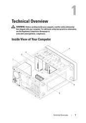
1 Technical Overview WARNING: Before working inside your computer, read the safety information that shipped with your computer. Inside View of Your Computer 4 3 2 1 5 6 Technical Overview 7 For additional safety best practices information, see the Regulatory Compliance Homepage at www.dell.com/regulatory_compliance.
1 Technical Overview WARNING: Before working inside your computer, read the safety information that shipped with your computer. Inside View of Your Computer 4 3 2 1 5 6 Technical Overview 7 For additional safety best practices information, see the Regulatory Compliance Homepage at www.dell.com/regulatory_compliance.
Service Manual
Page 11
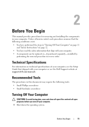
.... 1 Shut down the operating system. 2 Before You Begin This manual provides procedures for removing and installing the components in your computer, see the Dell Support website at support.dell.com/manuals. Unless otherwise noted, each procedure assumes that the following tools: • Small Phillips screwdriver • Small flat-blade screwdriver Turning Off...
.... 1 Shut down the operating system. 2 Before You Begin This manual provides procedures for removing and installing the components in your computer, see the Dell Support website at support.dell.com/manuals. Unless otherwise noted, each procedure assumes that the following tools: • Small Phillips screwdriver • Small flat-blade screwdriver Turning Off...
Service Manual
Page 12
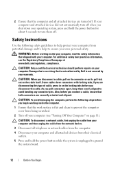
... your own personal safety. WARNING: Before working inside your computer, read the safety information that is not authorized by Dell is not covered by your computer (see the Regulatory Compliance Homepage at www.dell.com/regulatory_compliance. Also, before you are disconnecting this type of cable, press in on the cable itself. Safety...
... your own personal safety. WARNING: Before working inside your computer, read the safety information that is not authorized by Dell is not covered by your computer (see the Regulatory Compliance Homepage at www.dell.com/regulatory_compliance. Also, before you are disconnecting this type of cable, press in on the cable itself. Safety...
Service Manual
Page 13
CAUTION: Before touching anything inside your computer, ground yourself by touching an unpainted metal surface, such as the metal at the back of the computer. Before You Begin 13 While you work, periodically touch an unpainted metal surface to dissipate static electricity, which could harm internal components.
CAUTION: Before touching anything inside your computer, ground yourself by touching an unpainted metal surface, such as the metal at the back of the computer. Before You Begin 13 While you work, periodically touch an unpainted metal surface to dissipate static electricity, which could harm internal components.

Service Manual
Page 14
14 Before You Begin
14 Before You Begin
Service Manual
Page 15
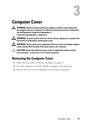
... Cover WARNING: Before working inside your computer, read the safety information that sufficient space exists to support the system with the cover removed-at www.dell.com/regulatory_compliance. WARNING: Do not operate your computer. For additional safety best practices information, see the Regulatory Compliance Homepage at least 30 cm (1 ft.) of...
... Cover WARNING: Before working inside your computer, read the safety information that sufficient space exists to support the system with the cover removed-at www.dell.com/regulatory_compliance. WARNING: Do not operate your computer. For additional safety best practices information, see the Regulatory Compliance Homepage at least 30 cm (1 ft.) of...
Service Manual
Page 16
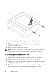
1 2 3 1 front of computer 2 computer cover 3 screws (2) 4 Release the computer cover by pulling it up , and then perform step 3 to step 5. NOTE: To remove the computer cover on the other side, lay the computer on its side with the slots located along the edge of the computer. 4 Press the computer cover down and slide it towards the front of the computer and lifting it away from the front of the computer until you feel a click or feel the computer cover securely installed. 16 Computer Cover Replacing the Computer Cover 1 Ensure that all cables are connected, and fold cables out ...
1 2 3 1 front of computer 2 computer cover 3 screws (2) 4 Release the computer cover by pulling it up , and then perform step 3 to step 5. NOTE: To remove the computer cover on the other side, lay the computer on its side with the slots located along the edge of the computer. 4 Press the computer cover down and slide it towards the front of the computer and lifting it away from the front of the computer until you feel a click or feel the computer cover securely installed. 16 Computer Cover Replacing the Computer Cover 1 Ensure that all cables are connected, and fold cables out ...
Service Manual
Page 17
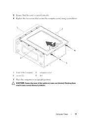
5 Ensure that the cover is seated correctly. 6 Replace the two screws that none of the computer 2 3 screws (2) 4 computer cover slot 7 Place the computer in an upright position. Blocking them would cause serious thermal problems. Computer Cover 17 CAUTION: Ensure that secure the computer cover, using a screwdriver. 1 2 4 3 1 front of the system air-vents are blocked.
5 Ensure that the cover is seated correctly. 6 Replace the two screws that none of the computer 2 3 screws (2) 4 computer cover slot 7 Place the computer in an upright position. Blocking them would cause serious thermal problems. Computer Cover 17 CAUTION: Ensure that secure the computer cover, using a screwdriver. 1 2 4 3 1 front of the system air-vents are blocked.

Service Manual
Page 18
18 Computer Cover
18 Computer Cover
Service Manual
Page 19
... 1 Follow the procedures in "Before You Begin" on page 11. 2 Remove the computer cover from both the sides (see the Regulatory Compliance Homepage at www.dell.com/regulatory_compliance. WARNING: To guard against electrical shock, always unplug your computer from the front panel. Front Bezel 19 For additional safety best practices information...
... 1 Follow the procedures in "Before You Begin" on page 11. 2 Remove the computer cover from both the sides (see the Regulatory Compliance Homepage at www.dell.com/regulatory_compliance. WARNING: To guard against electrical shock, always unplug your computer from the front panel. Front Bezel 19 For additional safety best practices information...
Service Manual
Page 20
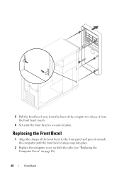
Replacing the Front Bezel 1 Align the clamps of the computer to the front panel and press it from the front bezel inserts. 6 Set aside the front bezel in a secure location. 5 Pull the front bezel away from the front of the front bezel to release it towards the computer until the front bezel clamps snap into place. 2 Replace the computer cover on both the sides (see "Replacing the Computer Cover" on page 16). 20 Front Bezel
Replacing the Front Bezel 1 Align the clamps of the computer to the front panel and press it from the front bezel inserts. 6 Set aside the front bezel in a secure location. 5 Pull the front bezel away from the front of the front bezel to release it towards the computer until the front bezel clamps snap into place. 2 Replace the computer cover on both the sides (see "Replacing the Computer Cover" on page 16). 20 Front Bezel
Service Manual
Page 21
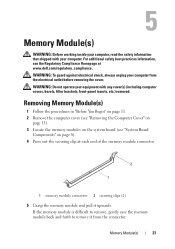
.... 2 Remove the computer cover (see "Removing the Computer Cover" on page 15). 3 Locate the memory modules on page 8). 4 Press out the securing clip at www.dell.com/regulatory_compliance. If the memory module is difficult to remove, gently ease the memory module back and forth to remove it upwards. Memory Module(s) 21...
.... 2 Remove the computer cover (see "Removing the Computer Cover" on page 15). 3 Locate the memory modules on page 8). 4 Press out the securing clip at www.dell.com/regulatory_compliance. If the memory module is difficult to remove, gently ease the memory module back and forth to remove it upwards. Memory Module(s) 21...
Service Manual
Page 22
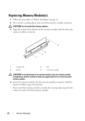
If you apply equal force to the memory module, press the memory module straight down into the connector while you insert the memory module correctly, the securing clips snap into position. Replacing Memory Module(s) 1 Follow the procedures in "Before You Begin" on the bottom of the memory module with the tab in the memory module connector. 4 3 2 1 1 cutouts (2) 3 notch 2 tab 4 memory module CAUTION: To avoid damage to each end of the memory module. 4 Insert the memory module into the memory module connector until the memory module snaps into the cutouts at each end of the ...
If you apply equal force to the memory module, press the memory module straight down into the connector while you insert the memory module correctly, the securing clips snap into position. Replacing Memory Module(s) 1 Follow the procedures in "Before You Begin" on the bottom of the memory module with the tab in the memory module connector. 4 3 2 1 1 cutouts (2) 3 notch 2 tab 4 memory module CAUTION: To avoid damage to each end of the memory module. 4 Insert the memory module into the memory module connector until the memory module snaps into the cutouts at each end of the ...
Service Manual
Page 23
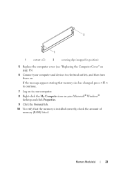
Memory Module(s) 23 If the message appears stating that the memory is installed correctly, check the amount of memory (RAM) listed. 2 1 1 cutouts (2) 2 securing clip (snapped in position) 5 Replace the computer cover (see "Replacing the Computer Cover" on page 16). 6 Connect your computer and devices to your Microsoft® Windows® desktop and click Properties. 9 Click the General tab. 10 To verify that memory size has changed, press to continue. 7 Log on to electrical outlets, and then turn them on your computer. 8 Right-click the My Computer icon on .
Memory Module(s) 23 If the message appears stating that the memory is installed correctly, check the amount of memory (RAM) listed. 2 1 1 cutouts (2) 2 securing clip (snapped in position) 5 Replace the computer cover (see "Replacing the Computer Cover" on page 16). 6 Connect your computer and devices to your Microsoft® Windows® desktop and click Properties. 9 Click the General tab. 10 To verify that memory size has changed, press to continue. 7 Log on to electrical outlets, and then turn them on your computer. 8 Right-click the My Computer icon on .

Service Manual
Page 24
24 Memory Module(s)
24 Memory Module(s)