Service Manual
Page 12
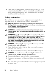
... network device. 3 Disconnect all telephone or network cables from the computer. 4 Disconnect your own personal safety. CAUTION: Only a certified service technician should perform repairs on the locking tabs before you disconnect a cable, pull on its connector or on its pull-tab, not on page 11). Damage due to ground the system board. 12 Before You Begin CAUTION: When you connect a cable...
... network device. 3 Disconnect all telephone or network cables from the computer. 4 Disconnect your own personal safety. CAUTION: Only a certified service technician should perform repairs on the locking tabs before you disconnect a cable, pull on its connector or on its pull-tab, not on page 11). Damage due to ground the system board. 12 Before You Begin CAUTION: When you connect a cable...
Service Manual
Page 30
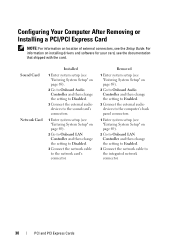
... location of external connectors, see the Setup Guide. Sound Card Network Card Installed 1 Enter system setup (see "Entering System Setup" on page 69). 2 Go to Onboard Audio Controller and then change the setting to Disabled. 3 Connect the external audio devices to the sound card's connectors. 1 Enter system setup (see "Entering System Setup" on page 69). 2 Go to Onboard LAN Controller and then change the setting to Disabled. 3 Connect the network cable to the integrated network connector. 30 PCI and PCI Express Cards Configuring Your Computer After Removing or Installing a PCI/PCI...
... location of external connectors, see the Setup Guide. Sound Card Network Card Installed 1 Enter system setup (see "Entering System Setup" on page 69). 2 Go to Onboard Audio Controller and then change the setting to Disabled. 3 Connect the external audio devices to the sound card's connectors. 1 Enter system setup (see "Entering System Setup" on page 69). 2 Go to Onboard LAN Controller and then change the setting to Disabled. 3 Connect the network cable to the integrated network connector. 30 PCI and PCI Express Cards Configuring Your Computer After Removing or Installing a PCI/PCI...
Service Manual
Page 33
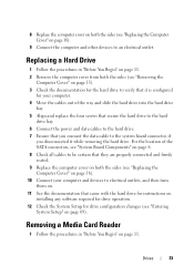
... are properly connected and firmly seated. 9 Replace the computer cover on both the sides (see "Replacing the Computer Cover" on page 16). 10 Connect your computer and devices to electrical outlets, and then turn them on. 11 See the documentation that came with the hard drive for instructions on installing any software required for drive operation. 12 Check the System Setup for drive configuration changes (see "Entering System Setup" on page...
... are properly connected and firmly seated. 9 Replace the computer cover on both the sides (see "Replacing the Computer Cover" on page 16). 10 Connect your computer and devices to electrical outlets, and then turn them on. 11 See the documentation that came with the hard drive for instructions on installing any software required for drive operation. 12 Check the System Setup for drive configuration changes (see "Entering System Setup" on page...
Service Manual
Page 69
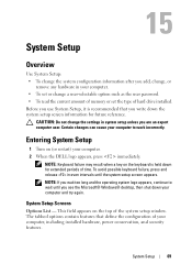
... set or change a user-selectable option such as the user password. • To read the current amount of memory or set the type of your computer. 2 When the DELL logo appears, press immediately. NOTE: Keyboard failure may result when a key on the top of time. This field appears on the keyboard is recommended that define the configuration of hard drive installed. System Setup Screens Options List - 15 System Setup Overview Use System Setup: • To change...
... set or change a user-selectable option such as the user password. • To read the current amount of memory or set the type of your computer. 2 When the DELL logo appears, press immediately. NOTE: Keyboard failure may result when a key on the top of time. This field appears on the keyboard is recommended that define the configuration of hard drive installed. System Setup Screens Options List - 15 System Setup Overview Use System Setup: • To change...
Service Manual
Page 71
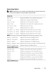
....(Has no connector) SATA-3 Displays the SATA drive connected to the SATA 1. System Info BIOS Info Displays the BIOS version and date information. Memory Technology Indicates the type of processor Level 3 cache. Processor L1 Cache Displays the amount of installed memory. SATA-1 Displays the SATA drive connected to the SATA 3. Advanced BIOS Features System Setup 71 Memory Installed Indicates the amount of processor Level 1 cache. Service Tag Displays the service tag of installed memory. System Displays the computer model number. Memory Speed...
....(Has no connector) SATA-3 Displays the SATA drive connected to the SATA 1. System Info BIOS Info Displays the BIOS version and date information. Memory Technology Indicates the type of processor Level 3 cache. Processor L1 Cache Displays the amount of installed memory. SATA-1 Displays the SATA drive connected to the SATA 3. Advanced BIOS Features System Setup 71 Memory Installed Indicates the amount of processor Level 1 cache. Service Tag Displays the service tag of installed memory. System Displays the computer model number. Memory Speed...
Service Manual
Page 73
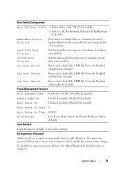
... and to access your computer. CD-ROM Boot Priority Set the optical drive boot priority, if multiple optical drives are installed. CDROM; Enabled (Enabled by default) 2nd Boot Device Removable; Network; Boot Device Configuration Boot Setting Config • Numlock Key-On; CDROM; Disabled (Removable by default) Auto Power On Date 0 Auto Power On Time 0:00:00 AC Recovery Last Power State; To disable the supervisor password, leave the Enter Password field blank and press . Hard Disk; Enabled (Disabled by default) Power Management Features ACPI Suspend Type S1...
... and to access your computer. CD-ROM Boot Priority Set the optical drive boot priority, if multiple optical drives are installed. CDROM; Enabled (Enabled by default) 2nd Boot Device Removable; Network; Boot Device Configuration Boot Setting Config • Numlock Key-On; CDROM; Disabled (Removable by default) Auto Power On Date 0 Auto Power On Time 0:00:00 AC Recovery Last Power State; To disable the supervisor password, leave the Enter Password field blank and press . Hard Disk; Enabled (Disabled by default) Power Management Features ACPI Suspend Type S1...
Service Manual
Page 74
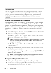
... a USB device such as a floppy drive, memory key, or CD-RW drive. 1 If you are booting to a USB device, connect the USB device to a USB connector. 2 Turn on the Drivers and Utilities disc, but you see "Entering System Setup" on page 69). 2 Use the arrow keys to highlight the Boot Device Configuration menu option and press to wait until you want the computer to boot from the optical drive so that is to a USB memory key, highlight USB Flash Device and press . You can run the Dell Diagnostics on...
... a USB device such as a floppy drive, memory key, or CD-RW drive. 1 If you are booting to a USB device, connect the USB device to a USB connector. 2 Turn on the Drivers and Utilities disc, but you see "Entering System Setup" on page 69). 2 Use the arrow keys to highlight the Boot Device Configuration menu option and press to wait until you want the computer to boot from the optical drive so that is to a USB memory key, highlight USB Flash Device and press . You can run the Dell Diagnostics on...
Setup Guide
Page 5
...Connect the Keyboard and Mouse 8 Connect the Power Cable 9 Connect the Network Cable (Optional 10 Press the Power Button 12 Set Up Microsoft Windows 13 Connect to the Internet (Optional 14 Using Your Dimension Desktop 16 Front View Features 16 Back View Features 20 Back Panel Connectors 22 Software Features 24 Dell DataSafe Online Backup 28 Dell Dock 29 Solving Problems 30 Beep Codes 30 Network Problems 31 Power Problems 31 Memory Problems 33 Lockups and Software Problems 34 Using Support Tools 36 Dell Support Center 36 System Messages 37 Hardware Troubleshooter 39 Dell...
...Connect the Keyboard and Mouse 8 Connect the Power Cable 9 Connect the Network Cable (Optional 10 Press the Power Button 12 Set Up Microsoft Windows 13 Connect to the Internet (Optional 14 Using Your Dimension Desktop 16 Front View Features 16 Back View Features 20 Back Panel Connectors 22 Software Features 24 Dell DataSafe Online Backup 28 Dell Dock 29 Solving Problems 30 Beep Codes 30 Network Problems 31 Power Problems 31 Memory Problems 33 Lockups and Software Problems 34 Using Support Tools 36 Dell Support Center 36 System Messages 37 Hardware Troubleshooter 39 Dell...
Setup Guide
Page 13
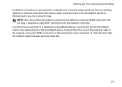
... plug a telephone cable (RJ11 connector) into the network connector. Connect the other end of your computer setup, but if you have an existing network or Internet connection that the network cable has been securely attached. 11 To connect your computer to a network or a broadband device, connect one end of the network cable to the network connector (RJ45 connector) on the back panel of the network cable to the network port or the broadband device. NOTE: Use only an Ethernet cable...
... plug a telephone cable (RJ11 connector) into the network connector. Connect the other end of your computer setup, but if you have an existing network or Internet connection that the network cable has been securely attached. 11 To connect your computer to a network or a broadband device, connect one end of the network cable to the network connector (RJ45 connector) on the back panel of the network cable to the network port or the broadband device. NOTE: Use only an Ethernet cable...
Setup Guide
Page 17
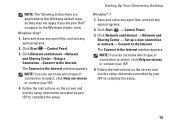
... open programs. 2. Save and close any open files, and exit any open programs. 2. Click Network and Internet → Network and Sharing Center → Set up a new connection or network→ Connect to the Internet window appears. Windows® 7 1. Follow the instructions on the screen and use the setup information provided by your ISP to complete the setup. 15 The Connect to the Internet. Setting Up Your Dimension Desktop NOTE: The following instructions are applicable to the Windows default...
... open programs. 2. Save and close any open files, and exit any open programs. 2. Click Network and Internet → Network and Sharing Center → Set up a new connection or network→ Connect to the Internet window appears. Windows® 7 1. Follow the instructions on the screen and use the setup information provided by your ISP to complete the setup. 15 The Connect to the Internet. Setting Up Your Dimension Desktop NOTE: The following instructions are applicable to the Windows default...
Setup Guide
Page 20
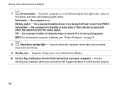
Turns the computer on or off or is on. Used to the hard drive. 9 FlexBay slot - Off - Supports a floppy drive and a Media Card Reader. 10 Service Tag and Express Service Code (located on page 31. 8 Hard drive activity light - Using Your Dimension Desktop 7 Power button - the computer is not receiving power. the computer is either in standby or sleep state or there may be an issue with either the system board or the power supply. Blinking amber - the computer...
Turns the computer on or off or is on. Used to the hard drive. 9 FlexBay slot - Off - Supports a floppy drive and a Media Card Reader. 10 Service Tag and Express Service Code (located on page 31. 8 Hard drive activity light - Using Your Dimension Desktop 7 Power button - the computer is not receiving power. the computer is either in standby or sleep state or there may be an issue with either the system board or the power supply. Blinking amber - the computer...
Setup Guide
Page 26
..., listen to create presentations, brochures, greeting cards, fliers, and spreadsheets. You can access websites, setup an e-mail account, and upload or download files. Optional software applications enable you to organize and create music and video files that can be recorded to the Internet, you can also edit and view digital photographs and images. Your optical disc drive may support multiple disc media formats including CDs and DVDs.
..., listen to create presentations, brochures, greeting cards, fliers, and spreadsheets. You can access websites, setup an e-mail account, and upload or download files. Optional software applications enable you to organize and create music and video files that can be recorded to the Internet, you can also edit and view digital photographs and images. Your optical disc drive may support multiple disc media formats including CDs and DVDs.
Setup Guide
Page 34
... display may not be a possible problem with either the system board or power supply. For assistance, contact Dell (see "Contacting Dell" on page 54). Solving Problems • Ensure that the power supply diagnostics light on the back of interference are: • Power, keyboard, and mouse extension cables. • Too many devices connected to a power strip. • Multiple power strips connected to resume normal operation. • There may be an issue with the power supply...
... display may not be a possible problem with either the system board or power supply. For assistance, contact Dell (see "Contacting Dell" on page 54). Solving Problems • Ensure that the power supply diagnostics light on the back of interference are: • Power, keyboard, and mouse extension cables. • Too many devices connected to a power strip. • Multiple power strips connected to resume normal operation. • There may be an issue with the power supply...
Setup Guide
Page 35
... the type of memory supported by your computer, see "Basic Specifications" on page 58. • Run the Dell Diagnostics (see "Dell Diagnostics" on the Dell Support website at support.dell.com) to see the Service Manual on page 39). • Reseat the memory modules (see if that resolves the problem. • See the software documentation for minimum memory requirements. If necessary, install additional memory (see the Service Manual on the Dell Support website at support.dell.com...
... the type of memory supported by your computer, see "Basic Specifications" on page 58. • Run the Dell Diagnostics (see "Dell Diagnostics" on the Dell Support website at support.dell.com) to see the Service Manual on page 39). • Reseat the memory modules (see if that resolves the problem. • See the software documentation for minimum memory requirements. If necessary, install additional memory (see the Service Manual on the Dell Support website at support.dell.com...
Setup Guide
Page 40
... - Disconnect the USB device. USB over current error - Using Support Tools No boot device available - Hard Drive SELF MONITORING SYSTEM has reported that you back up your boot device, ensure that the cables are connected and that the drive is installed properly and partitioned as a boot device. • Enter system setup and ensure that the boot sequence information is correct. See "Contacting Dell" on the system board might be enabled or disabled in the BIOS setup. Use an external power source to...
... - Disconnect the USB device. USB over current error - Using Support Tools No boot device available - Hard Drive SELF MONITORING SYSTEM has reported that you back up your boot device, ensure that the cables are connected and that the drive is installed properly and partitioned as a boot device. • Enter system setup and ensure that the boot sequence information is correct. See "Contacting Dell" on the system board might be enabled or disabled in the BIOS setup. Use an external power source to...
Setup Guide
Page 42
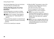
... Utilities disc. 40 Turn on page 54. 1. NOTE: If you wait too long and the operating system logo appears, continue to be working properly. 2. This will invoke the Pre-Boot System Assessment (PSA) in some computers. Using Support Tools Start the Dell Diagnostics from your hard drive or from the boot menu and press . Select Diagnostics from the Drivers and Utilities disc. NOTE: If your computer cannot display a screen image, see "Contacting Dell...
... Utilities disc. 40 Turn on page 54. 1. NOTE: If you wait too long and the operating system logo appears, continue to be working properly. 2. This will invoke the Pre-Boot System Assessment (PSA) in some computers. Using Support Tools Start the Dell Diagnostics from your hard drive or from the boot menu and press . Select Diagnostics from the Drivers and Utilities disc. NOTE: If your computer cannot display a screen image, see "Contacting Dell...
Setup Guide
Page 51
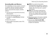
.... When the boot device list appears, highlight CD/DVD/CD-RW Drive and press . 7. Restoring Your Operating System NOTE: If you wait too long and the operating system logo appears, continue to Boot from CD-ROM. Press any open programs. 2. Follow the instructions on the screen to the devices specified in the system setup program. 6. Save and close any open files and exit any key to wait...
.... When the boot device list appears, highlight CD/DVD/CD-RW Drive and press . 7. Restoring Your Operating System NOTE: If you wait too long and the operating system logo appears, continue to Boot from CD-ROM. Press any open programs. 2. Follow the instructions on the screen to the devices specified in the system setup program. 6. Save and close any open files and exit any key to wait...
Setup Guide
Page 58
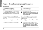
... support.dell.com the Service Manual on the Dell™ Support website at support.dell.com NOTE: In some countries, opening and replacing parts of your computer the Drivers and Utilities disc NOTE: Drivers and documentation updates can be found on the Dell Support website at support.dell.com. Finding More Information and Resources If you need to: reinstall your operating system find your system model number run a diagnostic program for your computer, reinstall desktop system software, or update drivers...
... support.dell.com the Service Manual on the Dell™ Support website at support.dell.com NOTE: In some countries, opening and replacing parts of your computer the Drivers and Utilities disc NOTE: Drivers and documentation updates can be found on the Dell Support website at support.dell.com. Finding More Information and Resources If you need to: reinstall your operating system find your system model number run a diagnostic program for your computer, reinstall desktop system software, or update drivers...
Setup Guide
Page 60
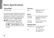
... for SATA DVD+/-RW Super Multi Drive one 3.5-inch drive bay for , and upgrading your computer. For more information regarding the configuration of your computer, click Start → Help and Support and select the option to view information about your computer. NOTE: Offerings may need when setting up, updating drivers for SATA hard drive Expansion Slots PCI Express x16 one slot supporting full-height card PCI one slot supporting full-height card 58 Basic Specifications System Model Dimension 2010...
... for SATA DVD+/-RW Super Multi Drive one 3.5-inch drive bay for , and upgrading your computer. For more information regarding the configuration of your computer, click Start → Help and Support and select the option to view information about your computer. NOTE: Offerings may need when setting up, updating drivers for SATA hard drive Expansion Slots PCI Express x16 one slot supporting full-height card PCI one slot supporting full-height card 58 Basic Specifications System Model Dimension 2010...
Setup Guide
Page 69
... power cable, do not have a voltage selection switch on the back panel and automatically detect the correct operating voltage. --A manual voltage selection switch Devices with an auto-sensing voltage circuit do not use adapter plugs that most closely matches the AC power available in your device is equipped with one pictured. For internal power sources, your location. CAUTION: To help avoid damaging a computer with a manual voltage selection switch, set...
... power cable, do not have a voltage selection switch on the back panel and automatically detect the correct operating voltage. --A manual voltage selection switch Devices with an auto-sensing voltage circuit do not use adapter plugs that most closely matches the AC power available in your device is equipped with one pictured. For internal power sources, your location. CAUTION: To help avoid damaging a computer with a manual voltage selection switch, set...


