Brocade 6520 Hardware Referencce Manual
Page 13
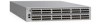
... and scalability requirements of an enterprise switch along with the appropriate licensing. Brocade 6520 Introduction Chapter 1 In this chapter •Brocade 6520 overview 1 •Port side of the Brocade 6520 3 •Non-port side of the Brocade 6520 4 Brocade 6520 overview The Brocade 6520 is only 24 inches deep and has airflow direction options. The first eight ports can order either port side...
... and scalability requirements of an enterprise switch along with the appropriate licensing. Brocade 6520 Introduction Chapter 1 In this chapter •Brocade 6520 overview 1 •Port side of the Brocade 6520 3 •Non-port side of the Brocade 6520 4 Brocade 6520 overview The Brocade 6520 is only 24 inches deep and has airflow direction options. The first eight ports can order either port side...
Brocade 6520 Hardware Referencce Manual
Page 14
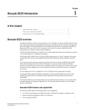
... • In-flight data compression and encryption on the first eight ports only. - There is accomplished at a switch level. 2 Brocade 6520 Hardware Reference Manual 53-1002705-01 Mirror ports (M_ports) and diagnostic ports (D_ports) must be configured for 10 Gbps for optimal bandwidth ...ports provides efficient link utilization and security. • Options for port side exhaust (default) or non-port side exhaust airflow for unicast data traffic types. • Brocade Fabric OS, which allows up to 7,500 km at 2 Gbps. • Support for cooling. • Virtual Fabric...
... • In-flight data compression and encryption on the first eight ports only. - There is accomplished at a switch level. 2 Brocade 6520 Hardware Reference Manual 53-1002705-01 Mirror ports (M_ports) and diagnostic ports (D_ports) must be configured for 10 Gbps for optimal bandwidth ...ports provides efficient link utilization and security. • Options for port side exhaust (default) or non-port side exhaust airflow for unicast data traffic types. • Brocade Fabric OS, which allows up to 7,500 km at 2 Gbps. • Support for cooling. • Virtual Fabric...
Brocade 6520 Hardware Referencce Manual
Page 17
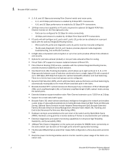
... a fully-configured Brocade 6520. Two 6 ft. Brocade 6520 Hardware Reference Manual 5 53-1002705-01 When you open the Brocade 6520 packaging, verify that no damage has occurred during shipping: • The Brocade 6520 switch, containing two power supplies and three fans (incorporating either non-port side exhaust or port side exhaust airflow as a standalone unit - Chapter Brocade 6520 Installation and Configuration...
... a fully-configured Brocade 6520. Two 6 ft. Brocade 6520 Hardware Reference Manual 5 53-1002705-01 When you open the Brocade 6520 packaging, verify that no damage has occurred during shipping: • The Brocade 6520 switch, containing two power supplies and three fans (incorporating either non-port side exhaust or port side exhaust airflow as a standalone unit - Chapter Brocade 6520 Installation and Configuration...
Brocade 6520 Hardware Referencce Manual
Page 20
...condensing, at 70ºC (158ºF) 0 to avoid intake of exhaust air. • Airflow requirements outlined in a rack, ensure the following environmental requirements are three rack kit options that accommodate the Brocade 6520, a four-post fixed rack kit, a two-post Telco rack kit, and a four-post ...sliding rail rack kit. Note that the requirements differ based on the direction of the airflow. • The ambient air temperature does not...
...condensing, at 70ºC (158ºF) 0 to avoid intake of exhaust air. • Airflow requirements outlined in a rack, ensure the following environmental requirements are three rack kit options that accommodate the Brocade 6520, a four-post fixed rack kit, a two-post Telco rack kit, and a four-post ...sliding rail rack kit. Note that the requirements differ based on the direction of the airflow. • The ambient air temperature does not...
Brocade 6520 Hardware Referencce Manual
Page 21
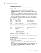
...routing port cables and other cables away from being bent to reduce potential tangling of ways; for backing up the switch configuration (optional) Brocade 6520 Hardware Reference Manual 9 53-1002705-01 The cables used in trunking groups must meet specific requirements, as required • Access to ... a reliable branch circuit connection and maintains ground at least 1 m (3.28 ft) of unexpected movement, such as a power strip. • Airflow and temperature requirements are met on the sides of the rack or patch panels to less than the minimum bend radius. • If you are...
...routing port cables and other cables away from being bent to reduce potential tangling of ways; for backing up the switch configuration (optional) Brocade 6520 Hardware Reference Manual 9 53-1002705-01 The cables used in trunking groups must meet specific requirements, as required • Access to ... a reliable branch circuit connection and maintains ground at least 1 m (3.28 ft) of unexpected movement, such as a power strip. • Airflow and temperature requirements are met on the sides of the rack or patch panels to less than the minimum bend radius. • If you are...
Brocade 6520 Hardware Referencce Manual
Page 32
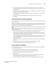
... cord is less than 40C and check for intake airflow blockage. Steady amber Steady green Power supply is not enabled. Check the power cord, current, voltage, and temperature to a functioning AC power source. No action required. 20 Brocade 6520 Hardware Reference Manual 53-1002705-01 No action required....the switch. 1 Power supply DC status LED 2 Power supply AC status LED 3 Fan status LED FIGURE 4 LEDs on non-port side of Brocade 6520 Table 8 describes the LEDs on the non-port side of hardware Recommended action Power supply AC input status (one bi-color LED) Flashing amber...
... cord is less than 40C and check for intake airflow blockage. Steady amber Steady green Power supply is not enabled. Check the power cord, current, voltage, and temperature to a functioning AC power source. No action required. 20 Brocade 6520 Hardware Reference Manual 53-1002705-01 No action required....the switch. 1 Power supply DC status LED 2 Power supply AC status LED 3 Fan status LED FIGURE 4 LEDs on non-port side of Brocade 6520 Table 8 describes the LEDs on the non-port side of hardware Recommended action Power supply AC input status (one bi-color LED) Flashing amber...
Brocade 6520 Hardware Referencce Manual
Page 33
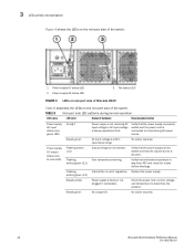
... more than 5 seconds) Fan assembly is not receiving power. Brocade 6520 Hardware Reference Manual 21 53-1002705-01 Fan assembly is complete: • Performs universal port configuration. • Initializes links. • Analyzes fabric. POST and boot-up time with mismatched airflow is present. • One or more of hardware Recommended action... POST diagnostics. • Initializes the operating system. • Initializes hardware. • Runs diagnostic tests on self-test (POST). Verify that has the correct airflow direction. • Replace the faulty fan assembly.
... more than 5 seconds) Fan assembly is not receiving power. Brocade 6520 Hardware Reference Manual 21 53-1002705-01 Fan assembly is complete: • Performs universal port configuration. • Initializes links. • Analyzes fabric. POST and boot-up time with mismatched airflow is present. • One or more of hardware Recommended action... POST diagnostics. • Initializes the operating system. • Initializes hardware. • Runs diagnostic tests on self-test (POST). Verify that has the correct airflow direction. • Replace the faulty fan assembly.
Brocade 6520 Hardware Referencce Manual
Page 39
...replacement 35 Removal and replacement introduction NOTE Read the "Installation and safety considerations" before servicing. A new FRU must have the same airflow symbol (E or I) to be removed and replaced without special tools. You can use external labels as the FRU being replaced.... field-replaceable units (FRUs) for qualified service personnel. This applies to Figure 7. Brocade 6520 Hardware Reference Manual 27 53-1002705-01 The field-replaceable units (FRUs) in the Brocade 6520 can continue operating during the FRU replacement if the conditions specified in or exhausts air...
...replacement 35 Removal and replacement introduction NOTE Read the "Installation and safety considerations" before servicing. A new FRU must have the same airflow symbol (E or I) to be removed and replaced without special tools. You can use external labels as the FRU being replaced.... field-replaceable units (FRUs) for qualified service personnel. This applies to Figure 7. Brocade 6520 Hardware Reference Manual 27 53-1002705-01 The field-replaceable units (FRUs) in the Brocade 6520 can continue operating during the FRU replacement if the conditions specified in or exhausts air...

Brocade 6520 Hardware Referencce Manual
Page 40
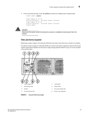
...power on the cord. • In Web Tools, click the Power Status icon. 28 Brocade 6520 Hardware Reference Manual 53-1002705-01 Refer to the console. Power supply removal and replacement The Brocade 6520 has two power supplies, as power supply #2 and power supply #1. This symbol should be...If a mismatched power supply or fan is installed by mistake, a critical error message is operating. 4 Power supply removal and replacement : E AIRFLOW AIRFLOW FIGURE 7 Examples of the power supplies: • Check the power supply AC status and DC status LEDs. This unit pulls air in the ...
...power on the cord. • In Web Tools, click the Power Status icon. 28 Brocade 6520 Hardware Reference Manual 53-1002705-01 Refer to the console. Power supply removal and replacement The Brocade 6520 has two power supplies, as power supply #2 and power supply #1. This symbol should be...If a mismatched power supply or fan is installed by mistake, a critical error message is operating. 4 Power supply removal and replacement : E AIRFLOW AIRFLOW FIGURE 7 Examples of the power supplies: • Check the power supply AC status and DC status LEDs. This unit pulls air in the ...
Brocade 6520 Hardware Referencce Manual
Page 41
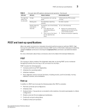
... completely remove power from all power sources to Figure 8 for the location of the airflow label. 1 Power supply #2 2 Grounding screw 3 Handle 4 AC input status LED FIGURE 8 Brocade 6520 power supply 5 Locking tab 6 Airflow label 7 DC output status LED 8 Power cord receptacle Brocade 6520 Hardware Reference Manual 29 53-1002705-01 Time and items required Replacing a power...
... completely remove power from all power sources to Figure 8 for the location of the airflow label. 1 Power supply #2 2 Grounding screw 3 Handle 4 AC input status LED FIGURE 8 Brocade 6520 power supply 5 Locking tab 6 Airflow label 7 DC output status LED 8 Power cord receptacle Brocade 6520 Hardware Reference Manual 29 53-1002705-01 Time and items required Replacing a power...
Brocade 6520 Hardware Referencce Manual
Page 42
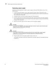
...new power supply into the power supply to power on the power supply to pull it is likely because the new power supply has a mismatched airflow. 5. CAUTION Do not force the installation. If the power circuit was on the locking tab. 4. Refer to avoid catching a finger on before...the chassis until the locking tab engages. CAUTION If you observe that the other power supply (the one not being replaced. 3. To leave the Brocade 6520 in a Brocade 6520. Pull the power supply out slowly to Figure 9 for at least four seconds and has a steady green status LED. 2. 4 Power supply ...
...new power supply into the power supply to power on the power supply to pull it is likely because the new power supply has a mismatched airflow. 5. CAUTION Do not force the installation. If the power circuit was on the locking tab. 4. Refer to avoid catching a finger on before...the chassis until the locking tab engages. CAUTION If you observe that the other power supply (the one not being replaced. 3. To leave the Brocade 6520 in a Brocade 6520. Pull the power supply out slowly to Figure 9 for at least four seconds and has a steady green status LED. 2. 4 Power supply ...
Brocade 6520 Hardware Referencce Manual
Page 44
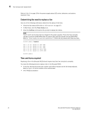
...4 and 5 are the fans that has the same part number and airflow indicator as the fan being replaced. You need to replace a fan Use one of the following items to replace a fan in the Brocade 6520 should require less than two minutes to complete. Determining the need the following... methods to display fan status. These two fans normally operate at the prompt to determine the status of the airflow label • A #1 Phillips screwdriver 32 Brocade 6520 Hardware Reference Manual 53-1002705-01 br6520:admin> fanshow Fan 1 is Ok, speed is 1965 RPM Fan 2 is Ok,...
...4 and 5 are the fans that has the same part number and airflow indicator as the fan being replaced. You need to replace a fan Use one of the following items to replace a fan in the Brocade 6520 should require less than two minutes to complete. Determining the need the following... methods to display fan status. These two fans normally operate at the prompt to determine the status of the airflow label • A #1 Phillips screwdriver 32 Brocade 6520 Hardware Reference Manual 53-1002705-01 br6520:admin> fanshow Fan 1 is Ok, speed is 1965 RPM Fan 2 is Ok,...
Brocade 6520 Hardware Referencce Manual
Page 45
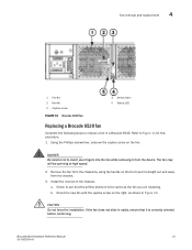
... screw on the fan. CAUTION Do not force the installation. b. Brocade 6520 Hardware Reference Manual 33 53-1002705-01 Refer to replace a fan in the chassis: a. Fan removal and replacement 4 1 Fan #3 2 Handle 3 Captive screw FIGURE 10 Brocade 6520 fan 4 Airflow label 5 Status LED Replacing a Brocade 6520 fan Complete the following steps to Figure 11 for this procedure. 1.
... screw on the fan. CAUTION Do not force the installation. b. Brocade 6520 Hardware Reference Manual 33 53-1002705-01 Refer to replace a fan in the chassis: a. Fan removal and replacement 4 1 Fan #3 2 Handle 3 Captive screw FIGURE 10 Brocade 6520 fan 4 Airflow label 5 Status LED Replacing a Brocade 6520 fan Complete the following steps to Figure 11 for this procedure. 1.
Brocade 6520 Hardware Referencce Manual
Page 46
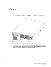
... status. Gently push the fan into the chassis until it is likely because the new fan has a mismatched airflow. FIGURE 11 Inserting the fan in the Brocade 6520 4. Optionally, if using the Web Tools application. 34 Brocade 6520 Hardware Reference Manual 53-1002705-01 d. 4 Fan removal and replacement CAUTION If you observe that the fan...
... status. Gently push the fan into the chassis until it is likely because the new fan has a mismatched airflow. FIGURE 11 Inserting the fan in the Brocade 6520 4. Optionally, if using the Web Tools application. 34 Brocade 6520 Hardware Reference Manual 53-1002705-01 d. 4 Fan removal and replacement CAUTION If you observe that the fan...
Brocade 6520 Hardware Referencce Manual
Page 67
Index Numerics 10 Gbps support, 2 A access NTP server, 15 airflow labels, 27 mismatch warning, 28 options, 2 B base model, 5 boot flash memory, 41 boot-up, 21 Brocade Advanced Web Tools, 25 Brocade Network Advisor, 25 BSMI statement (Taiwan), 45 C cable management, 9 Canadian requirements, 45 caution statements, ...translated, 51 CE statement, 45 chassisShow command, 28, 31, 34 China class A statement, 44 China RoHS, 47 CLI, 25 Brocade 6520 Hardware Reference Manual 53-1002705-01 command chassisShow, 28, 31, 34 date, 14 diagDisablePost, 21 errShow, 22 fanShow, 32, 34 fastboot, 21...
Index Numerics 10 Gbps support, 2 A access NTP server, 15 airflow labels, 27 mismatch warning, 28 options, 2 B base model, 5 boot flash memory, 41 boot-up, 21 Brocade Advanced Web Tools, 25 Brocade Network Advisor, 25 BSMI statement (Taiwan), 45 C cable management, 9 Canadian requirements, 45 caution statements, ...translated, 51 CE statement, 45 chassisShow command, 28, 31, 34 China class A statement, 44 China RoHS, 47 CLI, 25 Brocade 6520 Hardware Reference Manual 53-1002705-01 command chassisShow, 28, 31, 34 date, 14 diagDisablePost, 21 errShow, 22 fanShow, 32, 34 fastboot, 21...
Brocade 6520 Hardware Referencce Manual
Page 68
...port specifications, 41 ports, 3 Fibre Channel Routing (FCR), 2 field-replaceable units, see FRUs front panel LEDs, 17 FRUs airflow warning, 28 fan, replacing, 31 power supply, replacing, 28 removing and replacing, 27 transceivers, replacing, 35 G general ... ISL trunking, 15 items included, 5 J Japan DENAN statement, 43 K KCC statement (Republic of Korea), 43 L labels, airflow, 27 laser compliance, 45 latency, FC port-to-port, 3 LEDs, 3 activity, 17 Ethernet port, 18 fan indications, ... local clock, 15 LOCL, 15 logging timestamp, 12 Brocade 6520 Hardware Reference Manual 53-1002705-01
...port specifications, 41 ports, 3 Fibre Channel Routing (FCR), 2 field-replaceable units, see FRUs front panel LEDs, 17 FRUs airflow warning, 28 fan, replacing, 31 power supply, replacing, 28 removing and replacing, 27 transceivers, replacing, 35 G general ... ISL trunking, 15 items included, 5 J Japan DENAN statement, 43 K KCC statement (Republic of Korea), 43 L labels, airflow, 27 laser compliance, 45 latency, FC port-to-port, 3 LEDs, 3 activity, 17 Ethernet port, 18 fan indications, ... local clock, 15 LOCL, 15 logging timestamp, 12 Brocade 6520 Hardware Reference Manual 53-1002705-01
Message Reference Supporting Fabric OS v7.1.0
Page 301
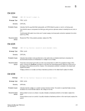
Sensor(s) above maximum limits. Make sure there are likely a hardware problem on and is composed of the airflow around the chassis. EM-1006 Message has faulted. Sensor(s) below minimum limits. EM-1004 5 EM-1004 Message failed to identify the unit, slot... problem occurs on a blade, it usually indicates a hardware problem on the blade; EM-1005 Message has faulted. Recommended Action Reseat the FRU. The Brocade 300 switch has 4 fans and 1 power supply, but these parts cannot be replaced: the entire switch is too low. replace the blade. replace the...
Sensor(s) above maximum limits. Make sure there are likely a hardware problem on and is composed of the airflow around the chassis. EM-1006 Message has faulted. Sensor(s) below minimum limits. EM-1004 5 EM-1004 Message failed to identify the unit, slot... problem occurs on a blade, it usually indicates a hardware problem on the blade; EM-1005 Message has faulted. Recommended Action Reseat the FRU. The Brocade 300 switch has 4 fans and 1 power supply, but these parts cannot be replaced: the entire switch is too low. replace the blade. replace the...
Message Reference Supporting Fabric OS v7.1.0
Page 460
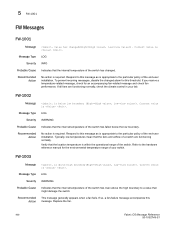
.... Typically, low temperatures mean that the internal temperature of the end-user installation. Message Type LOG Severity INFO Probable Cause Indicates that the fans and airflow of the switch has fallen below low boundary (High=, Low=). If so, a fan-failure message accompanies this threshold. 5 FW-1001 FW Messages FW-1001 Message...
.... Typically, low temperatures mean that the internal temperature of the end-user installation. Message Type LOG Severity INFO Probable Cause Indicates that the fans and airflow of the switch has fallen below low boundary (High=, Low=). If so, a fan-failure message accompanies this threshold. 5 FW-1001 FW Messages FW-1001 Message...
Message Reference Supporting Fabric OS v7.1.0
Page 585
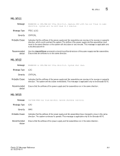
...moving in the same direction. Message Type LOG Severity CRITICAL Probable Cause Indicates that the airflows run in the reverse or opposite direction. This message is applicable only to the Brocade 6510. HIL-1613 Message PSU-FAN FRUS Air Flow matched. Recommended Action Ensure that the... or opposite direction, which could overheat the system. Recommended Action Ensure that the airflows of the power supply and fan assemblies run in the same direction. The system continues to the Brocade 6510. System shut down in PSU-FAN Air Flow direction. Fabric OS Message ...
...moving in the same direction. Message Type LOG Severity CRITICAL Probable Cause Indicates that the airflows run in the reverse or opposite direction. This message is applicable only to the Brocade 6510. HIL-1613 Message PSU-FAN FRUS Air Flow matched. Recommended Action Ensure that the... or opposite direction, which could overheat the system. Recommended Action Ensure that the airflows of the power supply and fan assemblies run in the same direction. The system continues to the Brocade 6510. System shut down in PSU-FAN Air Flow direction. Fabric OS Message ...
MIB Reference Supporting Fabric OS v7.1.0
Page 232
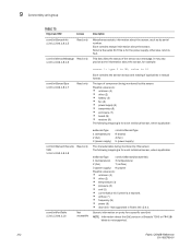
...this sensor. Not supported in textual format. It may also provide some information about the GbE ports on a Brocade 7500 or FR4-18i blade is for the power supply; The type of the sensor as its serial number....information on ports for a specific connUnit NOTE: Information about the sensor, for each individual sensor, where applicable: swSensorType connUnitSensorCharacteristic 1 (temperature) 3 (temperature) 2 (fan) 7 (airflow) 3 (power supply) 9 (power) Possible values are : • unknown (1) • other (2) • temperature (3) • pressure (4) • emf (5) ...
...this sensor. Not supported in textual format. It may also provide some information about the GbE ports on a Brocade 7500 or FR4-18i blade is for the power supply; The type of the sensor as its serial number....information on ports for a specific connUnit NOTE: Information about the sensor, for each individual sensor, where applicable: swSensorType connUnitSensorCharacteristic 1 (temperature) 3 (temperature) 2 (fan) 7 (airflow) 3 (power supply) 9 (power) Possible values are : • unknown (1) • other (2) • temperature (3) • pressure (4) • emf (5) ...