Administrator's Guide Supporting Fabric OS 7.1.0
Page 103
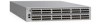
... manual of each slot in using an account with admin permissions. 2. Refer to verify the model of the DCX and obtain a listing of the switch power supplies.
... manual of each slot in using an account with admin permissions. 2. Refer to verify the model of the DCX and obtain a listing of the switch power supplies.
Brocade 6520 Hardware Referencce Manual
Page 3
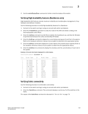
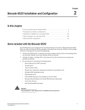
... technical help xi Document feedback xii Chapter 1 Brocade 6520 Introduction In this chapter 1 Brocade 6520 overview 1 Brocade 6520 features and capabilities 1 Brocade 6520 components 3 Port side of the Brocade 6520 3 Non-port side of the Brocade 6520 4 Chapter 2 Brocade 6520 Installation and Configuration In this chapter 5 Items included with the Brocade 6520 5 Installation and safety considerations 6 ESD precautions 6 Electrical considerations 6 Power supply specifications 6 Environmental considerations 8 Rack considerations 8 Recommendations...
... technical help xi Document feedback xii Chapter 1 Brocade 6520 Introduction In this chapter 1 Brocade 6520 overview 1 Brocade 6520 features and capabilities 1 Brocade 6520 components 3 Port side of the Brocade 6520 3 Non-port side of the Brocade 6520 4 Chapter 2 Brocade 6520 Installation and Configuration In this chapter 5 Items included with the Brocade 6520 5 Installation and safety considerations 6 ESD precautions 6 Electrical considerations 6 Power supply specifications 6 Environmental considerations 8 Rack considerations 8 Recommendations...
Brocade 6520 Hardware Referencce Manual
Page 4
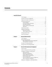
... 17 LED locations 17 POST and boot-up specifications 21 POST 21 Boot-up 21 Interpreting POST results 22 Brocade 6520 maintenance 22 Installing an SFP+ transceiver 22 Diagnostic tests 24 Brocade 6520 management 24 Removal and Replacement of Power Supplies and Fans In this chapter 27 Removal and replacement introduction 27 Before beginning replacement 27...
... 17 LED locations 17 POST and boot-up specifications 21 POST 21 Boot-up 21 Interpreting POST results 22 Brocade 6520 maintenance 22 Installing an SFP+ transceiver 22 Diagnostic tests 24 Brocade 6520 management 24 Removal and Replacement of Power Supplies and Fans In this chapter 27 Removal and replacement introduction 27 Before beginning replacement 27...

Brocade 6520 Hardware Referencce Manual
Page 7
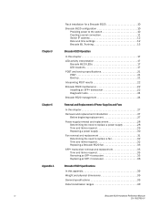
... and scenarios is organized to -day operational procedures for using the switch. • Chapter 4, "Removal and Replacement of Power Supplies and Fans" provides procedures for removing and replacing the field-replaceable units (FRUs). • Appendix A, "Brocade 6520 Specifications" provides tables of physical, environmental, and general specifications, helpful for quick lookup. • Appendix B, "Caution and...
... and scenarios is organized to -day operational procedures for using the switch. • Chapter 4, "Removal and Replacement of Power Supplies and Fans" provides procedures for removing and replacing the field-replaceable units (FRUs). • Appendix A, "Brocade 6520 Specifications" provides tables of physical, environmental, and general specifications, helpful for quick lookup. • Appendix B, "Caution and...
Brocade 6520 Hardware Referencce Manual
Page 15
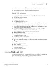
...232 console (serial) port with battery. Brocade 6520 Hardware Reference Manual 3 53-1002705-01 Figure 1 shows the port side of the supportSave command, and storage for configuration uploads and downloads. • Two hot-swappable, 80+ Platinum certified, redundant power supplies. • Three hot-swappable fan FRUs....and activity status. • Two LEDs per power supply: one green for AC line in status and one green/amber for firmware updates, output of the Brocade 6520. Port side of the Brocade 6520 The port side of the Brocade 6520 includes the system status LED, console port, ...
...232 console (serial) port with battery. Brocade 6520 Hardware Reference Manual 3 53-1002705-01 Figure 1 shows the port side of the supportSave command, and storage for configuration uploads and downloads. • Two hot-swappable, 80+ Platinum certified, redundant power supplies. • Three hot-swappable fan FRUs....and activity status. • Two LEDs per power supply: one green for AC line in status and one green/amber for firmware updates, output of the Brocade 6520. Port side of the Brocade 6520 The port side of the Brocade 6520 includes the system status LED, console port, ...

Brocade 6520 Hardware Referencce Manual
Page 16
1 Non-port side of the Brocade 6520 1 System power LED 2 System status LED 3 USB port 4 FC ports 0-7 (all LEDs above) 5 FC ports 8-47 6 FC ports 48-95 7 Switch ID pull-out tab 8 Management Ethernet port with LEDs 9 Serial console port FIGURE 1 Port side view of the Brocade 6520 Non-port side of the Brocade 6520 Figure 2 shows the non-port side of the Brocade 6520, which contains the power supplies (including the AC power receptacle) and fans. 1 Power supplies with integral fans 2 Fans FIGURE 2 Non-port side of the Brocade 6520 4 Brocade 6520 Hardware Reference Manual 53-1002705-01
1 Non-port side of the Brocade 6520 1 System power LED 2 System status LED 3 USB port 4 FC ports 0-7 (all LEDs above) 5 FC ports 8-47 6 FC ports 48-95 7 Switch ID pull-out tab 8 Management Ethernet port with LEDs 9 Serial console port FIGURE 1 Port side view of the Brocade 6520 Non-port side of the Brocade 6520 Figure 2 shows the non-port side of the Brocade 6520, which contains the power supplies (including the AC power receptacle) and fans. 1 Power supplies with integral fans 2 Fans FIGURE 2 Non-port side of the Brocade 6520 4 Brocade 6520 Hardware Reference Manual 53-1002705-01
Brocade 6520 Hardware Referencce Manual
Page 17
... Reference Manual 5 53-1002705-01 When you open the Brocade 6520 packaging, verify that no damage has occurred during shipping: • The Brocade 6520 switch, containing two power supplies and three fans (incorporating either non-port side exhaust or port side exhaust airflow as ordered) • 16 Gbps, 10 Gbps, or 8 Gbps SFP+ transceivers ...
... Reference Manual 5 53-1002705-01 When you open the Brocade 6520 packaging, verify that no damage has occurred during shipping: • The Brocade 6520 switch, containing two power supplies and three fans (incorporating either non-port side exhaust or port side exhaust airflow as ordered) • 16 Gbps, 10 Gbps, or 8 Gbps SFP+ transceivers ...
Brocade 6520 Hardware Referencce Manual
Page 18
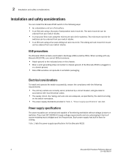
...In an EIA rack using the mid-mount rack kit for switches. ESD precautions The Brocade 6520 contains electrostatic discharge (ESD) sensitive FRUs. Power supply specifications The power supplies are autoranging in terms of functioning worldwide without voltage jumpers or switches. The rack mount... grounding strap connected to chassis ground (if the Brocade 6520 is plugged in) or a bench ground. • Store ESD-sensitive components in antistatic packaging. Each power supply has built-in fans for the Brocade 6520. 6 Brocade 6520 Hardware Reference Manual 53-1002705-01 The sliding rail...
...In an EIA rack using the mid-mount rack kit for switches. ESD precautions The Brocade 6520 contains electrostatic discharge (ESD) sensitive FRUs. Power supply specifications The power supplies are autoranging in terms of functioning worldwide without voltage jumpers or switches. The rack mount... grounding strap connected to chassis ground (if the Brocade 6520 is plugged in) or a bench ground. • Store ESD-sensitive components in antistatic packaging. Each power supply has built-in fans for the Brocade 6520. 6 Brocade 6520 Hardware Reference Manual 53-1002705-01 The sliding rail...

Brocade 6520 Hardware Referencce Manual
Page 19
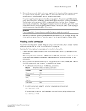
...929 1343.8552 395 1333.6228 394 1319.9796 390 1313.158 388 1347.266 1343.8552 1330.212 1323.3904 Brocade 6520 Hardware Reference Manual 7 53-1002705-01 switch autosenses input voltage. typical Typical: All ports configured with ELOAD, Traffic Running... 0.998 0.953 1545.0924 456 1555.3248 TABLE 4 Power consumption - TABLE 2 Power consumption - Installation and safety considerations 2 TABLE 1 Power supply specifications Specification Value Input voltage Input frequency Inrush current Input line protection Maximum power supply output (each) Range: 90-264 VAC Auto-volt, ...
...929 1343.8552 395 1333.6228 394 1319.9796 390 1313.158 388 1347.266 1343.8552 1330.212 1323.3904 Brocade 6520 Hardware Reference Manual 7 53-1002705-01 switch autosenses input voltage. typical Typical: All ports configured with ELOAD, Traffic Running... 0.998 0.953 1545.0924 456 1555.3248 TABLE 4 Power consumption - TABLE 2 Power consumption - Installation and safety considerations 2 TABLE 1 Power supply specifications Specification Value Input voltage Input frequency Inrush current Input line protection Maximum power supply output (each) Range: 90-264 VAC Auto-volt, ...
Brocade 6520 Hardware Referencce Manual
Page 23
...the AC status light on separate circuits to Figure 1 on the workstation. 2. Refer to protect against AC failure. Brocade 6520 configuration 2 1. If the second power supply IS plugged into a power source, then both power supplies in . The system status LED on a PC, or TERM, TIP, or Kermit in use, use the ...the following string at the prompt: tip /dev/ttya -9600 Brocade 6520 Hardware Reference Manual 11 53-1002705-01 Connect the serial cable to the serial port on the switch and to power sources on the power supply will be out and the DC status light will be green....
...the AC status light on separate circuits to Figure 1 on the workstation. 2. Refer to protect against AC failure. Brocade 6520 configuration 2 1. If the second power supply IS plugged into a power source, then both power supplies in . The system status LED on a PC, or TERM, TIP, or Kermit in use, use the ...the following string at the prompt: tip /dev/ttya -9600 Brocade 6520 Hardware Reference Manual 11 53-1002705-01 Connect the serial cable to the serial port on the switch and to power sources on the power supply will be out and the DC status light will be green....

Brocade 6520 Hardware Referencce Manual
Page 29
...-up at any time, even when a cable is inserted and the link is active. Brocade 6520 LEDs The Brocade 6520 has the following LEDs: • One system status LED (bicolor: green/amber). • One power status LED (green). • Two Ethernet port LEDs (green). • One port... • Two power supply status LEDs per power supply (AC indicator is bicolor: green/amber and DC indicator is normal; it does not indicate a problem unless the LEDs do not light up specifications 21 •Interpreting POST results 22 •Brocade 6520 maintenance 22 •Brocade 6520 management 24 LED ...
...-up at any time, even when a cable is inserted and the link is active. Brocade 6520 LEDs The Brocade 6520 has the following LEDs: • One system status LED (bicolor: green/amber). • One power status LED (green). • Two Ethernet port LEDs (green). • One port... • Two power supply status LEDs per power supply (AC indicator is bicolor: green/amber and DC indicator is normal; it does not indicate a problem unless the LEDs do not light up specifications 21 •Interpreting POST results 22 •Brocade 6520 maintenance 22 •Brocade 6520 management 24 LED ...
Brocade 6520 Hardware Referencce Manual
Page 30
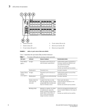
...your switch service provider. Contact your switch service provider. 18 Brocade 6520 Hardware Reference Manual 53-1002705-01 The switch is off or there is on and has completed booting. this status including a single power supply failure, a fan failure, or one or more than ... has been exceeded. A system fault has occurred. A number of Brocade 6520 Table 7 describes the port side LEDs and their behavior. Contact your power source is on. properly. Power cycle the switch. 3 LED activity interpretation 1 System power LED 2 System status LED 3 FC port status LED (port 0)...
...your switch service provider. Contact your switch service provider. 18 Brocade 6520 Hardware Reference Manual 53-1002705-01 The switch is off or there is on and has completed booting. this status including a single power supply failure, a fan failure, or one or more than ... has been exceeded. A system fault has occurred. A number of Brocade 6520 Table 7 describes the port side LEDs and their behavior. Contact your power source is on. properly. Power cycle the switch. 3 LED activity interpretation 1 System power LED 2 System status LED 3 FC port status LED (port 0)...
Brocade 6520 Hardware Referencce Manual
Page 32
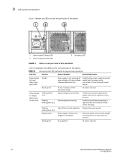
...side of the switch. 1 Power supply DC status LED 2 Power supply AC status LED 3 Fan status LED FIGURE 4 LEDs on non-port side of Brocade 6520 Table 8 describes the LEDs on the non-port side of regulation. No action required. Verify that the power supply is fully seated and that ...is not enabled. DC output OK. No action required. 20 Brocade 6520 Hardware Reference Manual 53-1002705-01 Steady green AC input voltage is secured. Power supply DC output status (one green LED) No light Power supply is not receiving AC input voltage or AC input voltage is connected...
...side of the switch. 1 Power supply DC status LED 2 Power supply AC status LED 3 Fan status LED FIGURE 4 LEDs on non-port side of Brocade 6520 Table 8 describes the LEDs on the non-port side of regulation. No action required. Verify that the power supply is fully seated and that ...is not enabled. DC output OK. No action required. 20 Brocade 6520 Hardware Reference Manual 53-1002705-01 Steady green AC input voltage is secured. Power supply DC output status (one green LED) No light Power supply is not receiving AC input voltage or AC input voltage is connected...
Brocade 6520 Hardware Referencce Manual
Page 39
...replaced without special tools. Both the power supply and fan FRUs are labeled with either a port-side air exhaust or a port-side air intake. ATTENTION All fans and power supplies must have the same part number (P/N) as a guide. The Brocade 6520 can continue operating during the FRU... replacement if the conditions specified in this chapter •Removal and replacement introduction 27 •Power supply removal and replacement 28 •...
...replaced without special tools. Both the power supply and fan FRUs are labeled with either a port-side air exhaust or a port-side air intake. ATTENTION All fans and power supplies must have the same part number (P/N) as a guide. The Brocade 6520 can continue operating during the FRU... replacement if the conditions specified in this chapter •Removal and replacement introduction 27 •Power supply removal and replacement 28 •...

Brocade 6520 Hardware Referencce Manual
Page 40
..., there is sent to "LED locations" on page 20 for the power supply status LED colors, behaviors, and actions required, if any part of the power supplies: • Check the power supply AC status and DC status LEDs. Power supply removal and replacement The Brocade 6520 has two power supplies, as power supply #2 and power supply #1. This is replaced. This unit pulls air in operational condition...
..., there is sent to "LED locations" on page 20 for the power supply status LED colors, behaviors, and actions required, if any part of the power supplies: • Check the power supply AC status and DC status LEDs. Power supply removal and replacement The Brocade 6520 has two power supplies, as power supply #2 and power supply #1. This is replaced. This unit pulls air in operational condition...
Brocade 6520 Hardware Referencce Manual
Page 41
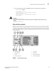
Time and items required Replacing a power supply in a Brocade 6520 you need a new power supply that has the same part number and airflow indicator as the power supply being replaced. To replace a power supply in the Brocade 6520 should require less than two minutes to complete. Refer to completely remove power from the chassis. Power supply removal and replacement 4 • At the command prompt, enter the...
Time and items required Replacing a power supply in a Brocade 6520 you need a new power supply that has the same part number and airflow indicator as the power supply being replaced. To replace a power supply in the Brocade 6520 should require less than two minutes to complete. Refer to completely remove power from the chassis. Power supply removal and replacement 4 • At the command prompt, enter the...
Brocade 6520 Hardware Referencce Manual
Page 42
... slowly to avoid catching a finger on the power supply to power on before continuing. If the power supply does not slide in a Brocade 6520. Plug the power cord into the chassis until the locking tab engages. To leave the Brocade 6520 in service while replacing a power supply, verify that is likely because the new power supply has a mismatched airflow. 5. CAUTION If you observe that...
... slowly to avoid catching a finger on the power supply to power on before continuing. If the power supply does not slide in a Brocade 6520. Plug the power cord into the chassis until the locking tab engages. To leave the Brocade 6520 in service while replacing a power supply, verify that is likely because the new power supply has a mismatched airflow. 5. CAUTION If you observe that...
Brocade 6520 Hardware Referencce Manual
Page 43
... use the chassisShow command. Optionally, if using the Web Tools application. The power supply status can also be replaced. Because the cooling system relies on the new power supply display steady green while the Brocade 6520 is operating (refer to display the status. Brocade 6520 Hardware Reference Manual 31 53-1002705-01 There are not steady green, ensure...
... use the chassisShow command. Optionally, if using the Web Tools application. The power supply status can also be replaced. Because the cooling system relies on the new power supply display steady green while the Brocade 6520 is operating (refer to display the status. Brocade 6520 Hardware Reference Manual 31 53-1002705-01 There are not steady green, ensure...
Brocade 6520 Hardware Referencce Manual
Page 44
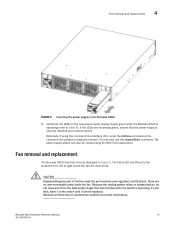
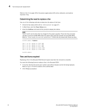
...20 for the location of the following items to replace a fan in the Brocade 6520 should require less than two minutes to complete. Refer to "Power supply removal and replacement" if there are integral to the power supplies. You need to replace a fan Use one of the airflow label &#...8226; A #1 Phillips screwdriver 32 Brocade 6520 Hardware Reference Manual 53-1002705-01 4 Fan removal and...
...20 for the location of the following items to replace a fan in the Brocade 6520 should require less than two minutes to complete. Refer to "Power supply removal and replacement" if there are integral to the power supplies. You need to replace a fan Use one of the airflow label &#...8226; A #1 Phillips screwdriver 32 Brocade 6520 Hardware Reference Manual 53-1002705-01 4 Fan removal and...
Brocade 6520 Hardware Referencce Manual
Page 51
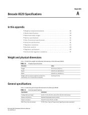
...46 •Environmental regulation compliance 47 Weight and physical dimensions Table 10 lists the weight and physical dimensions of the Brocade 6520. TABLE 11 General specifications Specification Description Configurable port types System architecture System processor ANSI Fibre Channel protocol E_Port, F_Port,...PowerPC family CPU @ 1.20 GHz FC-PH (Fibre Channel Physical and Signalling Interface standard) Brocade 6520 Hardware Reference Manual 39 53-1002705-01 EX_Port with two power supplies and three fan assemblies, but no transceivers installed) 86.74 mm (3.415 in.) 609.75...
...46 •Environmental regulation compliance 47 Weight and physical dimensions Table 10 lists the weight and physical dimensions of the Brocade 6520. TABLE 11 General specifications Specification Description Configurable port types System architecture System processor ANSI Fibre Channel protocol E_Port, F_Port,...PowerPC family CPU @ 1.20 GHz FC-PH (Fibre Channel Physical and Signalling Interface standard) Brocade 6520 Hardware Reference Manual 39 53-1002705-01 EX_Port with two power supplies and three fan assemblies, but no transceivers installed) 86.74 mm (3.415 in.) 609.75...


