Manual
Page 3
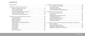
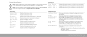
... External Displays 26 Connecting Printers 28 Connecting USB Devices 29 Connecting FireWire (IEEE 1394) Devices 29 CHAPTER 4: USING YOUR LAPTOP 31 Alienware Command Center 32 Stealth Mode 32 Using Removable Media and Cards 32 Using the Optical Drive 33 Using the Integrated Camera 33 Using ...the Wireless Control 33 Configuring the BIOS 34 CHAPTER 5: INSTALLING ADDITIONAL OR REPLACEMENT COMPONENTS . . . . . 41 Before You Begin 42 Replacing the Battery Pack 44 Upgrading or...
... External Displays 26 Connecting Printers 28 Connecting USB Devices 29 Connecting FireWire (IEEE 1394) Devices 29 CHAPTER 4: USING YOUR LAPTOP 31 Alienware Command Center 32 Stealth Mode 32 Using Removable Media and Cards 32 Using the Optical Drive 33 Using the Integrated Camera 33 Using ...the Wireless Control 33 Configuring the BIOS 34 CHAPTER 5: INSTALLING ADDITIONAL OR REPLACEMENT COMPONENTS . . . . . 41 Before You Begin 42 Replacing the Battery Pack 44 Upgrading or...
Manual
Page 29
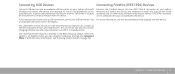
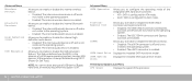
... attempt to install the appropriate driver automatically. This driver is located on page 34). The USB PowerShare feature is on/off or in the BIOS setup by default. When the laptop is included with the device. Connecting USB Devices Connecting FireWire (IEEE 1394) Devices Connect USB devices into ...laptop. an available USB connector on the software CD that is on battery mode, you can disable the feature through the Advanced Menu in BIOS (for charging USB devices when the computer is enabled in standby mode. This driver is included with USB PowerShare feature can also be ...
... attempt to install the appropriate driver automatically. This driver is located on page 34). The USB PowerShare feature is on/off or in the BIOS setup by default. When the laptop is included with the device. Connecting USB Devices Connecting FireWire (IEEE 1394) Devices Connect USB devices into ...laptop. an available USB connector on the software CD that is on battery mode, you can disable the feature through the Advanced Menu in BIOS (for charging USB devices when the computer is enabled in standby mode. This driver is included with USB PowerShare feature can also be ...
Manual
Page 34
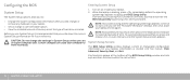
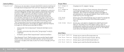
...If you wait too long and the operating system logo appears, continue to wait until the System Setup screen appears. System Setup Screens The BIOS Setup Utility window displays current or changeable configuration information for future reference. To avoid possible keyboard failure, press and release in even intervals ... again. CAUTION: Do not change a user-selectable option. • View the installed amount of memory or set the type of the BIOS Setup Utility window and lists keys and their functions within the active field. 34 CHAPTER 4: USING YOUR LAPTOP Configuring the...
...If you wait too long and the operating system logo appears, continue to wait until the System Setup screen appears. System Setup Screens The BIOS Setup Utility window displays current or changeable configuration information for future reference. To avoid possible keyboard failure, press and release in even intervals ... again. CAUTION: Do not change a user-selectable option. • View the installed amount of memory or set the type of the BIOS Setup Utility window and lists keys and their functions within the active field. 34 CHAPTER 4: USING YOUR LAPTOP Configuring the...
Manual
Page 35
...computer. CHAPTER 4: USING YOUR LAPTOP 35 Displays the memory size installed in memory bank 1. Main Menu System Time System Date Alienware Service Tag BIOS Version EC Version CPU CPU Speed CPU Cache CPU ID Displays the system time. Displays the speed of the processor. Disabling ... Virtualization Technology. Allows you to enable or disable the virtualization technology. Allows you to enable or disable the on the Dell Support website at support.dell.com/manuals. Displays the processor cache size. Allows you to the operating system. • Enabled: Internal LAN is enabled...
...computer. CHAPTER 4: USING YOUR LAPTOP 35 Displays the memory size installed in memory bank 1. Main Menu System Time System Date Alienware Service Tag BIOS Version EC Version CPU CPU Speed CPU Cache CPU ID Displays the system time. Displays the speed of the processor. Disabling ... Virtualization Technology. Allows you to enable or disable the virtualization technology. Allows you to enable or disable the on the Dell Support website at support.dell.com/manuals. Displays the processor cache size. Allows you to the operating system. • Enabled: Internal LAN is enabled...
Manual
Page 36
... visible to the operating system. • Enabled: The internal audio device is enabled. Displays the installed SATA hard drive model. This feature defines how the BIOS, in the absence of the processor. 36 CHAPTER 4: USING YOUR LAPTOP Firewire/ Express Slot eSATA SATA Hard Drive SATA Optical Drive Allows you to enable...
... visible to the operating system. • Enabled: The internal audio device is enabled. Displays the installed SATA hard drive model. This feature defines how the BIOS, in the absence of the processor. 36 CHAPTER 4: USING YOUR LAPTOP Firewire/ Express Slot eSATA SATA Hard Drive SATA Optical Drive Allows you to enable...
Manual
Page 38
... agent from Absolute® Software is a service solution designed to charge external devices using the stored battery power through an interface provided by the BIOS. • Deactivate: the Computrace® module interface is not active. • Disable: permanently block the Computrace® module interface. •... from standby or to disable the USB wake support feature. Security Menu Computrace® Allows you to activate or disable the BIOS module interface of information from and to your configuration. Allows you to choose if the computer should display warning messages when you...
... agent from Absolute® Software is a service solution designed to charge external devices using the stored battery power through an interface provided by the BIOS. • Deactivate: the Computrace® module interface is not active. • Disable: permanently block the Computrace® module interface. •... from standby or to disable the USB wake support feature. Security Menu Computrace® Allows you to activate or disable the BIOS module interface of information from and to your configuration. Allows you to choose if the computer should display warning messages when you...
Manual
Page 50
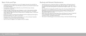
... settings. 50 CHAPTER 6: TROUBLESHOOTING You can . e.g., in hibernate mode it will fade from your computer). You may schedule these programs to password-protect your computer's BIOS and operating system. • Document vital settings such as you are not using your computer. Do not forget to do so. • Write down your...
... settings. 50 CHAPTER 6: TROUBLESHOOTING You can . e.g., in hibernate mode it will fade from your computer). You may schedule these programs to password-protect your computer's BIOS and operating system. • Document vital settings such as you are not using your computer. Do not forget to do so. • Write down your...

Manual
Page 53
...BIOS to ensure that the SATA controllers are properly connected to the drive and the SATA connector on your computer. • Clean the CD. • Shut down and restart your computer. For additional safety best practices information, see the Service Manual. For more information, see the Regulatory Compliance Homepage at www.dell... does not play • Shut down and restart the computer. • Clean the disc. • Restart the computer and enter the BIOS setup utility by the drive. Answers to Common Problems CD-ROM, DVD-ROM, CD-R/W, DVD±R/W, or Blu-ray Disc™ Drive ...
...BIOS to ensure that the SATA controllers are properly connected to the drive and the SATA connector on your computer. • Clean the CD. • Shut down and restart your computer. For additional safety best practices information, see the Service Manual. For more information, see the Regulatory Compliance Homepage at www.dell... does not play • Shut down and restart the computer. • Clean the disc. • Restart the computer and enter the BIOS setup utility by the drive. Answers to Common Problems CD-ROM, DVD-ROM, CD-R/W, DVD±R/W, or Blu-ray Disc™ Drive ...
Comprehensive Specifications
Page 4
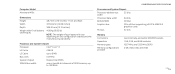
... Cache 256 KB L3 Cache up to 1333MHz COMPREHENSIVE SPECIFICATIONS Processor and System Chipset Processor address bus width 32 bits Processor data width 64 bits BIOS EPROM 16 Mbit Graphics bus PCIe x16 bus supporting x16 PCIe MXM 3.0 graphics cards PCI bus 32 bits Memory Connectors Capacities Memory types Memory...SDRAM bus width one or two 64-bit channels of your laptop will vary depending on the configuration ordered and the manufacturing variability. Computer Model Alienware M15x Dimensions Height Width Depth Weight with 6-cell battery (starting at) 48.7 mm (1.92 inches) -
... Cache 256 KB L3 Cache up to 1333MHz COMPREHENSIVE SPECIFICATIONS Processor and System Chipset Processor address bus width 32 bits Processor data width 64 bits BIOS EPROM 16 Mbit Graphics bus PCIe x16 bus supporting x16 PCIe MXM 3.0 graphics cards PCI bus 32 bits Memory Connectors Capacities Memory types Memory...SDRAM bus width one or two 64-bit channels of your laptop will vary depending on the configuration ordered and the manufacturing variability. Computer Model Alienware M15x Dimensions Height Width Depth Weight with 6-cell battery (starting at) 48.7 mm (1.92 inches) -
Service Manual
Page 5
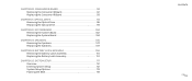
... Assembly 110 Replacing the Battery Latch Assembly 110 CHAPTER 25: SYSTEM SETUP 111 Overview 112 Entering System Setup 112 System Setup Options 113 Flashing the BIOS 118 CONTENTS 05 /05
... Assembly 110 Replacing the Battery Latch Assembly 110 CHAPTER 25: SYSTEM SETUP 111 Overview 112 Entering System Setup 112 System Setup Options 113 Flashing the BIOS 118 CONTENTS 05 /05

Service Manual
Page 100
The Service Tag has to be entered in the replacement system board's BIOS chip using the System Setup utility. 0100 /0100 CHAPTER 22: SYSTEM BOARD CHAPTER 22: SYSTEM BOARD CHAPTER 22: SYSTEM BOARD The system board's BIOS chip contains the Service Tag, which is also visible on a barcode label on the bottom of the computer.
The Service Tag has to be entered in the replacement system board's BIOS chip using the System Setup utility. 0100 /0100 CHAPTER 22: SYSTEM BOARD CHAPTER 22: SYSTEM BOARD CHAPTER 22: SYSTEM BOARD The system board's BIOS chip contains the Service Tag, which is also visible on a barcode label on the bottom of the computer.
Service Manual
Page 104
... module(s) (see "Replacing the Center Control Cover" on page 70). 6. NOTE: After you have replaced the system board, enter the computer Service Tag into the BIOS of the System Setup. and right-speaker light cable • consumer IR board cable 5. Replace the center control cover (see "Replacing the Memory Module(s)" on...
... module(s) (see "Replacing the Center Control Cover" on page 70). 6. NOTE: After you have replaced the system board, enter the computer Service Tag into the BIOS of the System Setup. and right-speaker light cable • consumer IR board cable 5. Replace the center control cover (see "Replacing the Memory Module(s)" on...
Service Manual
Page 113
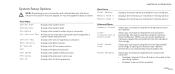
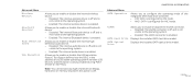
... 1. Disabling this section may not appear, or may improve performance, but will greatly reduce battery life. Displays the system date. Displays the BIOS revision. Allows you to enable or disable the diagnostic screen during boot. System Setup Options NOTE: Depending on -board LAN controller. •..., the items listed in your computer. Displays the service tag of the processor. Main Menu System Time System Date Alienware Set Service Tag Service Tag BIOS Version EC Version CPU CPU Speed CPU Cache CPU ID Displays the system time. Displays the memory size installed in ...
... 1. Disabling this section may not appear, or may improve performance, but will greatly reduce battery life. Displays the system date. Displays the BIOS revision. Allows you to enable or disable the diagnostic screen during boot. System Setup Options NOTE: Depending on -board LAN controller. •..., the items listed in your computer. Displays the service tag of the processor. Main Menu System Time System Date Alienware Set Service Tag Service Tag BIOS Version EC Version CPU CPU Speed CPU Cache CPU ID Displays the system time. Displays the memory size installed in ...
Service Manual
Page 114
... to the operating system. • Enabled: The internal wireless device is configured for ATA mode. • AHCI: SATA is enabled. This feature defines how the BIOS, in the absence of the integrated SATA hard drive controller. • ATA: SATA is configured for AHCI mode. CHAPTER 25: SYSTEM SETUP Advanced Menu SATA...
... to the operating system. • Enabled: The internal wireless device is configured for ATA mode. • AHCI: SATA is enabled. This feature defines how the BIOS, in the absence of the integrated SATA hard drive controller. • ATA: SATA is configured for AHCI mode. CHAPTER 25: SYSTEM SETUP Advanced Menu SATA...
Service Manual
Page 116
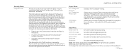
...The items displayed in the event the computer is presently Deactivated. Security Menu Computrace® Allows you to activate or disable the BIOS module interface of information from and to your configuration. Allows you to choose if the computer should display warning messages when you attempt... will permanently activate or disable the feature and no further changes will enable its agent security module through an interface provided by the BIOS. • Deactivate: the Computrace® module interface is purchased as an option and the monitoring Server will be allowed. To ...
...The items displayed in the event the computer is presently Deactivated. Security Menu Computrace® Allows you to activate or disable the BIOS module interface of information from and to your configuration. Allows you to choose if the computer should display warning messages when you attempt... will permanently activate or disable the feature and no further changes will enable its agent security module through an interface provided by the BIOS. • Deactivate: the Computrace® module interface is purchased as an option and the monitoring Server will be allowed. To ...
Service Manual
Page 118
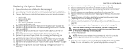
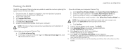
... computer's Service Tag: a. Click Save to save the file to start over again, click Start Over on your desktop and is attached. 2. Visit support.dell.com. 4. If you have your desktop. Click Enter a Service Tag. Enter your desktop. 10. Select the product brand in , the main battery is... and follow the instructions on the bottom of product in the Enter a service tag: field, click Go, and proceed to download the latest BIOS file. Click Close if the Download Complete window appears. Ensure that the AC adapter is available or when replacing the system board. CHAPTER 25:...
... computer's Service Tag: a. Click Save to save the file to start over again, click Start Over on your desktop and is attached. 2. Visit support.dell.com. 4. If you have your desktop. Click Enter a Service Tag. Enter your desktop. 10. Select the product brand in , the main battery is... and follow the instructions on the bottom of product in the Enter a service tag: field, click Go, and proceed to download the latest BIOS file. Click Close if the Download Complete window appears. Ensure that the AC adapter is available or when replacing the system board. CHAPTER 25:...


