
Manual
Page 3
...16 Display Features 17 Computer Base and Keyboard Features 18 Status Lights 19 Touch Controls 19 Power Button 20 Function Keys 21 Battery Pack 22 Power Management 23 CHAPTER 3: CONNECTING DEVICES 25 Connecting External Displays 26 Connecting Printers 28 Connecting USB Devices 29 Connecting FireWire (IEEE 1394) Devices 29 CHAPTER 4: USING YOUR LAPTOP 31 Alienware Command Center 32 Stealth Mode 32 Using Removable Media and Cards 32 Using the Optical Drive 33 Using the Integrated Camera 33 Using the Wireless Control 33 Configuring the BIOS 34 CHAPTER 5: INSTALLING ADDITIONAL...
...16 Display Features 17 Computer Base and Keyboard Features 18 Status Lights 19 Touch Controls 19 Power Button 20 Function Keys 21 Battery Pack 22 Power Management 23 CHAPTER 3: CONNECTING DEVICES 25 Connecting External Displays 26 Connecting Printers 28 Connecting USB Devices 29 Connecting FireWire (IEEE 1394) Devices 29 CHAPTER 4: USING YOUR LAPTOP 31 Alienware Command Center 32 Stealth Mode 32 Using Removable Media and Cards 32 Using the Optical Drive 33 Using the Integrated Camera 33 Using the Wireless Control 33 Configuring the BIOS 34 CHAPTER 5: INSTALLING ADDITIONAL...
Manual
Page 8
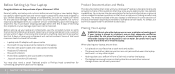
... Documentation and Media The documentation that ships with power cable and video cable (if ordered) • Keyboard (if ordered) • Mouse (if ordered) • Multimedia speakers and sub-woofer (if ordered) • Joystick controllers (if ordered) You may also need a small flathead and/or a Phillips head screwdriver for connecting peripheral cables to inspect all safety and setup instructions before connecting your Alienware® M15x! As always, our technical support staff is provided...
... Documentation and Media The documentation that ships with power cable and video cable (if ordered) • Keyboard (if ordered) • Mouse (if ordered) • Multimedia speakers and sub-woofer (if ordered) • Joystick controllers (if ordered) You may also need a small flathead and/or a Phillips head screwdriver for connecting peripheral cables to inspect all safety and setup instructions before connecting your Alienware® M15x! As always, our technical support staff is provided...

Manual
Page 10
... telephone service for setup instructions. To complete setting up your Internet connection. • If you are using a dial-up connection, connect the telephone line to the optional external USB modem and to the Internet (Optional) Setting Up a Wired Connection • If you requested while ordering your computer unusable. Doing so may render your computer. Connect the Network Cable (Optional) 10 CHAPTER 1: SETTING UP YOUR LAPTOP Set Up Microsoft Windows CAUTION: Do not interrupt the operating system's setup...
... telephone service for setup instructions. To complete setting up your Internet connection. • If you are using a dial-up connection, connect the telephone line to the optional external USB modem and to the Internet (Optional) Setting Up a Wired Connection • If you requested while ordering your computer unusable. Doing so may render your computer. Connect the Network Cable (Optional) 10 CHAPTER 1: SETTING UP YOUR LAPTOP Set Up Microsoft Windows CAUTION: Do not interrupt the operating system's setup...

Manual
Page 23
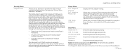
...did not use . Why? CHAPTER 2: GETTING TO KNOW YOUR LAPTOP 23 The battery then needs to be a good idea for a few days. Power Management Understanding Power Consumption In order to bring the battery voltage level high enough) before use my spare battery for months. Saves power on your ...your activity and by your battery, it would be pre-charged (to fully utilize the power of the power management concept from your operating system. Always keep the battery inside the laptop and have the AC adapter connected whenever possible. Fast charge usually takes 2-3 hours. Pre-charge may ...
...did not use . Why? CHAPTER 2: GETTING TO KNOW YOUR LAPTOP 23 The battery then needs to be a good idea for a few days. Power Management Understanding Power Consumption In order to bring the battery voltage level high enough) before use my spare battery for months. Saves power on your ...your activity and by your battery, it would be pre-charged (to fully utilize the power of the power management concept from your operating system. Always keep the battery inside the laptop and have the AC adapter connected whenever possible. Fast charge usually takes 2-3 hours. Pre-charge may ...
Manual
Page 28
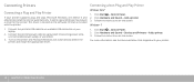
... CHAPTER 3: CONNECTING DEVICES Click Start → Control Panel. 2. Click Hardware and Sound→ Add a printer. 3. Click Hardware and Sound→ Devices and Printers→ Add a printer. 3. For more information, see the documentation that is located on the screen. In some cases, Windows may require a driver for the printer. Follow the instructions on the software CD that shipped with the printer. 1. Connect the printer's USB cable to an available USB connector...
... CHAPTER 3: CONNECTING DEVICES Click Start → Control Panel. 2. Click Hardware and Sound→ Add a printer. 3. Click Hardware and Sound→ Devices and Printers→ Add a printer. 3. For more information, see the documentation that is located on the screen. In some cases, Windows may require a driver for the printer. Follow the instructions on the software CD that shipped with the printer. 1. Connect the printer's USB cable to an available USB connector...
Manual
Page 29
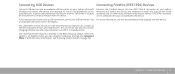
... the device. The USB PowerShare feature is on battery mode, you can disable the feature through the Advanced Menu in BIOS (for charging USB devices when the computer is included with the device. In some cases, Windows may require a driver. This driver is located on the software CD that is included with USB PowerShare feature can also be used for more information, see "Entering System Setup" on the laptop. This driver is located...
... the device. The USB PowerShare feature is on battery mode, you can disable the feature through the Advanced Menu in BIOS (for charging USB devices when the computer is included with the device. In some cases, Windows may require a driver. This driver is located on the software CD that is included with USB PowerShare feature can also be used for more information, see "Entering System Setup" on the laptop. This driver is located...
Manual
Page 36
... Express Card slot are off and is not visible to the operating system. • Enabled: The internal audio device is enabled. Advanced Menu SATA Operation Allows you to enable or disable the USB emulation feature. Displays the installed SATA optical drive model. Allows you to configure the operating mode of USB device (floppy, hard drive, or memory key) when this option is off and is not visible to the operating system. • Enabled: The internal wireless device is enabled. Advanced Menu Wireless Network Bluetooth Receiver High Definition Sound USB...
... Express Card slot are off and is not visible to the operating system. • Enabled: The internal audio device is enabled. Advanced Menu SATA Operation Allows you to enable or disable the USB emulation feature. Displays the installed SATA optical drive model. Allows you to configure the operating mode of USB device (floppy, hard drive, or memory key) when this option is off and is not visible to the operating system. • Enabled: The internal wireless device is enabled. Advanced Menu Wireless Network Bluetooth Receiver High Definition Sound USB...
Manual
Page 37
... 4: USING YOUR LAPTOP 37 Select Clock Mode Allows you to enter the memory voltage. The supervisor password controls access to the computer at boot. Displays the asset tag. Memory Frequency • Auto • Unlinked Allows you to enable or disable password entry on Boot Asset Tag Displays if the supervisor password is set the supervisor password. DDR3 Voltage Allows you to set . The user password controls access to the system setup utility. Allows you to set . Performance Options...
... 4: USING YOUR LAPTOP 37 Select Clock Mode Allows you to enter the memory voltage. The supervisor password controls access to the computer at boot. Displays the asset tag. Memory Frequency • Auto • Unlinked Allows you to enable or disable password entry on Boot Asset Tag Displays if the supervisor password is set the supervisor password. DDR3 Voltage Allows you to set . The user password controls access to the system setup utility. Allows you to set . Performance Options...
Manual
Page 38
... computer displays these messages if you to set the fourth boot device. 38 CHAPTER 4: USING YOUR LAPTOP Allows you attempt to use certain power adapters. The Computrace® agent from Absolute® Software is a service solution designed to charge external devices using the stored battery power through an interface provided by the BIOS. • Deactivate: the Computrace® module interface is presently Deactivated. Security Menu Computrace® Allows you to enable USB devices...
... computer displays these messages if you to set the fourth boot device. 38 CHAPTER 4: USING YOUR LAPTOP Allows you attempt to use certain power adapters. The Computrace® agent from Absolute® Software is a service solution designed to charge external devices using the stored battery power through an interface provided by the BIOS. • Deactivate: the Computrace® module interface is presently Deactivated. Security Menu Computrace® Allows you to enable USB devices...

Manual
Page 46
... boot. Use your fingertips to the tab on the memory module to carefully spread apart the memory module connector's spring-locks until the module pops up. 5. While inserting the memory module into the connector align the notch on the memory module connector. NOTE: Install the memory module first in the bottom connector and then in reverse order. 3. Remove the memory module. 46 CHAPTER 5: INSTALLING ADDITIONAL OR REPLACEMENT COMPONENTS 5 4 1 memory module connector 2 notch 3 tab 4 spring locks (2) 5 memory module...
... boot. Use your fingertips to the tab on the memory module to carefully spread apart the memory module connector's spring-locks until the module pops up. 5. While inserting the memory module into the connector align the notch on the memory module connector. NOTE: Install the memory module first in the bottom connector and then in reverse order. 3. Remove the memory module. 46 CHAPTER 5: INSTALLING ADDITIONAL OR REPLACEMENT COMPONENTS 5 4 1 memory module connector 2 notch 3 tab 4 spring locks (2) 5 memory module...
Manual
Page 57
... battery charge may be installed in a power saving mode: Press a key on page 73). Test the electrical outlet: Ensure that the light is recommended that memory modules be in pairs. Check the AC adapter: Check the AC adapter cable connections and ensure that the electrical outlet is working by testing it is on. Display If the display is attached to an external monitor, press to switch the video image to power...
... battery charge may be installed in a power saving mode: Press a key on page 73). Test the electrical outlet: Ensure that the light is recommended that memory modules be in pairs. Check the AC adapter: Check the AC adapter cable connections and ensure that the electrical outlet is working by testing it is on. Display If the display is attached to an external monitor, press to switch the video image to power...
Manual
Page 58
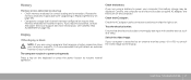
... external monitor works, the computer display or video controller may be replaced. • Restart your computer. • Try a mouse that you know works in the same connector, to ensure that the USB connector is working • Check if the mouse cable is properly connected to the USB connector on your computer and connect an external monitor to decrease brightness. If the mouse cable is damaged. Adjust the Windows display settings: Windows Vista® 1. Click Start → Control Panel→ Hardware and Software...
... external monitor works, the computer display or video controller may be replaced. • Restart your computer. • Try a mouse that you know works in the same connector, to ensure that the USB connector is working • Check if the mouse cable is properly connected to the USB connector on your computer and connect an external monitor to decrease brightness. If the mouse cable is damaged. Adjust the Windows display settings: Windows Vista® 1. Click Start → Control Panel→ Hardware and Software...
Manual
Page 62
... option is on page 73). It allows recovery through System Restore even if Windows cannot be accessed and resolves many software-related problems, including operating system configuration errors, driver installation errors, system file corruption, spyware/virus infection (when used in Windows, restart). 3. Although System Restore will display a prompt on your optical drive. 2. Backup functionality is included in AlienRespawn v2.0, but as a precaution it is recommended to backup critical files onto an external media...
... option is on page 73). It allows recovery through System Restore even if Windows cannot be accessed and resolves many software-related problems, including operating system configuration errors, driver installation errors, system file corruption, spyware/virus infection (when used in Windows, restart). 3. Although System Restore will display a prompt on your optical drive. 2. Backup functionality is included in AlienRespawn v2.0, but as a precaution it is recommended to backup critical files onto an external media...
Manual
Page 63
... optional AlienRespawn v2.0 disc as shipped. Password Protection Since AlienRespawn v2.0 has the ability to its factory default state, resolving all desired files, this reason, it ; Once you have retrieved all software/ configuration issues. In cases of it is disabled by booting to recover your preferred third-party antivirus/antispyware utilities prior to its original factory configuration resolving all external storage media to permanent locations. Alienware Technical Support...
... optional AlienRespawn v2.0 disc as shipped. Password Protection Since AlienRespawn v2.0 has the ability to its factory default state, resolving all desired files, this reason, it ; Once you have retrieved all software/ configuration issues. In cases of it is disabled by booting to recover your preferred third-party antivirus/antispyware utilities prior to its original factory configuration resolving all external storage media to permanent locations. Alienware Technical Support...

Service Manual
Page 18
... "Replacing the Battery Pack" on page 6. 2. Install the drivers and utilities for your computer, as needed . 11. If you use excessive force, you may result in "Before You Begin" on page 11). Replace the four screws that no stray screws remain inside the computer. Install the operating system for storing or shipping the hard drive. Remove the new drive from the hard drive. 2 1 1 interposer 2 hard drive CHAPTER 4: HARD DRIVE Replacing the Hard Drive 1. Failure...
... "Replacing the Battery Pack" on page 6. 2. Install the drivers and utilities for your computer, as needed . 11. If you use excessive force, you may result in "Before You Begin" on page 11). Replace the four screws that no stray screws remain inside the computer. Install the operating system for storing or shipping the hard drive. Remove the new drive from the hard drive. 2 1 1 interposer 2 hard drive CHAPTER 4: HARD DRIVE Replacing the Hard Drive 1. Failure...

Service Manual
Page 19
... two user-accessible SODIMM sockets that are covered under your Mobile Manual or in the Comprehensive Specifications at support.dell.com/manuals for information on the system board. NOTE: Memory modules purchased from the bottom of the computer. 019 /019 CHAPTER 5: MEMORY MODULE(S) CHAPTER 5: MEMORY MODULE(S) CHAPTER 5: MEMORY MODULE(S) You can be accessed from Dell or Alienware are supported by your computer. Install only memory modules that can increase your computer memory by installing memory modules on the memory supported...
... two user-accessible SODIMM sockets that are covered under your Mobile Manual or in the Comprehensive Specifications at support.dell.com/manuals for information on the system board. NOTE: Memory modules purchased from the bottom of the computer. 019 /019 CHAPTER 5: MEMORY MODULE(S) CHAPTER 5: MEMORY MODULE(S) CHAPTER 5: MEMORY MODULE(S) You can be accessed from Dell or Alienware are supported by your computer. Install only memory modules that can increase your computer memory by installing memory modules on the memory supported...

Service Manual
Page 23
... memory module is difficult to close may not boot. 023 /023 Follow the instructions in "Before You Begin" on the memory-module connector. 3. Replacing the Memory Module(s) CAUTION: If you need to install memory modules in two connectors, install a memory module in the lower connector before you do not hear the click, remove the module and reinstall it. 2 4 3 2 CHAPTER 5: MEMORY MODULE(S) 1 1 1 memory module 2 memory-module connector 3 tab 4 notch CAUTION: If the memory-module door is not installed...
... memory module is difficult to close may not boot. 023 /023 Follow the instructions in "Before You Begin" on the memory-module connector. 3. Replacing the Memory Module(s) CAUTION: If you need to install memory modules in two connectors, install a memory module in the lower connector before you do not hear the click, remove the module and reinstall it. 2 4 3 2 CHAPTER 5: MEMORY MODULE(S) 1 1 1 memory module 2 memory-module connector 3 tab 4 notch CAUTION: If the memory-module door is not installed...

Service Manual
Page 30
...). 4. Turn the center control cover as possible. 1 center control cover 030 /030 Turn the computer top side up with the cable that attaches it to the system board connector are very fragile. 8. Remove the compartment door (see "Removing the Memory Module(s)" on page 6. 2. CHAPTER 7: CENTER CONTROL COVER CAUTION: Be extremely careful when removing the center control cover. Remove the battery pack (see "Removing the Hard Drive" on page 11). 3. Remove the hard drive (see "Removing the Battery...
...). 4. Turn the center control cover as possible. 1 center control cover 030 /030 Turn the computer top side up with the cable that attaches it to the system board connector are very fragile. 8. Remove the compartment door (see "Removing the Memory Module(s)" on page 6. 2. CHAPTER 7: CENTER CONTROL COVER CAUTION: Be extremely careful when removing the center control cover. Remove the battery pack (see "Removing the Hard Drive" on page 11). 3. Remove the hard drive (see "Removing the Battery...

Service Manual
Page 49
... board connector. NOTE: If you are installing. 7. Replacing the Full Mini-Card 1. If you use excessive force, you must install the appropriate drivers and utilities. 049 /049 Press the other than Dell or Alienware, you may result in "Before You Begin" on the connector. 4. Connect the blue antenna cable to slide the card into the slot on page 39). Replace the palm rest (see "Replacing the Battery...
... board connector. NOTE: If you are installing. 7. Replacing the Full Mini-Card 1. If you use excessive force, you must install the appropriate drivers and utilities. 049 /049 Press the other than Dell or Alienware, you may result in "Before You Begin" on the connector. 4. Connect the blue antenna cable to slide the card into the slot on page 39). Replace the palm rest (see "Replacing the Battery...
Service Manual
Page 116
... devices detected. Power Menu A/C Adapter Rating A/C Adapter Warnings USB Wake Support CHAPTER 25: SYSTEM SETUP Displays the AC adapter rating. Boot Menu Hard Drive Sets the hard drive boot priority. Security Menu Computrace® Allows you to enable USB devices to wake the computer from standby or to disable the USB wake support feature. Allows you to activate or disable the BIOS module interface of information from and to provide the tracking service. CD\DVD\BD-ROM Sets the optical drive boot priority. To change the boot order...
... devices detected. Power Menu A/C Adapter Rating A/C Adapter Warnings USB Wake Support CHAPTER 25: SYSTEM SETUP Displays the AC adapter rating. Boot Menu Hard Drive Sets the hard drive boot priority. Security Menu Computrace® Allows you to enable USB devices to wake the computer from standby or to disable the USB wake support feature. Allows you to activate or disable the BIOS module interface of information from and to provide the tracking service. CD\DVD\BD-ROM Sets the optical drive boot priority. To change the boot order...


