

Service Manual
Page 1
... loss of data and tells you make better use of Intel Corporation; Bluetooth is subject to change without the written permission of Dell Inc.; CAUTION: A CAUTION indicates a potential for I/O Connectors Notes, Notices, and Cautions NOTE: A NOTE indicates important information that... helps you how to avoid the problem. under license. All rights reserved. Intel is strictly forbidden. Dell Inc. Dell™ Latitude™ D610 Service Manual Before You Begin System Components Internal Card With Bluetooth® Wireless Technology Hard Drive ...
... loss of data and tells you make better use of Intel Corporation; Bluetooth is subject to change without the written permission of Dell Inc.; CAUTION: A CAUTION indicates a potential for I/O Connectors Notes, Notices, and Cautions NOTE: A NOTE indicates important information that... helps you how to avoid the problem. under license. All rights reserved. Intel is strictly forbidden. Dell Inc. Dell™ Latitude™ D610 Service Manual Before You Begin System Components Internal Card With Bluetooth® Wireless Technology Hard Drive ...
Service Manual
Page 2
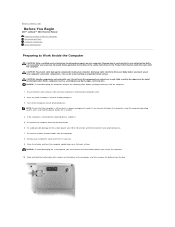
...work surface is connected to a docking device, undock it. 5. NOTE: Ensure that came with care. Hold a card by its edges or by Dell is off the computer and all attached devices. Turn off and not in a power management mode. NOTICE: To avoid damaging the system board, you... must remove the main battery before you cannot shut down on a card. Back to Contents Page Before You Begin Dell™ Latitude™ D610 Service Manual Preparing to Work Inside the Computer Recommended Tools Computer Orientation Screw Identification Preparing to Work Inside the ...
...work surface is connected to a docking device, undock it. 5. NOTE: Ensure that came with care. Hold a card by its edges or by Dell is off the computer and all attached devices. Turn off and not in a power management mode. NOTICE: To avoid damaging the system board, you... must remove the main battery before you cannot shut down on a card. Back to Contents Page Before You Begin Dell™ Latitude™ D610 Service Manual Preparing to Work Inside the Computer Recommended Tools Computer Orientation Screw Identification Preparing to Work Inside the ...
Service Manual
Page 3
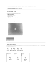
Remove any installed memory modules, Mini PCI cards, and devices, including a second battery if one is installed. 12. Remove the hard drive (see "Removing the Hard Drive"). Recommended Tools The procedures in this manual require the following tools: l #1 Phillips screwdriver l ¼-inch flat-blade screwdriver l Small plastic scribe l Flash BIOS update program floppy or CD Computer Orientation 1 back 2 right 3 front 4 left Screw Identification When you are removing and replacing components, photocopy "Screw Identification" as a tool to lay out and keep track of screws and ...
Remove any installed memory modules, Mini PCI cards, and devices, including a second battery if one is installed. 12. Remove the hard drive (see "Removing the Hard Drive"). Recommended Tools The procedures in this manual require the following tools: l #1 Phillips screwdriver l ¼-inch flat-blade screwdriver l Small plastic scribe l Flash BIOS update program floppy or CD Computer Orientation 1 back 2 right 3 front 4 left Screw Identification When you are removing and replacing components, photocopy "Screw Identification" as a tool to lay out and keep track of screws and ...

Service Manual
Page 4
Display Assembly: (4 each) Display Bezel: (6 each) Display Panel: (4 each) Display Latch: (1 each) Palm Rest: (2 each at top) Fan: (2 each) (13 each at bottom) Speakers: (2 each-1 on each side) Modem: (1 each) System Board: (5 each) Back to Contents Page
Display Assembly: (4 each) Display Bezel: (6 each) Display Panel: (4 each) Display Latch: (1 each) Palm Rest: (2 each at top) Fan: (2 each) (13 each at bottom) Speakers: (2 each-1 on each side) Modem: (1 each) System Board: (5 each) Back to Contents Page
Service Manual
Page 5
... the computer. Press and to boot and updates the new BIOS. Press , select Save changes and reboot, and press to Contents Page Flashing the BIOS Dell™ Latitude™ D610 Service Manual 1. Ensure that the AC adapter is plugged in and that appear on the computer. Back to save configuration changes...
... the computer. Press and to boot and updates the new BIOS. Press , select Save changes and reboot, and press to Contents Page Flashing the BIOS Dell™ Latitude™ D610 Service Manual 1. Ensure that the AC adapter is plugged in and that appear on the computer. Back to save configuration changes...
Service Manual
Page 6
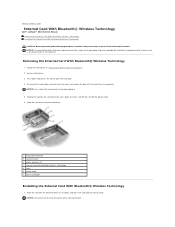
... it. 5. NOTICE: Press down the lever, and lift the card off the plastic knob. 6. Back to Contents Page Internal Card With Bluetooth® Wireless Technology Dell™ Latitude™ D610 Service Manual Removing the Internal Card With Bluetooth® Wireless Technology Installing the Internal Card With Bluetooth® Wireless Technology CAUTION...
... it. 5. NOTICE: Press down the lever, and lift the card off the plastic knob. 6. Back to Contents Page Internal Card With Bluetooth® Wireless Technology Dell™ Latitude™ D610 Service Manual Removing the Internal Card With Bluetooth® Wireless Technology Installing the Internal Card With Bluetooth® Wireless Technology CAUTION...

Service Manual
Page 7
Connect the card to Contents Page Replace the battery. Back to the card cable connector, slide the door with the card into the card compartment, and gently press the door into position. 3. 2.
Connect the card to Contents Page Replace the battery. Back to the card cable connector, slide the door with the card into the card compartment, and gently press the door into position. 3. 2.
Service Manual
Page 8
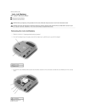
... slide the coin-cell battery out of the securing sleeve. 1 coin-cell battery 2 battery connector on system board Back to Contents Page Coin-Cell Battery Dell™ Latitude™ D610 Service Manual Removing the Coin-Cell Battery Installing the Coin-Cell Battery CAUTION: Before you begin any of your body before...
... slide the coin-cell battery out of the securing sleeve. 1 coin-cell battery 2 battery connector on system board Back to Contents Page Coin-Cell Battery Dell™ Latitude™ D610 Service Manual Removing the Coin-Cell Battery Installing the Coin-Cell Battery CAUTION: Before you begin any of your body before...

Service Manual
Page 9
Slide the battery into the securing sleeve. 3. Replace the modem cover. Connect the coin-cell battery cable connector to Contents Page 3 coin-cell battery cable connector 4 securing sleeve Installing the Coin-Cell Battery 1. Back to the battery connector on the system board. 2.
Slide the battery into the securing sleeve. 3. Replace the modem cover. Connect the coin-cell battery cable connector to Contents Page 3 coin-cell battery cable connector 4 securing sleeve Installing the Coin-Cell Battery 1. Back to the battery connector on the system board. 2.
Service Manual
Page 10
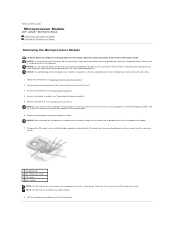
... not to bend the pins on which the die is perpendicular to the microprocessor when turning the cam screw. 1. Back to Contents Page Microprocessor Module Dell™ Latitude™ D610 Service Manual Removing the Microprocessor Module Installing the Microprocessor Module Removing the Microprocessor Module CAUTION: Before you cannot turn the screw...
... not to bend the pins on which the die is perpendicular to the microprocessor when turning the cam screw. 1. Back to Contents Page Microprocessor Module Dell™ Latitude™ D610 Service Manual Removing the Microprocessor Module Installing the Microprocessor Module Removing the Microprocessor Module CAUTION: Before you cannot turn the screw...

Service Manual
Page 11
Seating the microprocessor module properly in the ZIF socket to avoid permanent damage to the module and the socket. NOTICE: You must position the microprocessor module correctly in the ZIF socket does not require force. If one or more corners of the ZIF socket, and insert the microprocessor module. Tighten the ZIF socket by turning the cam screw clockwise until you removed earlier in the fully open position before seating the microprocessor module. For instructions on the pin-1 corner of the microprocessor module has a triangle that is not properly seated can result in an intermittent...
Seating the microprocessor module properly in the ZIF socket to avoid permanent damage to the module and the socket. NOTICE: You must position the microprocessor module correctly in the ZIF socket does not require force. If one or more corners of the ZIF socket, and insert the microprocessor module. Tighten the ZIF socket by turning the cam screw clockwise until you removed earlier in the fully open position before seating the microprocessor module. For instructions on the pin-1 corner of the microprocessor module has a triangle that is not properly seated can result in an intermittent...
Service Manual
Page 12
... heat sink 5 display connector on system board 6 pull-tab on the computer. Follow the instructions in "Preparing to Contents Page Display Assembly and Display Latch Dell™ Latitude™ D610 Service Manual Display Assembly Display Bezel Display Panel Display Latch Display Assembly CAUTION: Before you remove the palm rest. Use the...
... heat sink 5 display connector on system board 6 pull-tab on the computer. Follow the instructions in "Preparing to Contents Page Display Assembly and Display Latch Dell™ Latitude™ D610 Service Manual Display Assembly Display Bezel Display Panel Display Latch Display Assembly CAUTION: Before you remove the palm rest. Use the...
Service Manual
Page 13
Route the two antenna cables under the routing clips. Follow the instructions in the Product Information Guide. Replace the center control cover (see "Removing the Center Control Cover"). 3. Display Bezel CAUTION: Before you route the antenna cables under the routing clips. Use a plastic scribe tool to Work Inside the Computer." 2. Remove the center control cover (see "Installing the Center Control Cover"). Lift the display assembly up and out of the procedures in this section, follow the safety instructions in "Preparing to pry the six display bumpers out ...
Route the two antenna cables under the routing clips. Follow the instructions in the Product Information Guide. Replace the center control cover (see "Removing the Center Control Cover"). 3. Display Bezel CAUTION: Before you route the antenna cables under the routing clips. Use a plastic scribe tool to Work Inside the Computer." 2. Remove the center control cover (see "Installing the Center Control Cover"). Lift the display assembly up and out of the procedures in this section, follow the safety instructions in "Preparing to pry the six display bumpers out ...

Service Manual
Page 14
Starting at any of the display bezel until it snaps completely off. Starting at the bottom of the display panel (by the Dell™ logo), use your fingers to gently snap the bezel in the Product Information Guide. NOTE: Follow the same procedure on the computer. Installing the ...
Starting at any of the display bezel until it snaps completely off. Starting at the bottom of the display panel (by the Dell™ logo), use your fingers to gently snap the bezel in the Product Information Guide. NOTE: Follow the same procedure on the computer. Installing the ...
Service Manual
Page 15
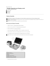
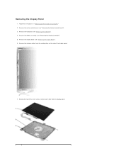
Remove the display assembly (see "Removing the Keyboard"). 4. Removing the Display Panel 1. Follow the instructions in "Preparing to Work Inside the Computer." 2. Remove the keyboard (see "Removing the Display Assembly"). 5. Remove the four M2 x 3-mm screws (two on each side) from the routing clips on the side of the display panel. 7. Remove the display bezel (see "Removing the Center Control Cover"). 3. Remove the center control cover (see "Removing the Display Bezel"). 6. Remove the antenna cables from the display panel.
Remove the display assembly (see "Removing the Keyboard"). 4. Removing the Display Panel 1. Follow the instructions in "Preparing to Work Inside the Computer." 2. Remove the keyboard (see "Removing the Display Assembly"). 5. Remove the four M2 x 3-mm screws (two on each side) from the routing clips on the side of the display panel. 7. Remove the display bezel (see "Removing the Center Control Cover"). 3. Remove the center control cover (see "Removing the Display Bezel"). 6. Remove the antenna cables from the display panel.

Service Manual
Page 16
Follow the instructions in both sides of the top display cable connector, and pull the display cable connector away from the inverter connector. 1 top flex-cable connector 2 top display-cable connector 3 pull-tab on each side) around the display panel. 5. 1 display panel 2 top cover 3 M2 x 3-mm screws (4) 8. Use the pull-tab to disconnect the bottom flex-cable connector from the top flex-cable connector. Installing the Display Panel 1. Tighten the four M2 x 3-mm screws (two on bottom flex-cable connector 10. Display Latch NOTICE: Disconnect the computer and any ...
Follow the instructions in both sides of the top display cable connector, and pull the display cable connector away from the inverter connector. 1 top flex-cable connector 2 top display-cable connector 3 pull-tab on each side) around the display panel. 5. 1 display panel 2 top cover 3 M2 x 3-mm screws (4) 8. Use the pull-tab to disconnect the bottom flex-cable connector from the top flex-cable connector. Installing the Display Panel 1. Tighten the four M2 x 3-mm screws (two on bottom flex-cable connector 10. Display Latch NOTICE: Disconnect the computer and any ...

Service Manual
Page 17
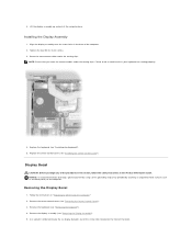
Align the latch on the guide pins located on the top cover. 2. Back to the top cover. Remove the display latch (see "Removing the Display Latch"). 1 M2.5 x 5-mm screw 2 display latch 3 guide pins (2) 4 top cover Installing the Display Latch 1. Insert and tighten the M2.5 x 5-mm screw that secures the display latch to Contents Page 7.
Align the latch on the guide pins located on the top cover. 2. Back to the top cover. Remove the display latch (see "Removing the Display Latch"). 1 M2.5 x 5-mm screw 2 display latch 3 guide pins (2) 4 top cover Installing the Display Latch 1. Insert and tighten the M2.5 x 5-mm screw that secures the display latch to Contents Page 7.
Service Manual
Page 18
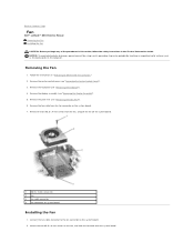
... "Removing the Display Assembly"). 5. Connect the fan cable connector to the fan connector on the computer. Follow the instructions in "Preparing to Contents Page Fan Dell™ Latitude™ D610 Service Manual Removing the Fan Installing the Fan CAUTION: Before you begin any of the procedures in this section, follow the...
... "Removing the Display Assembly"). 5. Connect the fan cable connector to the fan connector on the computer. Follow the instructions in "Preparing to Contents Page Fan Dell™ Latitude™ D610 Service Manual Removing the Fan Installing the Fan CAUTION: Before you begin any of the procedures in this section, follow the...
Service Manual
Page 20
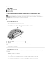
... Use firm and even pressure to slide the drive into the bay until it in hibernate mode. Back to Contents Page Hard Drive Dell™ Latitude™ D610 Service Manual Removing the Hard Drive Installing the Hard Drive CAUTION: If you remove the hard drive from ...sources other than Dell. CAUTION: Before you may damage the connector. 1. NOTICE: To prevent data loss, shut down your User's Guide. 4. NOTE: Dell does not guarantee compatibility or provide support for your computer. mm screws. 1 M3 x ...
... Use firm and even pressure to slide the drive into the bay until it in hibernate mode. Back to Contents Page Hard Drive Dell™ Latitude™ D610 Service Manual Removing the Hard Drive Installing the Hard Drive CAUTION: If you remove the hard drive from ...sources other than Dell. CAUTION: Before you may damage the connector. 1. NOTICE: To prevent data loss, shut down your User's Guide. 4. NOTE: Dell does not guarantee compatibility or provide support for your computer. mm screws. 1 M3 x ...

Service Manual
Page 21
Install the operating system for your computer. 7. Install the drivers and utilities for your computer. Back to Contents Page 5. Press the hard drive cover down until it is fully seated in the bay, and tighten the screws. 6.
Install the operating system for your computer. 7. Install the drivers and utilities for your computer. Back to Contents Page 5. Press the hard drive cover down until it is fully seated in the bay, and tighten the screws. 6.